Posts with «development» label

Arduino IDE 2.0 is Here

Arduino have released the latest version of their Integrated Development Environment (IDE), Version 2.0 and it is a big step up from the previous release, boasting plenty of new features to help you to develop your code more easily.

As the de-facto way for beginners to get into programming hardware, more experienced users have sometimes complained about what they see as the over-simplistic IDE — even lacking relatively basic features such as autocomplete. The new version provides this, and much more besides.

The press-release from Arduino offers a few clues to the main features, but the real detail is tucked away in a range of new tutorials, designed to get you up to speed with the new look.

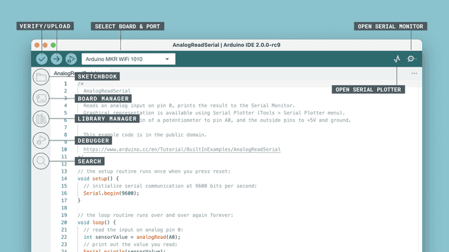
The main screen is organised differently, to show off the new capabilities and to make development faster and easier. The new “Remote Sketchbook” has been integrated closely with the Arduino Cloud, to allow for easy switching between computers during development. V2.0 will pick up any Cloud sketches automatically, while computers using the previous versions of the IDE can still access the sketches via the Web Editor as before.

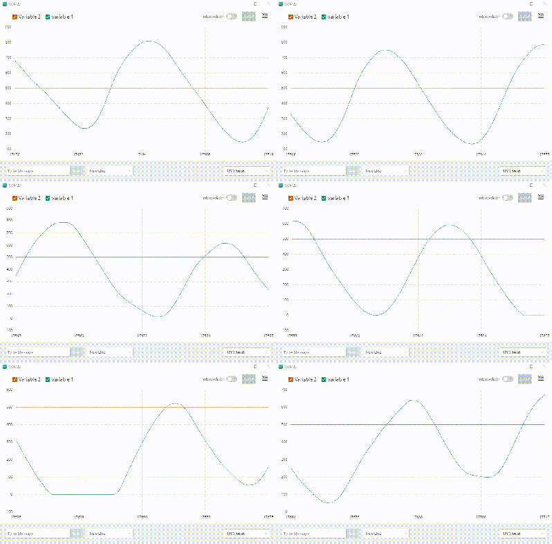
The Serial Plotter can now be used at the same time as the text Serial Monitor, rather than having to choose one or the other. In addition, there is a host of new Debug functionality for those devices that support it. This works with the usual In-Circuit Emulators (such as the Atmel ICE), but also natively with newer Arduino boards like the Arduino Zero without any additional hardware. The debugger gives you access to powerful features like Breakpoints, Step-Into and Step-Over to really understand what your code is doing.

Installation is straightforward, and will automatically pull in any libraries and sketches that you created in previous versions of the Arduino software to ease the transition.

There’s a lot to like in the new IDE, but we expect it will take a little while to discover and use all the new features effectively.  Some of them are carry-overs from the “Arduino Pro IDE” that we covered a few years ago, but it’s great to see the software evolve and improve over time.

Have you tried new new IDE yet?  What are your thoughts on how it compares to the older version, or other development environments?  Let us know in the comments.

Thanks to [cardboardBaron] for the tip.

Open-Source ARM Development Simplified

The ARM series of processors are an industry standard of sorts for a vast array of applications. Virtually anything requiring good power or heat management, or any embedded system which needs more computing power than an 8-bit microcontroller is a place where an ARM is likely found. While they do appear in various personal computers and laptops, [Pieter] felt that their documentation for embedded processors wasn’t quite as straightforward as it could be and created this development board which will hopefully help newbies to ARM learn the environment more easily.

Called the PX-HER0, it’s an ARM development board with an STM32 at its core and a small screen built in. The real work went in to the documentation for this board, though. Since it’s supposed to be a way to become more proficient in the platform, [Pieter] has gone through great links to make sure that all the hardware, software, and documentation are easily accessible. It also comes with the Command Line Interpreter (CLI) App which allows a user to operate the device in a Unix-like environment. The Arduino IDE is also available for use with some PX-HER0-specific examples.

[Pieter] has been around before, too. The CLI is based on work he did previously which gave an Arduino a Unix-like shell as well. Moving that to the STM32 is a useful tool to have for this board, and as a bonus everything is open source and available on his site including the hardware schematics and code.

Simple Clock from Tiny Chip

If you haven’t jumped on the ESP8266 bandwagon yet, it might be a good time to get started. If you can program an Arduino you have pretty much all of the skills you’ll need to get an ESP8266 up and running. And, if you need a good idea for a project to build with one of these WiFi miracle chips, look no further than [Ben Buxton]’s dated, but awesome, NTP clock.

While the ESP8266 started out as an inexpensive, reliable way to get WiFi capability on essentially anything (and paving the way for a plethora of Internet of Things projects), it was quickly hacked to become a fully programmable development board that can stand on its own. To that end, [Ben] has recognized its capability to run a very minimalistic NTP clock. The standard C++/Arduino environment is available, so he didn’t have to learn any new skills. The parts list is stripped down as well: besides the ESP8266, there’s little more than the four-part seven-segment display. There’s even an Arudino library for these chips that [Ben] made great use of. From there, it’s just a matter of wiring it all up and syncing it with an NTP server.

While it’s not the most involved hack ever, it’s good to be reminded that these chips are cheap and readily available for literally anything that you could imagine. If you haven’t started yet, there’s no reason not to. You can use them to control something like an irrigation system, or if you’re even more adventurous, they can run a 3D printer, too.

Thanks [Itay] for the tip!


Filed under: clock hacks
Hack a Day 11 Sep 15:00

Arduino vs. Phidgets vs. Gadgeteer

A few days ago, we saw a dev time trial between the Arduino and Phidgets, a somewhat proprietary dev board that is many times more expensive than an Arduino. The time trial was a simple experiment to see which platform was faster to prototype simple circuits. As always in Hackaday comments, there was a ton of comments questioning the validity and bias of the test. Not wanting to let a good controversy go to waste, [Ian Lee] tossed his hat into the ring with the same dev trial with the Gadgeteer.

The Gadgeteer has the same design philosophy as Phidgets: modular components and a unique software system -the Gadgeteer is based on .NET Micro Framework – that allows you to get up and running quickly. Unlike Phidgets, the Gadgeteer is priced competitively with the Arduino, and the mainboard is priced within an order of magnitude of a single ATMega chip.

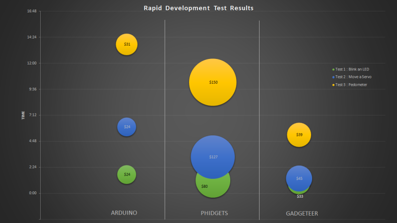
[Ian] pulled off three project with the three development platforms: blinking a LED, moving a servo, and building a pedometer with an accelerometer. For each trial, the time taken and the price of all components were added up. Here’s the relevant graph:

According to the tests, the Gadgeteer won by a large margin. We’re not going to call this a definitive test, and no sane person should think it is. It does, however, highlight the benefits of a well-designed ‘module-based’ development system combined with a good IDE: the Gadgeteer is consistently faster than Phidgets, and just a bit more expensive than an Arduino.

While a time trial consisting of one developer writing code to blink a LED, move a servo, and read a pedometer is hardly enough to make any conclusions, it does demonstrate that the Gadgeteer isn’t that much more expensive than using an Arduino. We’ll leave the rest of the discussion to the commentors below.


Filed under: reviews, Software Development

Arduino vs. Phidgets – Dev Time Trials

Is developing on an Arduino too slow? Are Phidgets too expensive? When might you use one or the other? Hackaday regular [Ken] breaks down what he learned from three experimental time trials.

The main development differences between Arduino and Phidgets are a mix of flavor preferences and some hard facts. The Arduino is open source, Phidgets are proprietary. Arduino requires a mix of hard- and software where Phidgets only needs (and only allows) a connection to a full computer but enables high level languages – it is expected to get the job done sooner and easier. And finally, Arduinos are cheap, Phidgets are 3-5x the cost.

The three time trials were common tasks: 1. Blink an LED. 2. Use a pot to turn a servo. 3. Build a pedometer. For [Ken], the Phidgets won in each of the three experiments, but not significantly: 37%, 45%, and 25% respectively. The difference is only minutes. Even considering time value, for most hackers it is not worth the cost.

In context, the advantages of a mildly more rapid development on the simplest projects are wasted away by needing to rebuild a permanent solution. Chained to a PC, Phidgets are only useful for temporary or fixed projects. For many of our readers that puts them dead in the water. Arduinos may technically be dev kits but are cheap enough to be disposed of in the project as the permanent solution – probably the norm for most of us.

[Ken] points out that for the software crowd that abhor electronics, Phidgets plays to their preferences. Phidgets clips together their pricey peripherals and the rest is all done in code using familiar modern languages and libraries. We wonder just how large this group could still be; Phidgets might have been an interesting kit years ago when the gulf between disciplines was broader but the trend these days is towards everyone knowing a little about everything. Hackaday readers probably represent that trend more than most, but let us know if that seems off.

[Ken]’s article has much more and much better detailed explanations of the experiments and the tradeoffs between the platforms.

If you enjoy watching parallel engineering, see the time-lapse video below for a split screen of the time trials.


Filed under: reviews, Software Development

Intel launches Galileo, an Arduino-compatible development board

Notice how so many maker projects require open-source hardware like Arduino and Raspberry Pi to function? Intel has, and the company is leaping into bed with the former to produce the Galileo development board. Galileo is the first product packing Intel's Quark X1000 system-on-chip, Santa Clara's (designed in Ireland, trivia fans) new low-power gear for wearables and "internet of things" devices. Don't imagine, however, that Intel is abandoning its X86 roots, as Quark's beating heart is a single-thread Pentium-based 400MHz CPU. As part of the new project, Intel will be handing out 50,000 of the boards to 1,000 universities over the next 18 months -- a move which we're sure will make Eben Upton and Co. delighted and nervous at the same time.

Filed under: Misc, Wireless, Intel

Comments

Engadget 03 Oct 12:18

Review: Gooligum Electronics PIC Training Course and Development Board

Introduction

[Updated 18/06/2013]

There are many types of microcontrollers on the market, and it would be fair to say one of the two most popular types is the Microchip PIC series. The PICs are great as there is a huge range of microcontrollers available across a broad range of prices. However learning how to get started with the PIC platform isn’t exactly simple. Not that we expect it to be, however a soft start is always better. There are some older books, however they can cost more than $100 – and are generally outdated. So where do you start?

It is with this problem in mind that led fellow Australian David Meiklejohn to develop and offer his PIC Training Course and Development Board to the marketplace via his company Gooligum Electronics.

In his words:

There is plenty of material available on PICs, which can make it daunting to get started.  And some of the available material is dated, originally developed before modern “flash” PICs were available, or based on older devices that are no longer the best choice for new designs.  Our approach is to introduce PIC programming and design in easy stages, based on a solid grounding in theory, creating a set of building blocks and techniques and giving you the confidence to draw on as we move up to more complex designs.

So in this article we’ll examine David’s course package. First of all, let’s look at the development board and inclusions. Almost everything you will need to complete all the lessons is included in the package, including the following PIC microcontrollers:

You can choose to purchase the board in kit form or pre-assembled. If you enjoy soldering, save the money and get the kit – it’s simple to assemble and a nice way to spend a few hours with a soldering iron.

Although the board includes all the electronic components and PICs – you will need are a computer capable of running Microchip MPLAB software, a Microchip PICkit3 (or -2) programming device and an IC extractor. If you’re building the kit, a typical soldering iron and so on will be required. Being the  ultra-paranoid type, I bought a couple extra of each PIC to have as spares, however none were damaged in my experimenting. Just use common-sense when handling the PICs and you will be fine.

Assembly

Putting the kit board together wasn’t difficult at all. There isn’t any surface-mount parts to worry about, and the PCB is silk-screened very well:

The rest of the parts are shipped in antistatic bags, appropriately labelled and protected:

Assembly was straight forward, just start with the low-profile parts and work your way up. The assembly guide is useful to help with component placement. After working at a normal pace, it was ready in just over an hour:

The Hardware

Once assembled (or you’ve opened the packaging) the various sections of the board are obvious and clearly labelled – as they should be for an educational board. You will notice a large amount of jumper headers – they are required to bridge in and out various LEDs, select various input methods and so on. A large amount of jumper shunts is included with the board.

It might appear a little disconcerting at first, but all is revealed and explained as you progress through the lessons. The board has decent rubber feet, and is powered either by the PICkit3 programmer, or a regulated DC power source between 5 and 6V DC, such as from a plug-pack if you want to operate your board away from a PC.

However there is a wide range of functions, input and output devices on the board – and an adjustable oscillator, as shown in the following diagram:

The Lessons

There is some assumed knowledge, which is a reasonable understanding of basic electronics, some computer and mathematical savvy and the C programming language.

You can view the first group of lessons for free on the kit website, and these are included along with the additional lessons in the included CDROM. They’re in .pdf format and easy to read. The CDROM also includes all the code so you don’t have to transcribe it from the lessons. Students start with an absolute introduction to the system, and first learn how to program in assembly language in the first group of tutorials, followed by C in the second set.

This is great as you learn about the microcontroller itself, and basically start from the bottom. Although it’s no secret I enjoy using the Arduino system – it really does hide a lot of the actual hardware knowledge away from the end user which won’t be learned. With David’s system – you will learn.

If you scroll down to the bottom of this page, you can review the tutorial summaries. Finally here’s a quick demonstration of the 7-segment displays in action:

Update – 18/06/2013

David has continued publishing more tutorials for his customers every few months – including such topics as the EEPROM and pulse-width modulation. As part of the expanded lessons you can also get a pack which allows experimenting with electric motors that includes a small DC motor, the TI SN75441 h-bridge IC, N-channel and P-channel MOSFETS and more:

So after the initial purchase, you won’t be left on your own. Kudos to David for continuing to support and develop more material for his customers.

Where to from here? 

Once you run through all the tutorials, and feel confident with your knowledge, the world of Microchip PIC will be open to you. Plus you now have a great development board for prototyping with 6 to 14-pin PIC microcontrollers. Don’t forget all the pins are brought out to the row of sockets next to the solderless breadboard, so general prototyping is a breeze.

Conclusion

For those who have mastered basic electronics, and have some C or C-like programming experience from using other development environments or PCs – this package is perfect for getting started with the Microchip PIC environment. Plus you’ll learn about assembly language – which is a good thing. I genuinely recommend this to anyone who wants to learn about PIC and/or move into more advanced microcontroller work. And as the entire package is cheaper than some books –  you can’t go wrong. The training course is available directly from the Gooligum website.

Disclaimer – The Baseline and Mid-Range PIC Training Course and Development Board was a promotional consideration from Gooligum Electronics.

In the meanwhile have fun and keep checking into tronixstuff.com. Why not follow things on twitterGoogle+, subscribe  for email updates or RSS using the links on the right-hand column? And join our friendly Google Group – dedicated to the projects and related items on this website. Sign up – it’s free, helpful to each other –  and we can all learn something.

The post Review: Gooligum Electronics PIC Training Course and Development Board appeared first on tronixstuff.
Robotic Development Platform

Hello everybody :)

I made this blog to tell you all about my latest project, after my Robotic Arm project has died out a little.

This little thing will be my first actual "robot". The whole idea behind it is that I will have a platform which will be easy to further develop, and thus be awesome to learn new stuff. 

read more

Let's Make Robots 06 Aug 23:27