Posts with «nixie clock» label

Upcycled Nixie Clock Fit For A Friend

Building a clock from parts is a right of passage for makers, and often represents a sensible introduction into the world of electronics. It’s also hard to beat the warm glow of Nixie tubes in a desktop clock, as [Joshua Coleman] discovered when building a Nixie tube clock for a friend.

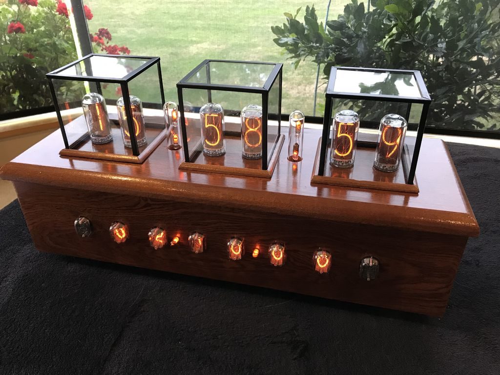
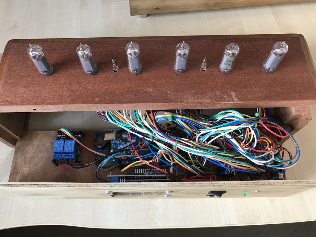
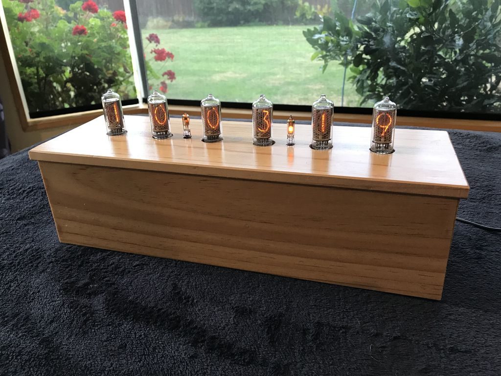
The original decision to upcycle the chassis from an unrepairable Heathkit function generator came a little undone after some misaligned cutting, so the front panel ended up being redesigned and 3D printed. This ended up being serendipitous, as the redesigned front panel allowed the Nixie tubes to be inset within the metal chassis. This effect looks great, and it also better protects the tubes from impact damage.

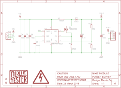
Sourcing clones of the 74141 Nixie driver ICs ended up being easier than anticipated, and the rest of the electronics came together quickly. The decoders are driven by an Arduino, and the IN-4 Nixie tubes are powered by a bespoke 170 volt DC power supply.

Unfortunately four of the tubes were damaged during installation, however replacements were readily available online. The gorgeous IN-4 Nixie tube has a reputation for breaking easily, but is priced accordingly on auction sites and relatively easy to source.

The build video after the break should get any aspiring Nixie clock makers started, but the video description is also full of extra information and links for those needing help getting started.

We’re not short on clock hacks here at Hackaday, so why not check out a couple more? This retro-inspired LED clock looks like its right out of a parallel universe, or maybe this stunning Nixie clock driven by relays will strike your fancy.

Hack a Day 08 Apr 00:00

Geometric Nixie tube clock and environmental display

Creators keep coming up with new clock designs, and while you might think that every new possibility has been exhausted, Christine Thompson has proved this assumption wrong once again with her “VFD Trilateral Clock.

This Arduino Uno-powered device employs a stepper motor to rotate a triangular prism shape with scales for hours and minutes on one side, temperature in Celsius and Fahrenheit on the other, and humidity and pressure on the third surface.

The geometric scale travels in 120-degree steps, causing each face to line up with a pair of IN-13 Nixie tubes on either side. These linear tubes are then used to indicate time and environmental conditions in a beautiful bell jar display, as seen at around 3:30 in the video below.

While waiting for the delivery of parts for another project I decided to push ahead with this project. At its heart is two IN-13M Nixie tubes. These tubes are designed to provide a linear scale between maximum and minimum points using an illuminated column. The project uses two of these IN-13M, three wire Nixie tubes to show, time (Hours and Minutes), temperature (Celsius and Fahrenheit), Humidity (percentage), and Pressure (millibars).

At this point I would like to thank Dr. Scott M. Baker for his great web site, which provided me with all the information I needed to get these Nixie tubes to work. In particular the Current Regulator as displayed and detailed on his web site.

The project uses a BME280 sensor to determine the temperature, pressure and humidity and RTC clock to monitor time. As the system needs to display six different values it was necessary to construct a rotating central display which showed these values against six scales. In order to achieve this an equilateral triangle of wood was fashioned, each side showing two sets of values. A stepper motor was mounted under the top platform and this motor rotates through 120 degrees in time for the next set of values to be displayed on the two Nixie tubes.

Arduino Shield Makes Driving Nixies Easy

Nixie tubes are adored by hackers across the world for their warm glow that recalls an age of bitter nuclear standoffs and endless proxy wars. However, they’re not the easiest thing to drive, requiring high voltages that can scare microcontrollers senseless. Thankfully, it’s possible to score an Arduino shield that does the heavy lifting for you.

The HV supply is the heart of any Nixie driver.

The shield uses HV5812 drivers to handle the high-voltage side of things, a part more typically used to drive vacuum fluorescent displays. There’s also a DHT22 for temperature and humidity measurements, and a DS3231 real time clock. It’s designed to work with IN-12 and IN-15 tubes, with the part selection depending on whether you’re going for a clock build or a combined thermometer/hygrometer. There’s also an enclosure option available, consisting of two-tone laser etched parts that snap together to give a rather sleek finished look.

For those looking to spin up their own, code is available on Github and schematics are also available. You’ll have to create your own PCB of course, but there are guides that can help you along that path. If you’re looking to whip up a quick Nixie project to get your feet wet, this might just be what you need to get started. Of course, you can always go straight to hard mode, and attempt a functional Nixie watch. Video after the break.

Slot

Gorgeous Nixie clock features three types of tubes

Nixie tubes require electricity in the range of 180VDC, making them challenging to work with. Maker Christine Thompson, however, decided to take Nixie art to a new level, creating a clock with three different types of tubes! 

This clock, or perhaps more accurately “info display,” shows the time and date with six IN-18 tubes mounted on the top. In the front, six IN-12A and two IN-15A tubes are also available to show time, date, pressure, temperature, and humidity.

A pair of Arduino Mega boards are used to control this retro-inspired contraption, along with an array of wiring, perf board, and other components, stuffed inside a very nice wooden enclosure. 

This is my first Nixie styled clock I have constructed. The clock actually consists of two clocks, the first being a 6 x IN-18 tube clock which is mounted on the clock’s top and displays both time and date. The second clock, this time based on 6 x IN-12A and 2 x IN-15A nixie tubes displays at the front of the clock and can display, time, date, pressure (with units and trend), temperature (both Centigrade and Fahrenheit) and, humidity (with units and trend). The time and date are separated with two single neon lamp-based separators, while only one of these lamps is displayed, to represent a decimal point, when the pressure, humidity or temperature is displayed. Both these clocks use “Direct/Static Drive” to power the displays and are based on two Arduino Mega 2560 boards. The fourteen tubes are driven by 12V to 170V DC to DC boost power supplies and 14 x K155 IC chips. The clock also powers two sets of Neon Lamps which switch off while the clock goes through its cathode cleaning cycle which happens at 19, 39 and 55 minutes past each hour. This cathode cleaning cycle consists of all six tubes displaying the digits 0 through 9 in sequence 6 times.

In addition the clock will sound a chime at 15, 30, 45 and 60 minutes. At the 60 minute chime the hour chime is also sounded. The chimes are standard MP3 files using a simple MP3 player controlled by the Arduino mega. In order to save on tube life all tubes are switched off automatically when the light level in the room dims to a predefined level, this is achieved using a LRD resistor located at the back of the clock. To help dissipate any heat build up both Arduino Mega ICs have copper heat fins attached and a 5V fan draws air out of the clock, cool air entering through a hole in the bottom plate.

The user can adjust the time, date, chimes, and chimes volume using one of two 16×2 LCD displays, located at the back of the clock. The BME280 temperature, humidity, and pressure sensor is mounted on the back of the clock so as to not be affected by the clock’s internal temperature.

A demo is seen in the video below, while more info and Arduino code can be found in the project’s write-up.