Posts with «nixie» label

My impression of Akafugu Nixie Modular Clock

You are reading the first ever "review" of the Akafugu Nixie Modular Clock, a product yet to be released at the time of writing. Per, of Akafugu, generously offered to sell me the PCBs for this Nixie clock; the parts were sourced by myself.


The Nixie Modular Clock shares a big chunk of the schematic with its older sibling, the Akafugu Nixie Clock. The goal of this latest design is, I assume from the name, the "modularity". Similar to the VFD Modular Clock, "shields" for various types and numbers of Nixie tubes will probably be developed soon.

The hardware
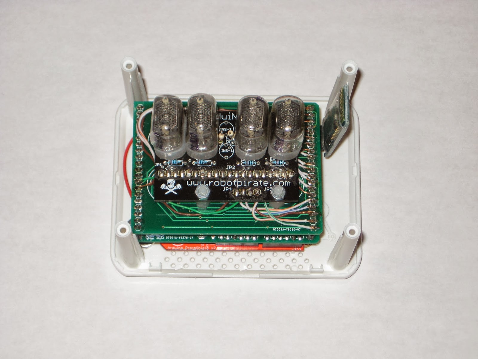
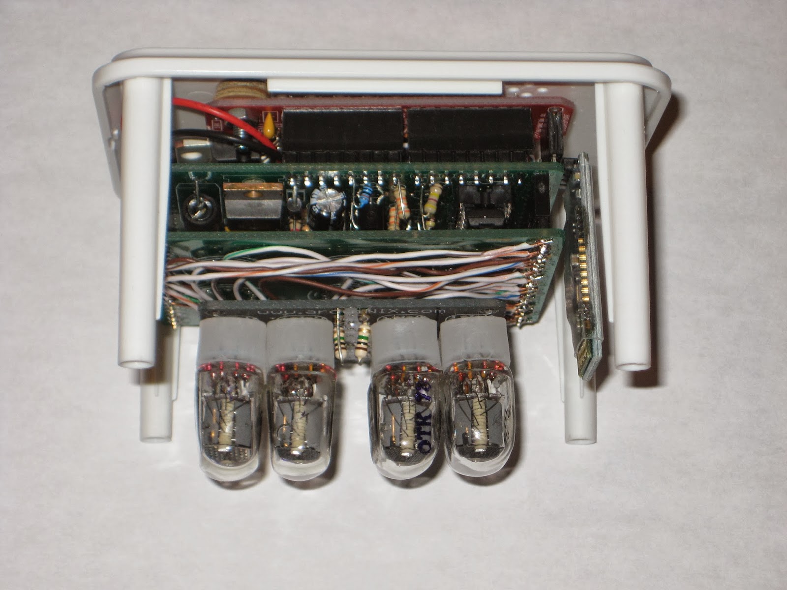
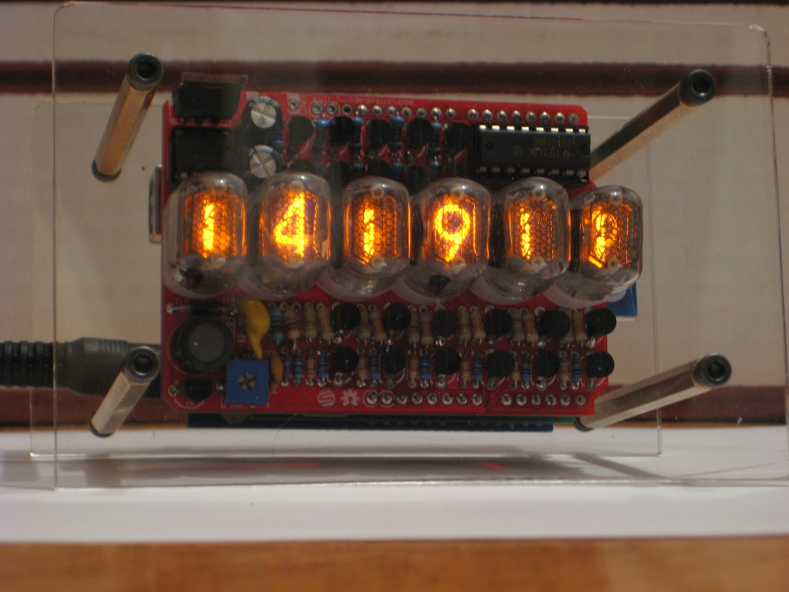
This Nixie Modular Clock is an Arduino-based, open source project, designed around ATmega328 running on internal oscillator at 8MHz. Like the Akafugu Nixie mk3, the high voltage source (180-200V) uses the MC34063 DC-DC converter, and the driver for Nixies is HV5812. There are 3 buttons: 2 in the back, for setting up the time and alarm time, and another long-stem, protruding through the top board, for enabling/disabling the alarm. An orange LED in the front indicates if the alarm is active or not.
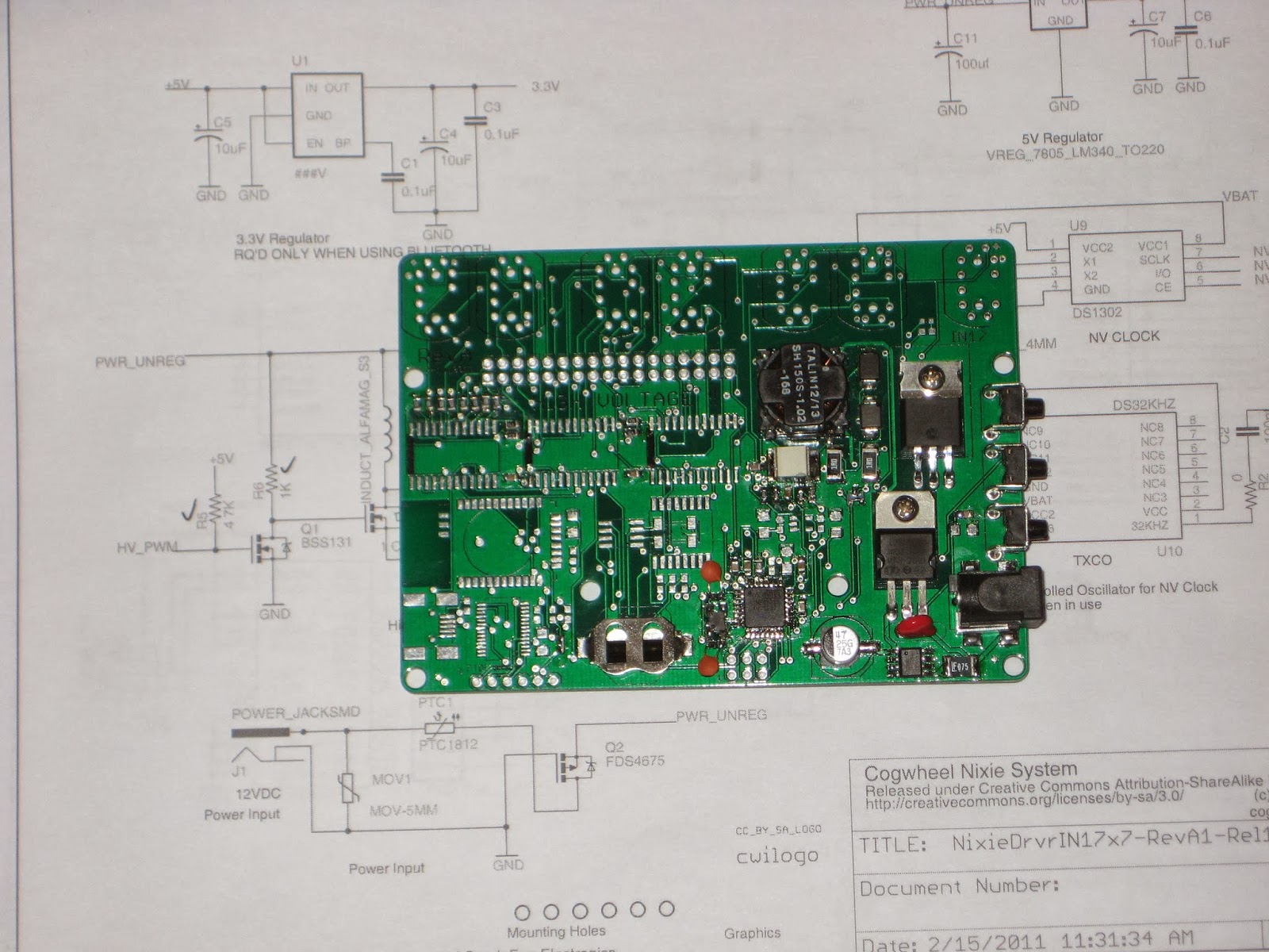
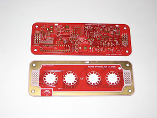
The PCB for the commercial version will be red, I was told (as shown below :).


Assembly
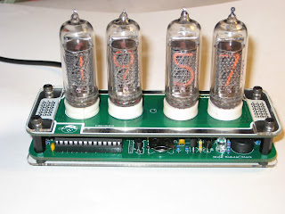
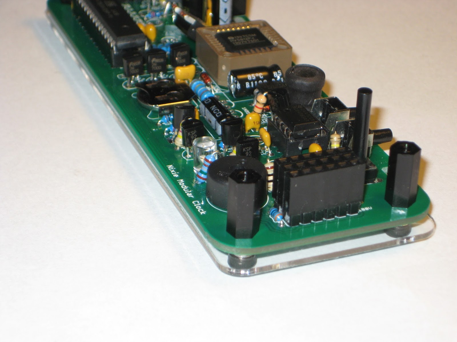
Building the clock is straightforward (as long as all parts are in hand, which will be the case when the kit becomes available). The assembly instructions are easy to follow and very clear, with lots of details and helpful photos. Some of the parts I picked (electrolytic capacitors, inductor) were a little too high, so I had an issue with the clearance between the 2 boards. I was able to "correct" that (meaning increase the distance between boards) by using long-legged headers lifted on male-headers plastic insulators (see the photo below).


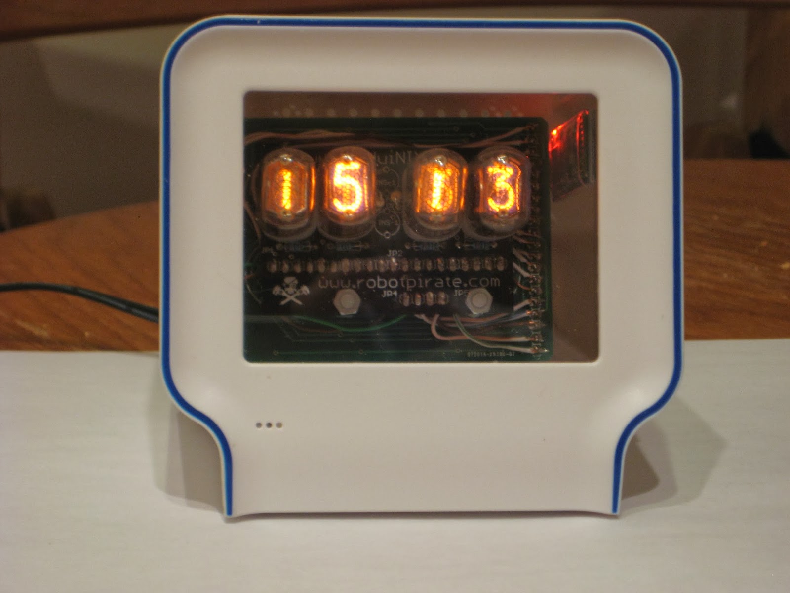
I did not install the lamp between the hours and minutes. I was surprised to see that the unit-hours tube (second from left) blinks its decimal point!
The clock has also support for "background" LEDs (blue recommended), but I did not solder those either.

The software..
..is also open source and available here. A nice feature that every programmer will love is that it covers both Nixie Clock and Nixie Modular Clock (plus variants of the latter, like 6-tube clock) by using macro definitions. Not to mention that the code compiles and works without a glitch. It also has support for GPS.

Enclosure
Although I like the elaborate enclosure that Akafugu designed, I tried my own, by using simple plates to cover the exposed soldered pins, on both top and bottom. To me, the open sides are ok as long as small children don't stick their fingers (or grownups screwdrivers) in there :)
My suggestion is to make the top plastic plate of the enclosure (shown in akafugu's photo of the clock) transparent, rather than opaque black, which hides the elaborate design/silkscreen of the tube PCB.

Conclusion
I think that the Modular Nixie Clock will be another success. Its aesthetics, compact size and feature-rich software set a new standard in the world of Nixie clocks. Remember, most of the Nixie clocks one can buy on etsy, ebay or other sites, are non hack-able hardware or software. If you want one to tinker with, then Akafugu Modular Clock is for you.

Wise time with Arduino 07 Jul 02:01
nixie  review  

Adorable, Interactive Nixie Tube “Pet” Performs Simple Math

  Nixie tubes (or cold cathode displays) are awesome and although the technology isn’t new (they hit the market back in 1955) they are making a strong comeback in the 21st century thanks to the maker community. Ron Soyland has been making vacuum tubes for years and his love for […]

Read more on MAKE

World’s Largest “Nixie” Clock at World Maker Faire

World Maker Faire was host to some incredible projects. Among the favorites was Nixie Rex [YouTube Link]. Nixie Rex is actually a Panaplex display, since it’s glow comes from 7 planer segments rather than 10 stacked wire digits. One thing that can’t be contested is the fact that Rex is BIG. Each digit is nearly 18 inches tall!

Nixie Rex was created by [Wayne Strattman]. Through his company Strattman Design, [Wayne] supplies lighting effects such as plasma globes and lightning tubes to the museums and corporations. Nixie Rex’s high voltage drive electronics were created by [Walker Chan], a PHD student at MIT. Believe it tor not the entire clock runs on an ATmega328P based Arduino. The digits are daisy chained from the arduino using common Ethernet cables and RJ45 connectors. A Sparkfun DS1307 based real-time clock module ensures the Arduino keeps accurate time.

[Wayne] and Rex were located in “The Dark Room” at Maker Faire, home to many LED and low light projects. The dim lighting certainly helped with the aesthetics, but it did make getting good photos of the clock difficult. Long time Hackaday tipster [Parker] graciously provided us with a size reference up above.

Click past the break to see a closeup of that awesome cathode glow, and a video of the Nixie Rex  in action.

Got to love that tube glow.


Filed under: clock hacks

Single digit Nixie tube micro clock

This single-digit Nixie clock is built on a piece of prototype board, as a ProMini shield, similar to two previous miniature clocks, the single-digit numitron clock and the 7-segment bubble clock. The shield holds the Nixie board and the high-voltage power source (both from Taylor Electronics). It also has a couple of buttons to set up the time and 4 LEDs to indicate the digit's position.


Like the single-digit numitron clock, time is displayed by showing each of the 4 digits (as in HH:MM). But for a "clearer picture", I added the above-mentioned 4 different color LEDs.
One of its nice features is that it works on the rechargeable 3.7V LiPo battery.

The clock does not have an on-board RTC (lack of space), relying instead on the time-measuring capabilities of ATmega328 directly. So this clock will keep time for as long as the battery is kept charged (through the USB power cable).

The photo below shows my "collection" of (un-synchronized) micro clocks. (Missing is the numitron clock, which requires a stand; I am still waiting for a part to build that).


The right-most one follows the same ProMini shield idea, using an I2C OLED display and running the Pong sketch (courtesy of miker).

Wise time with Arduino 27 May 19:05
nixie  

Single digit numitron tube tiny clock

There is no "dumb" display easier to connect to an Arduino (or any microcontroller, for that matter) than a numitron tube, even compared with the 7-segment LED display. This is because:
  • unlike LEDs, it does not need current-regulating resistors;
  • unlike LEDs, the segments are not polarized; just connect any end of a segment to Vcc and the other to ground and it lights up; basically, every segment is the filament of a light bulb, like those used in flashlights in the old days; like light bulbs, they even get warm after a while (hence their inefficiency);
  • voltage range is pretty wide, between 2V and 5V;


The most popular numitron tube is IV-9, which can be purchased these days on ebay for $5.
Size-wise, IV-9 fits perfectly on a Arduino ProMini board, and so it can be soldered directly into the bottom holes of that board. The clock I made displays the HHMM-formatted time as a sequence of 4 digits. Since there is no RTC on board, the processor keeps track of passing time. The rechargeable LiPo battery plays the role of the backup power, in case the USB cable is unplugged. The current consumption is about 20mA per segment, making the clock draw between 50mA and 160mA. With the on board 240mAh LiPo battery, the power would last for a maximum of 2 hours. The display can be turned off (left button) to save power, thus making it suitable as a wearable device (watch). In this case, the clock draws only about 10mA.
The right button is used for setting up the time.


The numitron clock doesn't get any smaller than this.


The cost of building this tiny numitron clock is about $12:
- Arduino ProMini, with ATmega328 (about $3 on ebay);
- IV-9 numitron tube ($5 on ebay)
- LiPo charger module ($2 on ebay)
- 240mAh LiPo battery ($2 on ebay)
- 2 tactile push buttons ($0.5 on ebay)

The only problem I had was with the ProMini bought on ebay. Sometimes they come with no bootloader burned on the microcontroller. Once anything is soldered on the board (e.g. headers), burning the bootloader through the ICSP becomes almost impossible (because of space constraints).
Therefore, before including it in a project, always test the bare ProMini by uploading a sketch.


Wise time with Arduino 08 May 15:20
nixie  

Chumby Nixie clock

With my limited (read "non-existent") crafting resources (e.g. space, tools), the easiest way to enclose my Arduinix clock was by recycling my late Chumby's shell. Things almost magically fit together, with minimal thinking and work. I was able to cram inside the box a hand-wired Wiseduino with an Arduinix-remix shield and a 4-tube board.


The old Wiseduino would have come in handy if I had any left. I made one using the protoshield from Sparkfun, which also has a connector for the Bluetooth JY-MCU module. Beside the ATmega328, this pseudo-Wiseduino board includes a DS1307 with coin backup battery and a 7805 voltage regulator.

The tube board is attached with screws to an empty board that plugs in the Arduinix-remixed shield. (Note that one reason for "remixing" Arduinix was to re-arrange the parts sticking out, namely the mosfet and the capacitors, so that it allows another shield to be stacked on top.)


The clock has no user button (I glued the original snooze button on top, would have required extra work to re-use it), so the time is set through the bluetooth interface, similarly to my other Arduino Nixie clock.


The sketch (compiled with Arduino 1.0.4) is available here. Note that, unlike the original Arduinix sample sketch, the nixie-driving code is now using interrupts. This decouples the display logic from the clock functionality, also allowing for the addition of a buzzer alarm.

Wise time with Arduino 13 Jan 16:34
bluetooth  nixie  

My first impression on Cogwheel Nixie clock

Many months ago I bought, attracted by the clearance price, the PCB for the "Nixie Driver Board Rev A" from "Cogwheel circuit works" store. I was hoping that, with all documentation in place, I would be able to build it on my own, considering it's controlled by an ATmega328 and the software was available, though not the source code.

First thing to note is that the board uses mostly SMDs. If anything went wrong (and there was a high chance, since the PCB was already described as a "mistake the board house made"), the board would become a coaster.

The schematic includes some exotic components, like the HV513 Nixie driver, not offered by digikey. Others are the DS1302 RTC and the optional DS32KHZ oscillator for RTC, which I heard of for the first time. But thanks to the detailed BOM, gathering the components was relatively (some of them are already discontinued, for example) easy.

High voltage for the Nixie tubes is generated by a hardware PWM under software control. So, like the Ice Tube Clock, in order to measure the high voltage and make sure the HV circuitry works, some software must be uploaded onto the processor. I expected the released software to do that. Unfortunately, the highest voltage I saw was under 9V.


After some digging (and learning in the process), I ended up with this simple sketch, adapted from Satashnik Nixie clock, which generates a stable 190V. I know, I was surprised too :)

#include "Arduino.h"

#define DDRHVPUMP  DDRB
#define BV2(a,b) (_BV(a)|_BV(b))
#define BV6(a,b,c,d,e,f) (_BV(a)|_BV(b)|_BV(c)|_BV(d)|_BV(e)|_BV(f))
#define VOLTAGE_WASTE   370                     //!< ~180V
#define VOLTAGE_SAVE    355                     //!< ~170V

volatile uint16_t voltage; 
static volatile uint16_t voltage_setpoint = VOLTAGE_WASTE;
static const uint16_t ocr1a_reload = 60;

void pump_init()
{
    // set fast pwm mode
    // COM1A1:0 = 10, clear oc1a on compare match, set at top
    // COM1B1:0 = 00, normal port operation
    // no FOC
    // WGM11:10 (WGM = Fast PWM, TOP=ICR1: 1110) = 11
    TCCR1A = BV2(COM1A1, WGM11);
    TCCR1B = BV2(WGM13,  WGM12);
    OCR1A = ocr1a_reload; 
    ICR1 = 170;
    TCCR1B |= _BV(CS10); // clk/1 (16MHz)
    DDRHVPUMP |= BV2(1,2);
}

void adc_init()
{
    voltage = 0;
    // PORTA.6 is the feedback input, AREF = AREF pin
    ADMUX = 6;  
    // ADC enable, autotrigger, interrupt enable, prescaler = 111 (divide by 32)
    ADCSRA = BV6(ADEN, ADATE, ADIE, ADPS2, ADPS1, ADPS0); 
    ADCSRA |= _BV(ADSC); 
}

/// Start voltage booster
void voltage_start()
{
    adc_init();
    pump_init();
}

ISR(ADC_vect)
{
    voltage = (voltage + ADC) / 2;
    if (voltage < voltage_setpoint) {
        OCR1A = ocr1a_reload;
    } else {
        OCR1A = 0;
    }
}

void setup()
{
    sei();
    voltage_start();        // start HV generation    
}

void loop()
{
  // clock functionality in here;
}

The next big step is to write the software to drive the tubes and actually show the time, which is essentially re-writing the Cogwheel Nixie clock code (or at least the basic functionality) from scratch. Then open source it. Any help would be appreciated :)

Nixie tube clock miscellany

Honestly, one of the reasons behind my latest infatuation with Nixie tube clocks is trying to understand why so many people got so fascinated so quickly and so suddenly with them, although they are not cheap, and although they simply show the time with 4, sometimes 6, digits.

In any case, I'm in the bandwagon now. I designed an Arduinix(TM) variant, based on my previous observations. One of the main differences is that the components sit low on the board, so that a "tube shield" can be plugged on top, similar to akafugu's VFD modular clock. The top "tube shield" can host (at least in theory) up to six IN-2 or four IN-17 (four IN-12 would not fit).


For the "IN-2 tube shield", I downloaded and used the eagle library called "russian-nixies.lbr". Guess what? For the digits to be shown vertically, the IN-2 part needs to be rotated about 45 degrees clockwise. I did not know that until I got my IN-2 tubes. Essentially, the IN-2 tube shield I have is kind-of useless now, unless one uses it for an "artist project" (to quote Pete of PV Electronics, seller of Nixie kits on ebay). That means that the tubes are connected to the PCB with wires, so that they can be placed at artist's fancy. I know Nick is an artist :)

Lesson learned: don't design the PCB until you have all parts in hand.

PS Getting the high voltage (180V) on the new board was just a matter of adjusting the trim pot. No surprises this time.

PS2 Although I did not try it yet, the "Open source Nixie tube shield" sketch should work, with minor modifications, with Arduinix, I reckon.

PS3 Please contact me if you have a need for this PCB or want to buy one.

Wise time with Arduino 22 Nov 03:47
general  nixie  

Another Nixie clock

For "unknown" reasons, these days things don't move as fast as they used to. I have a dozen or so unfinished projects on my desk, most of them waiting for parts to arrive. And usually and unfortunately, when I get the long awaited part, something else is missing... or not fitting,... or not working.
Today I was finally able to finish the "Open Source Nixie Tube Shield", for which I pledged $15 on kickstarter in return for the PCB.
Without paying attention to the schematic (was it even published before the campaign ended?), I thought it was just another variation of the same Nixie theme, which it really was. I expected to have all parts on hand already, including the Nixie K155ID1 driver Russian IC. Surprise! Instead, the circuit uses CD4028 decoder plus HV transistors. And that's where the 4 week wait is coming from.

I liked the compactness of the board even before I soldered the almost 100 components. But I was a bit disappointed when I realized the shield had a (minor) flaw: the area above Arduino's USB A connector is as highly populated as the rest, if not more. Not only the metal encasing of the USB connector will short the high voltage components on the shield above, but the shield cannot be even pushed all the way in.
A workaround (which I ended up using) is to have an intermediary shield between Arduino and the Nixie tube shield. Another solution is to use an Arduino variant with the mini B USB, like Seeeduino or Leonardo.

But all's well that ends well. To cut the story short, the sample sketch provided worked just fine without interventions. Hardware-wise, I added a DS1307 RTC (since I was going to build a clock), a buzzer (for alarm and chime) and a Bluetooth module (to set up the time without buttons). The only kludge required was a change in the core file Tone.cpp, where I replaced Timer2 with Timer1.

Below are a few photos. For enclosure, I (again) went for the the poor-man's solution, this time hand-cut (as opposed to laser-cut) transparent acrylic plates. (The long standoffs are 60mm, in case one wants to reproduce the experiment.)


I was happy to "upcycle" my Arduino Duemilanove, with the nice bottom exposed and visible :)
The prototype shield was something that I thought I will never use again, but it came in handy.


I also borrowed an idea from akafugu, with the bigger front plate creating a nice slope.


One thing I skipped (because I don't like the combination) is the blue (or any other color, for that matter) LEDs under the tubes.

A working version of the code is available here. It is based on Tyler's code (timer-based multiplexing of the digits, anti-cathode poisoning etc), with added support for RTC (DS1307) and functionality for setting up the time, alarm time, enabling/disabling alarm etc through Bluetooth (using an Android phone or tablet, for example).
The clock can execute the following commands, sent from BlueTerm (after pairing with the device):

  • TIME=hh:mm - sets the current time (second is set to 0);
  • ALARM TIME=hh:mm - sets the alarm time; the alarm hour and minute are also saved to eeprom (and retrieved from there whenever the clock is powered back on);
  • SHOW ALARM - sends back to BlueTerm the alarm hour and minute
  • ALARM ON - enables the alarm; this is also saved to eeprom; the Alarm On/Off status can be shown with a LED connected to A0;
  • ALARM OFF - disables the alarm;
  • STOP ALARM - turn off the sound after the alarm starts beeping;

Note that all commands must be upper case.

The "Stop alarm" feature is reminiscent of Rami's "Deep Sleep iPhone app" and also of Ramos alarm clock (coincidentally, another Nixie clock, close source though), where both of them are asking for user interaction to stop the sounding alarm. Well, in order to stop this Nixie clock from beeping, one needs to open BlueTerm, pair the devices, then type in "STOP ALARM", a sequence of actions that requires anyone to be pretty much awake.

Wise time with Arduino 19 Nov 04:50
bluetooth  nixie  review  

My experience with the Arduinix Nixie tube shield

This was not an easy project to finish. Anything that could go wrong, it did, due to a rare combination of ambiguous hardware kit design (that's what started it all), and bad luck (software bugs in Arduino IDE 1.0 nevertheless). In the end, I learned a few things, which made me a better person :) :) :)

Please don't take this as a rant, nor as a (negative) review. As usual, the main purpose of the post is to document the experience and eventually help others troubleshoot similar problems they may have with the Arduinix shield kit.

The first issue I had was not getting the high voltage (180V) required by the Nixie tubes. For some reason, the provided schematic and assembly instructions are ambiguous on the exact value of the C3. This made me look at other HV power supplies, with the conclusions captured in this post. Anyone taking a closer look at the Arduinix HV schematic will notice at least 3 differences compared to others using the same 555-based design:

- the very important capacitor C3 has unusually small value (only 47pF, compared to 2.2nF, a much better value, according to the calculations);
- pins 6 and 7 are connected;
- transistor Q5 is shown as PNP (though correctly marked as MPSA42, an NPN transistor).


The assembly instructions, showing 2.2nF for C3, say that the value of this capacitor varies "the most", "as we make slight modifications and improvements to the kit". What improvements in a standard, proven and tested schematic?


What else was there for me to try? Most of the components around the oscillator, of course: the inductance, the resistors, the capacitors. The highest voltage I got was about 80V. So I decided to revert to "the standard". I cut (top side) and re-routed (bottom side, see photo) the PCB traces around pin 6, 7 and R14/16, I replaced C3 with a 2.2nF, and, unsurprisingly, I got the long desired 180V.


Next step was the software. After I uploaded the sample sketch using Arduino 1.0, only 2 digits were lit.
Three hours and a lot of effort and frustration later (even wondering how everybody else got this sketch working), I realized that Arduino 1.0 itself was the problem. Even the simplest test sketch, tried on multiple Arduinos, failed, incredibly, to work!!! (And you can try it and confirm this too.) Here it is:

void setup() 
{
  Serial.begin(9600);
  Serial.println("in setup");
}

void loop()     
{
  Serial.println("in loop");
  delay(1000);
}

Switching to Arduino 1.0.4 solved it. My Arduinix shield is now functional. Making it into a clock is going to take a few more steps though, including hardware (adding RTC, probably by resurrecting Wiseduino+), writing the software (with functionality to set up the time from buttons), and of course, the most challenging of them all, making a proper enclosure.


A few more observations:
- the INS-1 neon lamps are too tall to be used as dots between the IN-17 Nixie tubes;
- it seemed that the little Nixie PCB could be placed at the same level as the Arduino board (and under the shield, as opposed to on top, as it is currently, see the photo above); it has holes that align with those in the original Arduino 2009, but the ICSP connector is in the way though;
- all photos on arduinix gallery show the Nixie board attached to the shield by ribbon cables; I wondered a bit if my solution, using regular headers, was proper;
- this is the cheapest open source Nixie-kit out there.


Wise time with Arduino 15 Oct 00:01
nixie  review