High voltage power sources for tubes (Nixie, VFD, Geiger)
This is a superficial review of the few schematics I encountered while building Nixie clocks, VFD clocks and Geiger counters (no tube amplifier just yet). Although the schematics seemed basic at a glance, they usually ended up being a challenge (that is, they rarely worked right away) for me. That's another reason I am trying to cover them here, so I can use this post as consolidated reference any time I need it.
Tubes require high voltage to work. Some (Vacuum Fluorescent Display) need 40V, others (Nixie) 180-200V, and some others (Geiger) even higher, 400-1000V. The high voltages are generated these days by switching-mode power supplies. Essentially, there is only a handful of popular solutions, and each DIY tube kit picks one of these, based on size, power requirements, cost.
In principle, a switching mode power supply, also known as "boost converter", uses a square wave oscillator ("switch") to create magnetic energy in an inductor, then releasing it as high voltage.
Some scientific explanation (with formulas) can be found here, some practical advice (with schematics and photos) here. Adafruit has a very useful online boost calculator.
1. One of the most popular solution for the square wave oscillator is by using the ubiquitous 555. This is inexpensive, but requires some tweaking and adjusting (values of resistors and capacitors). The schematic is standard, but there seem to be a few variations.
The one below is from Ronald Dekker.

Frank clock (from Pete's Nixie kits) uses an almost identical schematic, but a different set of values for R2-R3- C4 (used for setting the frequency). In the end, the oscillator frequency is about the same at approx 30kHz, calculated with formula f = 1/0.693/C4/(R3+2R2) (in the schematic below).

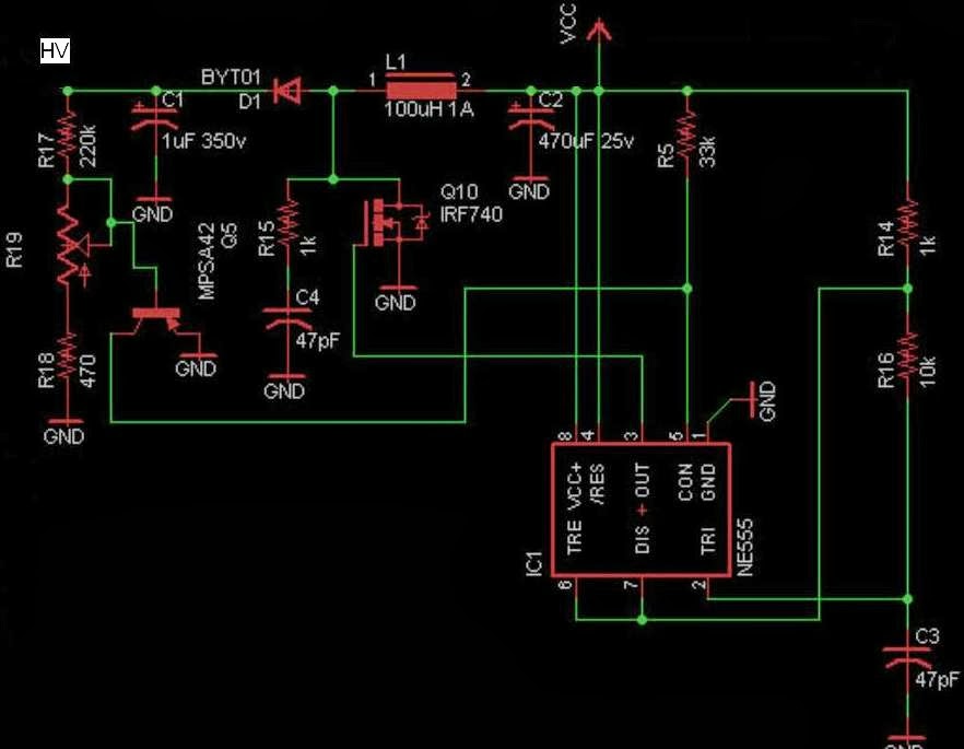
Same 555 is used in Arduinix, but in a different configuration, although still as astable oscillator. This one has an extra HV capacitor (C4) in series with a resistor (R15), whose exact purpose I don't understand. The oscillation frequency is also weird, according to the above formula, with C3 at 47pF, should be 1.5kHz. No wonder this did not work for me.

Another almost identical HV power supply for Nixie tubes is used in the recently-kickstarted "Nixie tube shield" (for which I pledged $15 for the PCB, and yet to receive it).
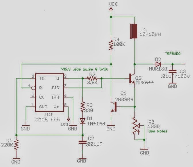
And finally, 555 is also used to generate the higher voltages required by Geiger tubes, as used by BroHogan (and MightyOhm). The frequency of oscillation is 4.5kHz (f = 1/R1/C2). (I built several Geiger kits from BroHogan and they were all trouble-free.)

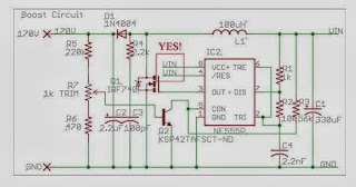
2. Other solutions use specialized chips like MAX1771 and MC34063.
Shown below is the high-efficiency boost converter from Nick de Smith (sold by ogiLumen), based on MAX1771.
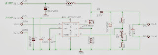
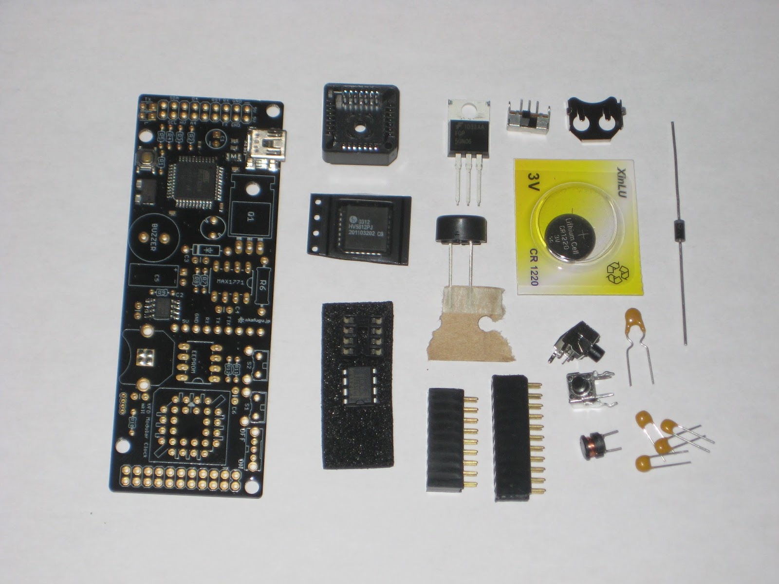
Akafugu's VFD Version 1 clock uses the same MAX1771, to generate a lower 50V (for VFD tubes).

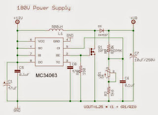
For MK2, Akafugu switched to using MC34063 chip (schematic not published yet).
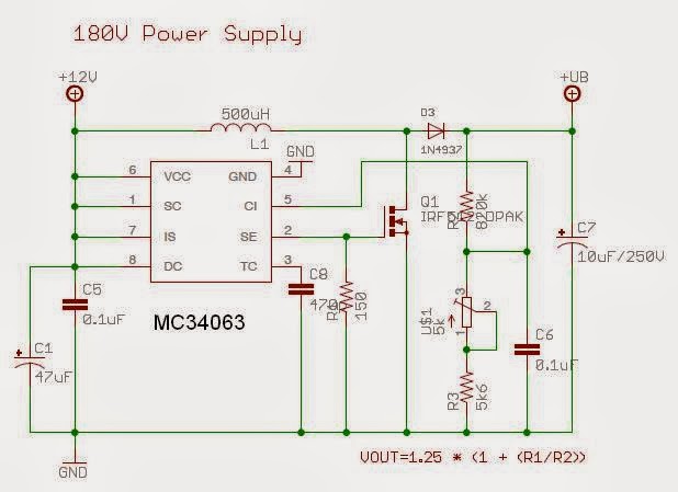
The same chip is also used in their Nixie clock (schematic shown below), to generate 180V. This HV circuit has its own (all SMD) board, which I assembled it myself and worked without a glitch.
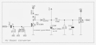
3. Yet others use a PWM pin of a microcontroller. This method requires the processor to be connected and programmed in order to generate the high voltage. The solution is cheap (saves an extra chip), smaller in size (again, one less chip), and also seems to be highly efficient.
Below is the HV schematic used by Adafruit's IceTube clock.

Some of the microcontroller-based boost converters have feedback (close loop, with PWM adjusting to the voltage output, if I am not mistaken), as are those from Cogwheel and Satashnik (shown below, respectively).

As with any analog electronics circuit, troubleshooting a HV supply is not easy. A suitable tool would be an oscilloscope, allowing for the measurement and adjustment of the frequency and pulse width. Once these are cleared, the high voltage could be adjusted usually from the trim pot. To modify the voltage range, try different values for the inductor.

Tubes require high voltage to work. Some (Vacuum Fluorescent Display) need 40V, others (Nixie) 180-200V, and some others (Geiger) even higher, 400-1000V. The high voltages are generated these days by switching-mode power supplies. Essentially, there is only a handful of popular solutions, and each DIY tube kit picks one of these, based on size, power requirements, cost.
In principle, a switching mode power supply, also known as "boost converter", uses a square wave oscillator ("switch") to create magnetic energy in an inductor, then releasing it as high voltage.
Some scientific explanation (with formulas) can be found here, some practical advice (with schematics and photos) here. Adafruit has a very useful online boost calculator.
1. One of the most popular solution for the square wave oscillator is by using the ubiquitous 555. This is inexpensive, but requires some tweaking and adjusting (values of resistors and capacitors). The schematic is standard, but there seem to be a few variations.
The one below is from Ronald Dekker.
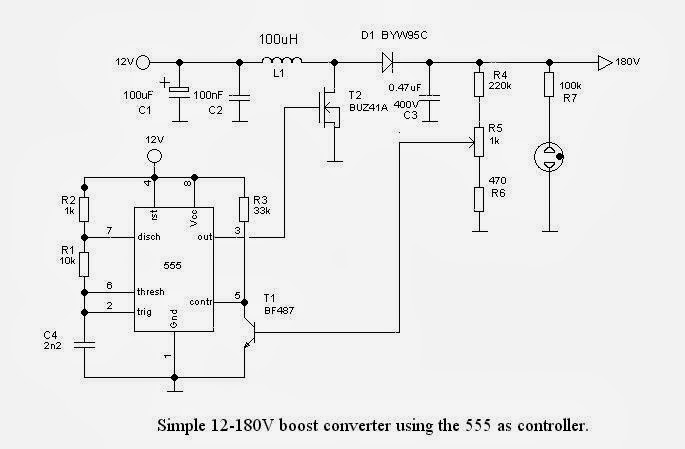
Frank clock (from Pete's Nixie kits) uses an almost identical schematic, but a different set of values for R2-R3- C4 (used for setting the frequency). In the end, the oscillator frequency is about the same at approx 30kHz, calculated with formula f = 1/0.693/C4/(R3+2R2) (in the schematic below).

Same 555 is used in Arduinix, but in a different configuration, although still as astable oscillator. This one has an extra HV capacitor (C4) in series with a resistor (R15), whose exact purpose I don't understand. The oscillation frequency is also weird, according to the above formula, with C3 at 47pF, should be 1.5kHz. No wonder this did not work for me.
Another almost identical HV power supply for Nixie tubes is used in the recently-kickstarted "Nixie tube shield" (for which I pledged $15 for the PCB, and yet to receive it).

And finally, 555 is also used to generate the higher voltages required by Geiger tubes, as used by BroHogan (and MightyOhm). The frequency of oscillation is 4.5kHz (f = 1/R1/C2). (I built several Geiger kits from BroHogan and they were all trouble-free.)
2. Other solutions use specialized chips like MAX1771 and MC34063.
Shown below is the high-efficiency boost converter from Nick de Smith (sold by ogiLumen), based on MAX1771.

Akafugu's VFD Version 1 clock uses the same MAX1771, to generate a lower 50V (for VFD tubes).

For MK2, Akafugu switched to using MC34063 chip (schematic not published yet).
The same chip is also used in their Nixie clock (schematic shown below), to generate 180V. This HV circuit has its own (all SMD) board, which I assembled it myself and worked without a glitch.
3. Yet others use a PWM pin of a microcontroller. This method requires the processor to be connected and programmed in order to generate the high voltage. The solution is cheap (saves an extra chip), smaller in size (again, one less chip), and also seems to be highly efficient.
Below is the HV schematic used by Adafruit's IceTube clock.

Some of the microcontroller-based boost converters have feedback (close loop, with PWM adjusting to the voltage output, if I am not mistaken), as are those from Cogwheel and Satashnik (shown below, respectively).


As with any analog electronics circuit, troubleshooting a HV supply is not easy. A suitable tool would be an oscilloscope, allowing for the measurement and adjustment of the frequency and pulse width. Once these are cleared, the high voltage could be adjusted usually from the trim pot. To modify the voltage range, try different values for the inductor.