Posts with «tool» label

A Usable Arduino Debugging Tool

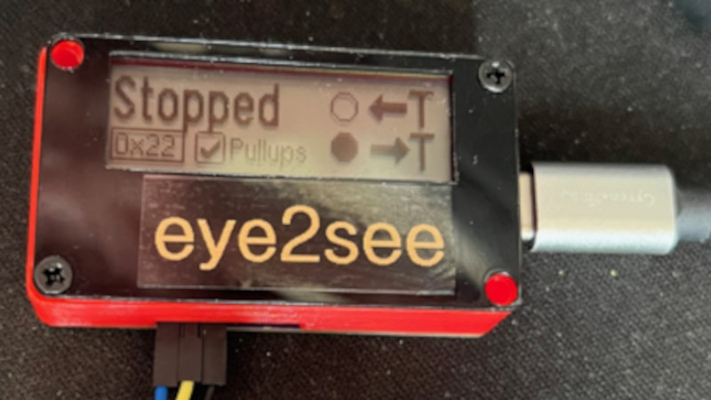
For as popular as the Arduino platform is, it’s not without its problems. Among those is the fact that most practical debugging is often done by placing various print statements throughout the code and watching for them in the serial monitor. There’s not really a great way of placing breakpoints or stepping through code, either. But this project, known as eye2see, hopes to change that by using the i2c bus found in most Arduinos to provide a more robust set of debugging tools.

The eye2see software is set up to run on an Arduino or other compatible microcontroller, called the “probe”, which is connected to the i2c bus on another Arduino whose code needs to be debugged. Code running on this Arduino, which is part of the eye2see library, allows it to send debugging information to the eye2see probe. With a screen, the probe can act as a much more powerful debugger than would otherwise typically be available, being able to keep track of variables in the main program, setting up breakpoints, and outputting various messages on its screen.

The tool is not without its downsides, though. The library that needs to run on the host Arduino slows down the original program significantly. But for more complex programs, the tradeoff with powerful debugging tools may be worth it until these pieces of code can be removed and the program allowed to run unencumbered. If you’d like to skip needing to use a second Arduino, we’ve seen some other tools available for debugging Arduino code that can run straight from a connected PC instead.

Hack a Day 31 Jul 19:30

Pressure Gauge Built In A Vacuum

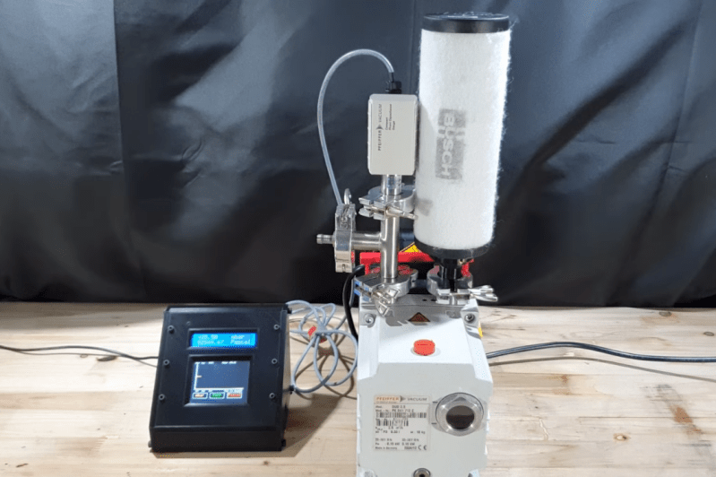
Necessity might be the mother of all invention, but we often find that inventions around here are just as often driven by expensive off-the-shelf parts and a lack of willingness to spend top dollar for them. More often than not, we find people building their own tools or parts as if these high prices are a challenge instead of simply shrugging and ordering them from a supplier. The latest in those accepting the challenge of building their own parts is [Advanced Tinkering] who needed a specialty pressure gauge for a vacuum chamber.

In this specific case, the sensor itself is not too highly priced but the controller for it was the deal-breaker, so with a trusty Arduino in hand a custom gauge was fashioned once the sensor was acquired. This one uses an external analog-to-digital converter to interface with the sensor with 16-bit resolution, along with some circuitry to bring the ~8 V output of the sensor down to the 5 V required by the microcontroller. [Advanced Tinkering] wanted a custom live readout as well, so a 3D printed enclosure was built that includes both an LCD readout of the pressure and a screen with a graph of the pressure over time.

For anyone else making sensitive pressure measurements in a vacuum chamber, [Advanced Tinkering] made the project code available on a GitHub page. It’s a great solution to an otherwise overpriced part provided you have the time to build something custom. If you’re looking for something a little less delicate, though, take a look at this no-battery pressure sensor meant to ride along on a bicycle wheel.

Hack a Day 23 Feb 16:30

Tachometer Uses Light, Arduinos

To measure how fast something spins, most of us will reach for a tachometer without thinking much about how it works. Tachometers are often found in cars to measure engine RPM, but handheld units can be used for measuring the speed of rotation for other things as well. While some have mechanical shafts that must make physical contact with whatever you’re trying to measure, [electronoobs] has created a contactless tachometer that uses infrared light to take RPM measurements instead.

The tool uses an infrared emitter/detector pair along with an op amp to sense revolution speed. The signal from the IR detector is passed through an op amp in order to improve the quality of the signal and then that is fed into an Arduino. The device also features an OLED screen and a fine-tuning potentiometer all within its own self-contained, 3D-printed case and is powered by a 9 V battery, and can measure up to 10,000 RPM.

The only downside to this design is that a piece of white tape needs to be applied to the subject in order to get the IR detector to work properly, but this is an acceptable tradeoff for not having to make physical contact with a high-speed rotating shaft. All of the schematics and G code are available on the project site too if you want to build your own, and if you’re curious as to what other tools Arduinos have been used in be sure to check out the Arduino-based precision jig.

Tiny Hotplate Isn’t Overkill

When working on a new project, it’s common to let feature creep set in and bloat the project. Or to over-design a project well beyond what it would need to accomplish its task. Over at Black Mesa Labs, their problem wasn’t with one of their projects, it was with one of their tools: their hot plate. For smaller projects, an 800W hot plate was wasteful in many ways: energy, space, and safety. Since a lot of their reflow solder jobs are on boards that are one square inch, they set out to solve this problem with a tiny hot plate.

The new hot plate is perfectly sized for the job. Including control circuitry, it’s around the size of a credit card. The hot plate is powered from a small surplus 20V 5A laptop power supply and does a nice 4 minute reflow profile and cools off completely in under a minute. Compared to their full-sized hot plate, this is approximately 29 minutes faster, not to mention the smaller workspace footprint that this provides. The entire setup cost about $20 from the heating element to the transistors and small circuit board, and assuming that you have an Arduino Pro sitting in your junk bin.

It’s a good idea to have a reflow oven or a hot plate at your disposal, especially if you plan to do any surface mount work. There are lots of options available, from re-purposed toaster ovens to other custom hot plates of a more standard size. Overkill isn’t always a bad thing!


Filed under: tool hacks
Hack a Day 01 Apr 16:31

Link Trucker is a Tiny Networking Giant

If you’re a networking professional, there are professional tools for verifying that everything’s as it should be on the business end of an Ethernet cable. These professional tools often come along with a professional pricetag. If you’re just trying to wire up a single office, the pro gear can be overkill. Unless you make it yourself on the cheap! And now you can.

[Kristopher Marciniak] designed and built an inexpensive device that verifies the basics:

  • Is the link up? Is this cable connected?
  • Can it get a DHCP address?
  • Can it perform a DNS lookup?
  • Can it open a webpage?

What’s going on under the hood? A Raspberry Pi, you’d think. A BeagleBoard? Our hearts were warmed to see a throwback to a more civilized age: an ENC28J60 breakout board and an Arduino Uno. That’s right, [Kristopher] replicated a couple-hundred dollar network tester for the price of a few lattes. And by using a pre-made housing, [Kristopher]’s version looks great too. Watch it work in the video just below the break.

Building an embedded network device used to be a lot more work, but it could be done. One of our favorites is still [Ian Lesnet’s] webserver on a business card from way back in 2008 which also used the ENC28J60 Ethernet chip.


Filed under: Network Hacks, tool hacks

Quasi real-time oscilloscope: REMIX

 Updated on 21 Sept. 2012, version 4.

 Updated on 15 Oct. 2012, version 5.

Recently I was reviewing one of my oldest project, and decided to “refresh” previous design by taking full advantage of the new arduino Leonardo board.  Based on AtMega32U4, which include PGA (programmable gain amplifier), oscilloscope’s  analog front end doesn’t require external OPA this time, end could be build in 1-2 hours on prototype board, using 5 resistors, 5 capacitors and one IC. Short specification:

  • Four channels.
  • Switchable gain settings 1x, 10x, 40x, 200x.

Hardware.

 As you can see on drawings above, inputs are AC coupled with caps, and biased with 1.25V generated by LM317. Connector for other two inputs not installed yet.

Software.

Project keeps almost same  structure of commands (CLI – command line interface) as its ancestor, with only two new for channel and gain selection. Read comments, it explains how to use them. One more things, I removed “r” – re-print option from the list of available commands.

Have fun!.

Link to arduino Leonardo sketch:  Oscilloscope_Leonardo.

********************************************* Version 4*********************************************

 Well, even posted above sketch has low complexity, and its good for beginning, nevertheless it’s quite limited as measuring device. The most important feature for oscilloscope, except V/div,  is T/div, or timing, that has to be as much precise as possible.   This is why “standard” timing options based on TIMER1 were add to next version of software. There are 9 time settings Time/div (10 samples):

50ms, 20ms, 10ms, 5ms, 2ms, 1ms, 500us, 200us, 100usec

corresponding to

200Hz, 500Hz, 1kHz, 2kHz, 5kHz, 10kHz, 20kHz, 50kHz, 100kHz

sampling rate. You can choose any of of this in the same manner, entering a digit 1-9 and letter d (display). Zero would skip capture, and just do whatever next letter request. Basically, 0 should be used to print channels data from memory. Combination: 9d0i – capture at 100 kHz rate, print chart and info-table,
4c2g7d – select 4-th channel, set gain to 10, select 20 kHz sampling rate and display.

I also add multichannel sampling capability. Commands 2m, 3m or 4m would configure oscilloscope for 2, 3 or 4 channels simultaneously capturing input waveform.   As arduino has only 1 ADC, switching in multichannel mode would reduce sampling rate proportionally to number of channels, and this changes would be reflected in right top corner of the display. What more, arduino would automatically change vertical resolution per channel, to fit all 2 – 4 charts on one screen!

Known caveats:

  • Sampling rate 9, or 100 usec per division (10 usec per sample) could not be selected in multichannel mode, should be in use for single channel only (1m, 1c – 2c – 3c – 4c).
  • There is a “shift” in channel number, signal  presented at input 1 would show up on screen 2, and so on. This happens on time settings 7 (occasionally), 8 and 9 in 4x multichannel mode due delay in MUX registers switching. Shouldn’t be an issue for 2x channel mode, or when you have an “overview” of the signals shape in single channel mode (1m) before switching to 4x, so you would know what to expect at each input port.

Link to arduino Leonardo sketch:  Oscilloscope_LeonardoV4

********************************************* Version 5*********************************************

 New updated version. I was thinking how to improve simplest ever oscilloscope, and have made some structural changes in the code, mostly related to sampling in multichannel mode.

First of all, instead of “delay” 2 microseconds, that was used to give a multiplexer (and PGA amplifier) time to “settle” on new channel, I decided not to waste a time (that may be priceless in real-time application), rather start new conversion, than track samples based on the “history” of MUX settings, and store new sample in corresponding two dimensional array box. Now MUX and PGA would have more time,  and consequently I could reduce ADC pre-selector’s clock to get better readings. It solved all the problems with wrong association port number and picture on the screen.

Secondly,  as you, probably, already notice I’ve been working on another project recently, where phase is a PRIME factor of the whole idea of the design. Phase noise is a jitter, and it degrades  spatial resolution and the sensitivity of the sound localization.  Jitter always would be presented in the incoming signal – sampled waveform due “not synchronous” way of sampling, as “start new conversion” events were generated in “manual” mode. As microprocessor spend different amount of time to get inside of the ISR (interrupt subroutine) depends on where it was interrupted, time frame of the events, basically, was not defined. In order to get rid off the phase noise, I changed ADC settings to be triggered via TIMER 1. There is a code:

ADCSRA = ((1<< ADEN)| // 1 = ADC Enable
(0<< ADSC)| // 1 = ADC Start Conversion
(1 <<ADATE) | / / 1 = ADC Auto Trigger Enable
*****
ADCSRB = ((1<<ADHSM)| // High Speed mode select
(0<< MUX5)| // 0 (10100) ADC1<->ADC4 Gain = 1x.
(0<<ADTS3)|
(1 <<ADTS2) | / / Sets Auto Trigger source Timer/Counter1 Compare Match B
(0 <<ADTS1) |
(1 <<ADTS0) );

For some unknown for me reason, Atmel designed TIMER 1 channel B to be an auto trigger source of the ADC, the same time to run TIMER 1 itself in CTC mode, channel A must be set. I simply “bind” two channels A and B in “parallel”, so both of them rise interrupt flag at the same moment, only A re-starts a TIMER 1, and B generates “start new conversion” event and calling ISR for “maintenance” – take a new sample waiting in the line and switch a MUX to another channel of the oscilloscope.

uint8_t take_it( int fast )
{
   ADCSRA &= 0xF8;
   if ( multChan -1 )
   {
    switch( fast ) { 
       case 7: // 20 kHz / 
         ADCSRA |= 0×03; 
         break; 
       case 8: // 50 kHz / 
         ADCSRA |= 0×02; 
         break; 
       case 9: // 100 kHz / 
         Serial.print(F(“\n\t *** NOT SUPPORTED ***”));
         return 0;
        default:
        ADCSRA |= 0×04;
       }
     }
    else
    { 
     switch( fast ) { 
        case 6: // 10 kHz / 
          ADCSRA |= 0×06; 
          break; 
        case 7: // 20 kHz / 
          ADCSRA |= 0×05; 
          break; 
        case 8: // 50 kHz / 
          ADCSRA |= 0×04; 
          break; 
        case 9: // 100 kHz / 
          ADCSRA |= 0×03; 
          break; 
        default:
          ADCSRA |= 0×07;
        }
      }
OCR1A   = smplTime[fast -1];
OCR1B   = smplTime[fast -1];
TCNT1   = 0;
TIFR1    |= (1<<OCF1B); 
TIMSK1 |= (1<<OCIE1B);
   flagSamp = 0; 
   while ( !flagSamp );
   for ( uint8_t indx, y = 0; y < multChan; y++){
      if ( multChan -1) indx = y;
      else indx = chanNumb;
   for ( int i = 0; i < INBUF; i++){
      if ( x[indx][i] & 0×0200) x[indx][i] += 0xFE00; // Convert to negative 16-bit word (2′s comp)
      else x[indx][i] += 0×200;
      }
     }
  return 1;
}
ISR(TIMER1_COMPB_vect)
{
   static uint8_t n_sampl = 0;
   static uint8_t history = 0;
   x[history][n_sampl] = ADC;
    history = chanNumb; 
   if ( multChan -1 )
   { 
    chanNumb++;
    if ( chanNumb >= multChan )
      {
       chanNumb = 0;
       n_sampl++;
      }   
     ADMUX &= 0xFC;
     ADMUX |= chanNumb; 
    }
   else
   {
     n_sampl++;
    }
   if ( n_sampl >= INBUF )
    {
      flagSamp = 1;
      n_sampl = 0;
TIMSK1 &= ~(1<<OCIE1B);
   }
}

Oscilloscope_Leonardo_V5.

The only issue that not solved yet, is a sampling in multichannel mode in “9″ T/div. Probably, Atmel just was not design to do such things…