Posts with «rfid» label

Arduino based Security Project Using Cayenne


Description

This is an Arduino based home security project that uses the power of "Cayenne" for extraordinary capabilities.

Cayenne Beta

Cayenne is a new IoT drag and drop platform originally released for the Raspberry Pi, but now available for Arduino. Cayenne makes the task of connecting your Arduino to the internet as simple as possible. All of the complexity of internet connectivity is hidden within the Cayenne library.

You can easily create a Network of Arduinos and build an IoT system which can be managed and operated within the Cayenne dashboard. This dashboard is accessible through your browser or via the Cayenne smart phone app (on IOS or Android).

The feature I liked the most, was the ability to change the position of sensors or actuators on the Arduino without having to re-upload Arduino code. I could manage the changed position from within the Cayenne platform. The other feature that I liked was the ability to setup actions based on custom triggers. You can use Cayenne to trigger a whole range of functions, for example: play a sound, move a motor, light up an LED, or to send alert notifications via email or SMS.

Cayenne is in Beta at the moment, so there are a few minor bugs here and there, but overall - I give it a thumbs up - it is definitely worth checking out.
 

Here is a link to the Cayenne Beta Program:
**Cayenne Beta Link**


              Source: myDevices Media Kit


Home Security Project Summary

In order to fully experience this new IoT platform, I decided to create a project to really put it through its paces. This is what my Security Project will need:

  1. It will use two Arduinos, one connected to the internet via an Ethernet shield, and the other via WIFI.
  2. Two detectors - a PIR sensor and a laser trip wire.
  3. If the sensors are tripped, the person has 10 seconds to present an RFID tag to the Grove RFID reader:
    • If a valid RFID tag is SUCCESSFULLY presented within the time limit, a nice personalised greeting will be played to that person using a Grove - Serial MP3 player
    • If a valid RFID FAILS to be presented within the time limit, an Alarm will sound, and I will be notified of the intrusion via an SMS alert.
  4. The Cayenne dashboard will show the status of the sensors, and I will have full control over my security system via the web interface (or smartphone app).
  5. The sensors will be attached to a different Arduino to that of the Grove MP3 player and the RFID tag reader, which means that there will have to be some level of communication between the two Arduinos. In fact, the cross communication will be vital to the success of this project.


Project Video


Flow Diagrams:

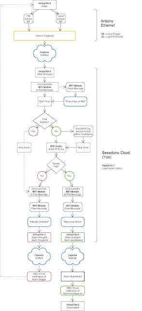
Main Flow Diagram

The following flow diagram shows the Security project process. It is a high level view of the decisions being made by each Arduino in response to various events.  


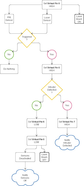
Triggers Flow Diagram

The following flow diagram aims to highlight the various triggers set up within Cayenne to get this Security system to work.  


Arduino IDE and Library Downloads

You will need an Arduino IDE to upload code to the Arduino and the Seeeduino Cloud.
Here is the link to the Arduino IDE: Arduino IDE - download location

The Cayenne service requires that you download and install the Cayenne Library into your Arduino IDE.
You can get the Cayenne Library from here: Cayenne Library File - Download


Cayenne Connectivity Setup

The Seeeduino Cloud needs to be prepared for use with Cayenne.
Normal operating/setup instructions can be found here: Seeeduino Cloud WIKI page
 
Once you have successfully connected Seeeduino Cloud to your WIFI network, you can add it to the Cayenne Dashboard by making the following selections from within the Cayenne Web application:

  1. Add New
  2. Device/Widget
  3. Microcontrollers
  4. Arduino
  5. Ensure Seeeduino Cloud is connected to WIFI network - the select the NEXT button
  6. Select - Arduino Yun: Built-in Ethernet - ticked
  7. Providing you have already installed the Cayenne library as described above - you should be able to copy and paste the code to the Arduino IDE and upload to the Seeeduino Cloud.
  8. If successful, you should see the Arduino Yun board appear within the Cayenne Dashboard. If not, then seek help within the Cayenne forum.


The Arduino UNO with WIZNET 5100 - Ethernet Shield
also needs to be prepared with Cayenne

  1. Add New
  2. Device/Widget
  3. Microcontrollers
  4. Arduino
  5. Ensure Arduino is powered, and Ethernet shield is connected to your internet router via an Ethernet cable
  6. Select - Arduino Uno: Ethernet Shield W5100 - ticked
  7. Copy and paste the code to the Arduino IDE and upload to the Arduino UNO.
  8. If successful, you should see the Arduino Uno board appear within the Cayenne Dashboard. If not, then seek help within the Cayenne forum.


If you have the Ethernet shield with the WIZNET 5200 chip, then you may need to download a specific Ethernet library in addition to the Cayenne library.
 
Just follow the instructions within the Automatically generated sketch provided - when you select your specific Arduino/Ethernet/WIFI shield combination. If you need further instructions on connecting your device to Cayenne - then please visit the myDevices website for the online documentation.


ARDUINO CODE (1)


Code for Arduino UNO with Ethernet Shield:

The following code will need to be uploaded to the Arduino UNO:


ARDUINO CODE (2)


Code for Seeeduino Cloud:

The following code will need to be uploaded to the Seeeduino Cloud:


Fritzing diagram (1)


Fritzing diagram for Arduino UNO with Ethernet

Please click on the picture below for an enlarged version of this fritzing diagram


Fritzing diagram (2)


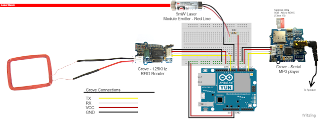
Fritzing diagram for Seeeduino Cloud

Please click on the picture below for an enlarged version of this fritzing diagram


Cayenne Dashboard Setup - GUI


The Arduino code only provides half of the functionality of this project. The Cayenne Dashboard needs to be setup to provide the rest of the functionality. The following instructions will show you how to add each of the widgets required for this Home Security project.


Arduino Ethernet - Master Switch

The master switch allows me to turn the security system on and off. When I turn the MASTER SWITCH ON, the laser beam will turn on, and the sensors will start monitoring the area for intruders. This widget is NOT associated with a physical switch/sensor on the Arduino - it uses virtual channel 0. We need to add the Master switch to the dashboard:


  1. Add New
  2. Device/Widget
  3. Actuators
  4. Generic
  5. Digital Output - Control a Digital Output
  6. Widget Name: Master On Off Switch
  7. Select Device: Arduino Ethernet
  8. Connectivity: Virtual
  9. Pin: V0
  10. Choose Widget: Button
  11. Choose Icon: Valve
  12. Step2: Add Actuator
We will add a trigger later to get this button to automatically turn the Laser beam on.


Arduino Ethernet - PIR Sensor

This sensor will be used to detect movement in the room. If a person walks into the room, this sensor will detect movement, and will trigger a message to be played on the Grove Serial MP3 player. The message will aim to get the person to identify themselves. They identify themselves by placing their RFID tag in close proximity to the Grove RFID reader. If the tag is valid, a "Welcome home" message is played on the Grove MP3 player. If a valid tag is not presented to the reader within 10 seconds, an Alarm will go off ("Alarm sound" played on Grove MP3 player.)

The PIR sensor is connected to digital Pin 6 of the Arduino, however, it is mapped to virtual pin 1 for better synchronisation with the Cayenne dashboard. This was done to capture ALL detections - as the PIR sensor could change from a LOW to HIGH and back to LOW state in between a Cayenne state check - and therefore, Cayenne could miss this motion detection.. Therefore we need to assign the PIR sensor to a virtual channel in the following way:
  1. Add New
  2. Device/Widget
  3. Sensors
  4. Motion
  5. Digital Motion Sensor - Motion Detector
  6. Widget Name: PIR sensor
  7. Select Device: Arduino Ethernet
  8. Connectivity: Virtual
  9. Pin: V1
  10. Choose Widget: 2-State Display
  11. Choose Icon: Light
  12. Step2: Add Sensor
  13. Select Settings from the PhotoResistor
  14. Choose Display: Value
  15. Save


Arduino Ethernet - Photoresistor

This sensor will be used with the laser beam to create a laser tripwire. If the sensor detects a change in light levels (drops below the threshold), it will activate the laser trigger button on the dashboard. The person will then be required to identify themselves etc etc (similar to the motion detection by the PIR sensor). The photoresistor widget will display the raw analog reading from the sensor (connected to A2), but is associated with virtual channel 2. I used a virtual channel for more control over this sensor. To add the Photoresistor to the dashboard:

  1. Add New
  2. Device/Widget
  3. Sensors
  4. Luminosity
  5. Photoresistor - Luminosity sensor
  6. Widget Name: PhotoResistor
  7. Select Device: Arduino Ethernet
  8. Connectivity: Virtual
  9. Pin: V2
  10. Choose Widget: Value
  11. Choose Icon: Light
  12. Step2: Add Sensor


Arduino Ethernet - Laser Trigger

The laser trigger is just an indicator that someone tripped the laser beam. The state of this widget is used to notify the Seeeduino that a presence has been detected. This widget is associated with virtual pin 4 on the Arduino UNO with Ethernet.

  1. Add New
  2. Device/Widget
  3. Actuators
  4. Generic
  5. Digital Output - Control a Digital Output
  6. Widget Name: Laser Trigger
  7. Select Device: Arduino Ethernet
  8. Connectivity: Virtual
  9. Pin: V4
  10. Choose Widget: Button
  11. Choose Icon: Lock
  12. Step2: Add Actuator


Arduino Ethernet - Laser Threshold

The laser threshold is used to manually configure the light level at which the laser trigger will trip. When the photoresistor value drops below the threshold value, the laser trigger icon will activate. This allows the threshold value to be updated from the Cayenne dashboard, rather than having to manually adjust the value in the Arduino code. Also, this threshold can be set remotely, in that you don't have to be near the Arduino to change this value. A very useful feature of this Security system. This widget is associated with virtual pin 5 on the Arduino UNO with Ethernet.

  1. Add New
  2. Device/Widget
  3. Actuators
  4. Generic
  5. PWM Output - Control a PWM Output
  6. Widget Name: Laser Threshold
  7. Select Device: Arduino Ethernet
  8. Connectivity: Virtual
  9. Pin: V5
  10. Choose Widget: Slider
  11. Slider Min Value: 0
  12. Slider Max Value: 10
  13. Step2: Add Actuator
The max value of the slider is 10 - due to a current bug in the Cayenne software. Once resolved, this value (as well as the relevant Arduino code) will need to be updated.


Seeeduino Cloud - Presence Detected

The presence detected widget is there to notify the Seeeduino Cloud that a presence has been detected on the Arduino Uno with Ethernet shield. When the PIR sensor detects movement or if the laser tripwire is tripped, Cayenne will change the state of the Presence Detected widget from LOW to HIGH. This is used within the Seeeduino Cloud to trigger the message "Place your keys on the Mat"
. If a valid RFID tag is read by the Grove RFID reader, then this widget's state will change back from HIGH to LOW, and the MasterSwitch will be deactivated - turning the Security system off. This widget is associated with Virtual pin 6 on the Seeeduino Cloud.

  1. Add New
  2. Device/Widget
  3. Actuators
  4. Generic
  5. Digital Output - Control a Digital Output
  6. Widget Name: Presence Detected
  7. Select Device: Seeeduino Cloud
  8. Connectivity: Virtual
  9. Pin: V6
  10. Choose Widget: Button
  11. Choose Icon: Lock
  12. Step2: Add Actuator


Seeeduino Cloud - Intruder Alert

If a valid RFID tag is not read by the Grove RFID reader within 10 seconds of a presence detection event, an alarm will sound, and this widget will be activated. This will trigger a notification event - to notify me of the unauthorised intrusion - via SMS or email. I will also have a visual indicator on the Cayenne dashboard that an intrusion has taken place. This widget is associated with Virtual pin 7 on the Seeeduino Cloud.

  1. Add New
  2. Device/Widget
  3. Actuators
  4. Generic
  5. Digital Output - Control a Digital Output
  6. Widget Name: Laser Trigger
  7. Select Device: Seeeduino Cloud
  8. Connectivity: Virtual
  9. Pin: V7
  10. Choose Widget: Button
  11. Choose Icon: Thermometer
  12. Step2: Add Actuator


Seeeduino Cloud - Laser Beam

The laser beam widget was created to allow for full control over the laser beam. The laser beam can be turned on or off from the Cayenne dashboard, and a connected to digital pin 7 on the Seeeduino Cloud.


  1. Add New
  2. Device/Widget
  3. Actuators
  4. Light
  5. Light Switch - Turn On/Off a Light
  6. Widget Name: xLaser Beam
  7. Select Device: Seeeduino Cloud
  8. Connectivity: Digital
  9. Pin: D7
  10. Choose Widget: Button
  11. Choose Icon: Light
  12. Step2: Add Actuator


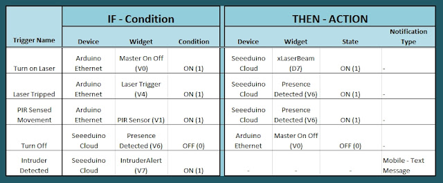
Cayenne Triggers

Now that all of the widgets have been added to the Dashboard, there is just one more step to complete the Security System. We need to setup the triggers. These triggers provide a level of automation that is easy to create within Cayenne, but would be very complicated otherwise. I set my triggers up as per the table below. Each row represents one of the triggers within my Cayenne dashboard. If you would like to see an example of how to add a trigger - please have a look at the video at the top of this tutorial.  


Concluding comments

I used many different elements to put this home/office security project together - Multiple Arduinos were connected to the internet, both controlled by a web/smart phone app, cross-communication/synchronisation between the Arduinos, and the use of multiple sensors and modules including a laser beam !
 
This was way more than just a simple PIR sense and alarm project. I now have a personalised greeting and reminder system when I walk in the door. Everyone else has their own personalised greeting. I can enable my Security System remotely, from two blocks away, and if I wanted to - I could enable it from the other side of the world. I know instantly when someone has entered my house/office.... with an SMS alert straight to my phone.
 
This project could easily be extended:

  1. Press a button on my phone to manually trigger/play a specific message/sound/song
  2. Take a picture of the intruder
  3. Introduce fire or leak detection aswell
  4. Add other environmental sensors - Temperature / Humidity
  5. Connect it to lamp/light - creating a security light
I am sure you can think of more things I could do with this system. In fact, why don't you mention your ideas in the comments below.
 
Cayenne was instrumental in getting this project to work. I don't think I would know where to start if I had to do this project without this cool IoT platform. I think I will definitely be trying out a few more projects using Cayenne, and should you want to do the same, then please make sure to join Cayenne Beta:
 
Here is the link you need to get to the right place: Cayenne Beta Link


If you like this page, please do me a favour and show your appreciation :

 
Visit my ArduinoBasics Google + page.
Follow me on Twitter by looking for ScottC @ArduinoBasics.
I can also be found on Pinterest and Instagram.
Have a look at my videos on my YouTube channel.


ScottC 30 Aug 15:42
alarm  arduino  arduinobasics  cayenne  laser  mp3  mydevices  pir  rfid  security  sms  tutorial  

RFID Lock Keeps Your Bike Safe

What do you do with an RFID chip implanted in your body? If you are [gmendez3], you build a bike lock that responds to your chip. The prototype uses MDF to create a rear wheel immobilizer. However, [gmendez3] plans on building a version using aluminum.

For the electronics, of course, there’s an Arduino. There’s also an RC522 RFID reader. We couldn’t help but think of the Keyduino for this application. When the system is locked, the Arduino drives a servo to engage the immobilizer. To free your rear wheel, simply read your implanted chip. The Arduino then commands the servo to disengage the immobilizer. You can see the system in operation in the video below.

We’ve talked about RFID implants before. Using them as keys for your preferred transportation isn’t a unique idea, of course. Is this is the killer application that makes you want to get chipped? We doubt it, but we admit it is a matter of personal preference.


Filed under: news, security hacks, transportation hacks

Hack Your Cat’s Brain to Hunt For Food

This cat feeder project by [Ben Millam] is fascinating. It all started when he read about a possible explanation for why house cats seem to needlessly explore the same areas around the home. One possibility is that the cat is practicing its mobile hunting skills. The cat is sniffing around, hoping to startle its prey and catch something for dinner. Unfortunately, house cats don’t often get to fulfill this primal desire. [Ben] thought about this problem and came up with a very interesting solution. One that involves hacking an electronic cat feeder, and also hacking his cat’s brain.

First thing’s first. Click past the break to take a look at the demo video and watch [Ben’s] cat hunt for prey. Then watch in amazement as the cat carries its bounty back to the cat feeder to exchange it for some real food.

[Ben] first thought about hiding bowls of food around the house for his cat to find, but he quickly dismissed this idea after imagining the future trails of ants he would have to deal with. He instead thought it would be better to hide some other object. An object that wouldn’t attract pests and also wouldn’t turn rancid over time. The problem is his cat would have to know to first retrieve the object, then return it to a specific place in order to receive food as a reward. That’s where the cat hacking comes in.

[Ben] started out by training his cat using the clicker method. After all, if the cat couldn’t be trained there was no use in building an elaborate feeding mechanism. He trained the cat to perform two separate behaviors, one tiny bit at a time. The first behavior was to teach the cat to pick up the ball. This behavior was broken down into six micro behaviors that would slowly be chained together.

  • Look at the ball
  • Approach the ball
  • Sniff the ball
  • Bite the ball
  • Pick up the ball
  • Pick up the ball and hold it for a few seconds

[Ben] would press on the clicker and reward his cat immediately upon seeing the desired step of each behavior. Once the cat would perform that step regularly, the reward was removed and only given to the cat if the next step in the chain was performed. Eventually, the cat learned the entire chain of steps, leading to the desired behavior.

Next, [Ben] had to teach his cat about the target area. This was a separately trained behavior that was broken down into the following three steps.

  • Look at the target area
  • Approach the target area
  • Sniff the target area

Once the cat learned both of these behaviors, [Ben] had to somehow link them together. This part took a little bit of luck and a lot of persistence. [Ben] would place the ball near the target area, but not too close. Then, he would reward his cat only when the cat picked up the ball and started moving closer to the target area. There is some risk here that if the cat doesn’t move toward the target area at all, you risk extinguishing the old behaviors and they will have to be learned all over again. Luckily, [Ben’s] cat was smart enough to figure it out.

With the cat properly trained, it was time to build the cat feeder. [Ben] used an off-the-shelf electronic feeder called Super Feeder as the base for his project. The feeder is controlled by a relay that is hooked up to an Arduino. The Arduino is also connected to an RFID reader. Each plastic ball has an RFID tag inside it. When the cat places the ball into the target area, the reader detects the presence of the ball and triggers the relay for a few seconds. The system also includes a 315MHz wireless receiver and remote control. This allows [Ben] to manually dispense some cat food should the need arise.

Now whenever the cat is hungry, it can use those primal instincts to hunt for food instead of just having it freely handed over.

[Thanks Dan]


Filed under: home hacks
Hack a Day 08 Aug 18:00
315mhz  arduino  ball  behavior  brain  cat  clicker  control  feeder  food  home  home hacks  hunt  kitten  learn  psychology  remote  rfid  tag  teach  training  

A Tweeting Vending Machine

[Sigurd] manage to obtain an old vending machine from his dorm. The only problem was that the micocontroller on the main board was broken. He and his friend decided they could most likely get the machine back into working order, but they also knew they could probably give it a few upgrades.

This system uses two Arduino Pro Minis and an Electric Imp to cram in all of the new features. One Arduino is connected to the machine’s original main board. The Arduino interfaces with some of the shift registers, relays, and voltage regulators. This microcontroller also lights up the buttons on the machine as long as that particular beverage is not empty. It controls the seven segment LED display, as well as reading the coin validator.

The team had to reverse engineer the original coin validator in order to figure out how the machine detected and counted the coins. Once they figured out how to read the state of the coins, they also built a custom driver board to drive the solenoids.

A second Arduino is used to read NFC and RFID cards using a Mifare RC522 reader. The system uses its own credit system, so a user can be issued a card with a certain amount of pre-paid credit. It will then deduct credit appropriately once a beverage is vended. The two Arduinos communicate via Serial.

The team also wanted this machine to have the ability to communicate with the outside world. In this case, that meant sending cheeky tweets. They originally used a Raspberry Pi for this, but found that the SD card kept getting corrupted. They eventually switched to an Electric Imp, which worked well. The Arduino sends a status update to the Imp every minute. If the status changes, for example if a beverage was dispensed, then the Imp will send a tweet to let the world know. It will also send a tweet to the maintenance person if there is a jam or if a particular slot becomes empty.


Filed under: Arduino Hacks

Coffee Payment System Doesn’t Void Your Warranty

[Oliver] is back with an update to his recent coffee maker hacks. His latest hack allowed him to add a coffee payment system to an off-the-shelf coffee maker without modifying the coffee maker itself. This project is an update to his previous adventures in coffee maker hacking which logged who was using up all of the coffee.

The payment system begins with an Arduino Uno clone inside of a small project enclosure. The Arduino communicates with the coffee maker via serial using the coffee maker’s service port. This port is easily available from outside the machine, so you won’t have to crack open the case and risk voiding your warranty.

The system also includes an RFID reader and a Bluetooth module. The RFID reader allows each user to have their own identification card. The user can swipe their card over the reader and the system knows how many credits are left in their account. If they have enough credit, the machine will pour a delicious cup of coffee.

The Arduino communicates to an Android phone using the Bluetooth module. [Oliver’s] Android app was built using MIT’s app inventor. It keeps track of the account credits and allows the user to add more. The system can currently keep track of up to forty accounts. [Oliver] also mentions that you can use any Bluetooth terminal program to control the system instead of a smart phone app.


Filed under: Arduino Hacks
Hack a Day 28 Dec 03:01

Arduino-Powered Alarm System Has All The Bells And Whistles

Put aside all of the projects that use an Arduino to blink a few LEDs or drive one servo motor. [IngGaro]‘s latest project uses the full range of features available in this versatile microcontroller and has turned an Arduino Mega into a fully-functional home alarm system.

The alarm can read RFID cards for activation and control of the device. It communicates with the front panel via an I2C bus, and it can control the opening and closing of windows or blinds. There is also an integrated GSM antenna for communicating any emergencies over the cell network. The device also keeps track of temperature and humidity.

The entire system can be controlled via a web interface. The Arduino serves a web page that allows the user full control over the alarm. With all of that, it’s hard to think of any more functionality to get out of this tiny microcontroller, unless you wanted to add a frickin’ laser to REALLY trip up the burglars!


Filed under: security hacks
Hack a Day 03 Sep 06:00

Quick and Dirty RFID Door Locks Clean up Nice

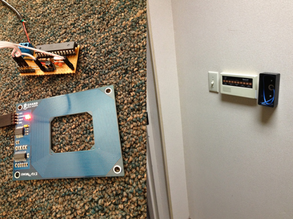
[Shawn] recently overhauled his access control by fitting the doors with some RFID readers. Though the building already had electronic switches in place, unlocking the doors required mashing an aging keypad or pestering someone in an adjacent office to press a button to unlock them for you. [Shawn] tapped into that system by running some wires up into the attic and connecting them to one of two control boxes, each with an ATMega328 inside. Everything functions as you would expect: presenting the right RFID card to the wall-mounted reader sends a signal to the microcontroller, which clicks an accompanying relay that drives the locks.

You may recall [Shawn's] RFID phone tag hack from last month; the addition of the readers is the second act of the project. If you’re looking to recreate this build, you shouldn’t have any trouble sourcing the same Parallax readers or building out your own Arduino on a stick, either. Check out a quick walkthrough video after the jump.


Filed under: Arduino Hacks, Microcontrollers

Upgrade Your Garage Door with Arduino and RFID

[Jason] really wanted to build an RFID controlled garage door opener and decided to turn to Arduino to get the job done. For someone who’s never worked with an Arduino before, he really seemed to know what he was doing.

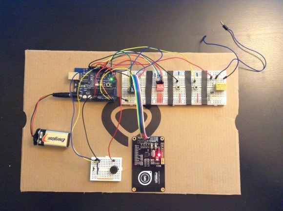
The Arduino acts as the brains of the operation while an off-the-shelf NFC/RFID reader module is used to read the RFID tags. To add new keys to the system, [Jason] simply swipes his “master” RFID key. An indicator LED lights up and a piezo speaker beeps, letting you know that the system is ready to read a new key. Once the new key is read, the address is stored on an EEPROM. From that point forward the new key is permitted to activate the system.

Whenever a valid key is swiped, the Arduino triggers a relay which can then be used to control just about anything. In this case, [Jason] plans to use it to control his garage door. The system also has a few manual controls. First is the reset button. If this button is held down for two seconds, all of the keys from the EEPROM are erased. This button would obviously only be available to people who are already inside the garage. There is also a DIP switch that allows the user to select how long the relay circuit should remain open. This is configurable in increments of 100ms.

For now the circuit is wired up on a couple of breadboards, but it might be a good idea to use something more permanent. [Jason] could always take it a step further and learn to etch his own PCB’s. Or he could even design a board in Eagle CAD and order a real printed board. Don’t miss the video description of the RFID system below.

[via Reddit]


Filed under: Arduino Hacks

Using RFID for a DIY Keepsake Box

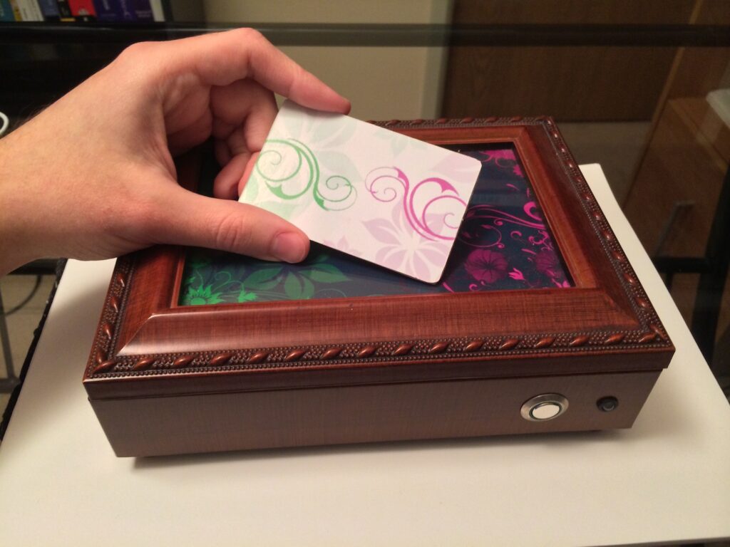
Mike Buss used an Arduino Duemilanove, Parallax RFID reader, micro servo, and piezo electric speaker to make a personalized, lockable keepsake box for his girlfriend’s birthday:

The outside of the box is really simple: it just contains a button and an RGB LED. When she presses the button, the LED lights up green or red depending on if the box is locked. When she waves one of the three personalized RFID cards over the box, a little tune plays and the box unlocks.

As part of the project I also did some cool trick with a Pololu pushbutton power switch to make the battery last a lot longer. Since the Arduino is only powered for a few seconds when listening for RFID tags, the battery lasts a lot longer. When the box is finished locking or unlocking (or after a small time delay), it sends a signal to the power switch to turn off the power and conserve battery life. The box has been running on the same 9V battery I put in 4 years ago!


This smart handbag could stop you from overspending

If you're the sort who overspends at the mall, you may need a firm reminder to watch your budget. How does an ever-vigilant handbag sound? Finder.com.au could soon make one: meet the iBag, a prototype carryall that locks you out if it believes you're going to splurge. The Arduino-powered bag automatically shuts tight at those times you're most likely to shop. Outside of those moments, it uses GPS to warn you when you get too close to favorite stores; ignore the alert and it will both record when you take out your wallet as well as send a text message to a trusted partner. iBag is primarily a publicity stunt meant to highlight the dangers of credit card debt, but it might become a reality. The site is asking potential customers to register their interest, and it may sell both men's and women's versions of the bag for $199 AUD ($173 US) if there's enough demand.

Filed under: GPS, Household

Comments

Source: Finder.com.au

Engadget 30 Jan 09:07