Posts with «access control» label

Building a Hackerspace Entry System

A hackerspace is a place that generally needs to be accessed by a wide group of people, often at weird and unusual hours. Handing around keys and making sure everything is properly locked up can be messy, too. To make it easy for hackers to get in to [Peter]’s local hackerspace, a simple electronic system was whipped up to grant access.

The combined use of QR code & PIN adds a layer of security.

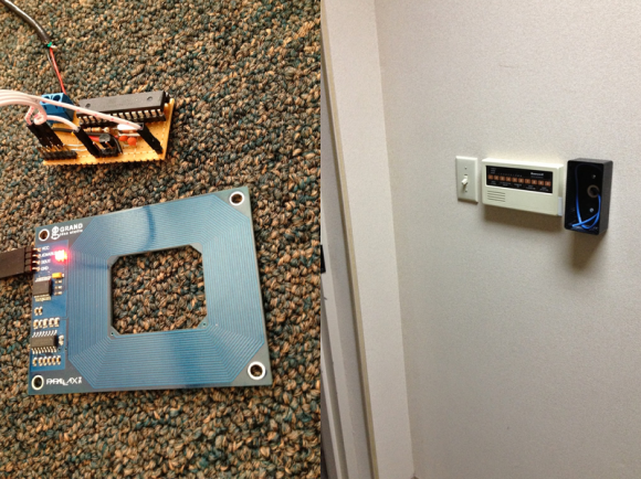
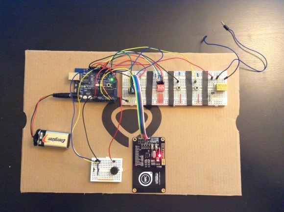
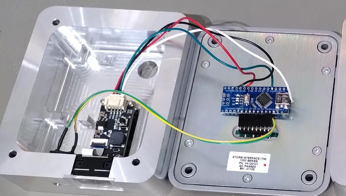
The basic components of the system are a keypad, a QR code and barcode scanner, a stepper motor, an Arduino Nano, and a Raspberry Pi. The keypad is read by an Arduino Nano, which is also responsible for talking to a stepper motor driver to actuate the lock cylinder.

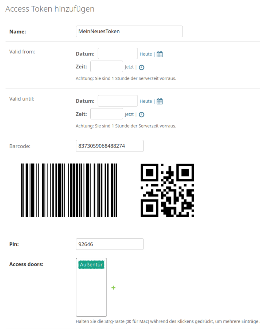
The system works on the basis of two-factor authentication. Regular users authenticate to enter by presenting a QR code or barcode, and entering a matching PIN number. The system can also be set up for PIN-only entry on a temporary basis.

For example, if the hackerspace is running an event, a simple four-digit pin can allow relatively free access for the duration without compromising long-term security. Actual authentication is handled by the Raspberry Pi, which takes in the scanned barcode and/or PIN, hashes it, and checks it against a backend database which determines if the credentials are valid for entry.

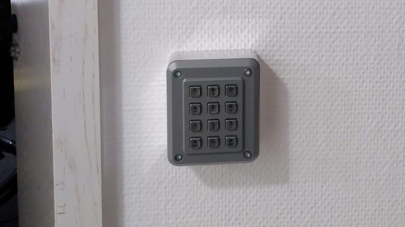
While it’s not technically necessary for a project like this — in fact, you could argue it’s preposterously overkill — we have to take particular note of the machined aluminum enclosure for the keypad. Mere mortals could just run it off on their 3D printers, but if you’ve got access to a CNC router and a suitably chunky piece of aluminum, why not show off a bit?

It’s a nifty system that has served the hackerspace well over some time. We’ve featured some neat access control systems before, too. If you’ve got your own solution to this common problem, don’t hesitate to notify the tipsline!

Quick and Dirty RFID Door Locks Clean up Nice

[Shawn] recently overhauled his access control by fitting the doors with some RFID readers. Though the building already had electronic switches in place, unlocking the doors required mashing an aging keypad or pestering someone in an adjacent office to press a button to unlock them for you. [Shawn] tapped into that system by running some wires up into the attic and connecting them to one of two control boxes, each with an ATMega328 inside. Everything functions as you would expect: presenting the right RFID card to the wall-mounted reader sends a signal to the microcontroller, which clicks an accompanying relay that drives the locks.

You may recall [Shawn's] RFID phone tag hack from last month; the addition of the readers is the second act of the project. If you’re looking to recreate this build, you shouldn’t have any trouble sourcing the same Parallax readers or building out your own Arduino on a stick, either. Check out a quick walkthrough video after the jump.


Filed under: Arduino Hacks, Microcontrollers

Upgrade Your Garage Door with Arduino and RFID

[Jason] really wanted to build an RFID controlled garage door opener and decided to turn to Arduino to get the job done. For someone who’s never worked with an Arduino before, he really seemed to know what he was doing.

The Arduino acts as the brains of the operation while an off-the-shelf NFC/RFID reader module is used to read the RFID tags. To add new keys to the system, [Jason] simply swipes his “master” RFID key. An indicator LED lights up and a piezo speaker beeps, letting you know that the system is ready to read a new key. Once the new key is read, the address is stored on an EEPROM. From that point forward the new key is permitted to activate the system.

Whenever a valid key is swiped, the Arduino triggers a relay which can then be used to control just about anything. In this case, [Jason] plans to use it to control his garage door. The system also has a few manual controls. First is the reset button. If this button is held down for two seconds, all of the keys from the EEPROM are erased. This button would obviously only be available to people who are already inside the garage. There is also a DIP switch that allows the user to select how long the relay circuit should remain open. This is configurable in increments of 100ms.

For now the circuit is wired up on a couple of breadboards, but it might be a good idea to use something more permanent. [Jason] could always take it a step further and learn to etch his own PCB’s. Or he could even design a board in Eagle CAD and order a real printed board. Don’t miss the video description of the RFID system below.

[via Reddit]


Filed under: Arduino Hacks