I wanted to look at the step response of the fan and of the heater, so that I could see if I could derive somewhat reasonable control parameters by theory, rather than by cut-and-try parameter fiddling. Most of the tutorials I’ve looked at give empirical ways of tuning PID controllers, rather than theoretical ones, even ones that use Laplace transforms to explain how PID controllers work and how to determine whether or not the control loop is stable if you are controlling a linear time-invariant system with a known transfer function.
When I first looked at the fan response, I noticed a problem with my tachometer code:

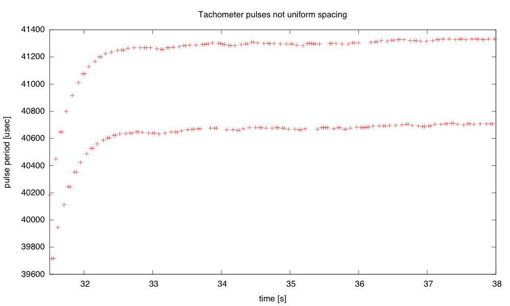
The tachometer gives two pulses per revolution, but the markers used are not perfectly spaced, so I get different estimates of the speed depending which falling-edge-to-falling-edge pulse width I measure. The difference between the two speeds is about 1.6%.
I rewrote the tachometer code to trigger on all four edges of a revolution, and to record the time at each edge in a circular buffer. This way I can use a full revolution of the fan for determining the speed, but get updated estimates every quarter revolution, available in micros_per_revolution:
volatile uint32_t old_tach_micros[4];  // time of last pulses of tachometer
	// used as a circular buffer
volatile uint8_t prev_tach_index=0;    // pointer into circular buffer
volatile uint32_t micros_per_revolution; // most recent pulse period of tachometer

#define MIN_TACH_PULSE  (100)   // ignore transitions sooner than this many
				// microseconds after previous transition

void  tachometer_interrupt(void)
{   uint32_t tach_micros = micros();

    if (tach_micros-old_tach_micros[prev_tach_index] < MIN_TACH_PULSE) return;
    prev_tach_index = (prev_tach_index+1)%4;  // increment circular buffer pointer
    micros_per_revolution= tach_micros-old_tach_micros[prev_tach_index];
    old_tach_micros[prev_tach_index] = tach_micros;
}
In setup(), I need to set up the interrupt with attachInterrupt(FAN_FEEDBACK_INT,tachometer_interrupt, CHANGE);
I think that this improved tachometer code may be a bit too much for first-time programmers to come up with. Circular buffers use a bunch of concepts (arrays, modular arithmetic) and are likely to cause a lot of off-by-one errors. Interrupts alone were a complicated enough concept for students to deal with. I don’t know whether the improvement in speed measurement would be justifiable in the freshman design course.
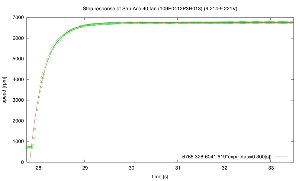
The new tachometer code did smooth out the measurements a lot, though, as expected—it reduces the fluctuation in measured speed to about 0.3%, which is limited by the resolution of the micros() timer I’m using on the Arduino board. I then tried recording some step responses, both for upward steps and downward steps. The upward steps are reasonably approximated by an exponential decay (like a charging curve):

The low speed with PWM=0 (always off) is 724.7 rpm, and the high speed with PWM=255 (always on) is 6766.3rpm. The exponential fit is not perfect, but it is certainly a good enough approximation for designing a closed-loop system.
The response to a downward step, however, is not well modeled by a simple exponential decay:
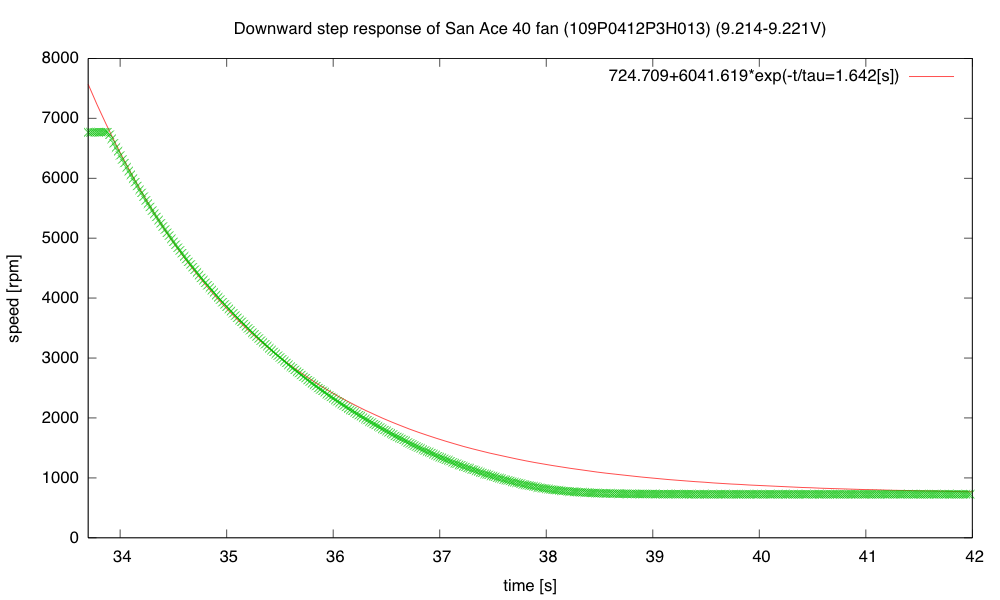
The fan spins down gradually at first (with a time constant about 1.6s), but at low speed the speed changes faster (as if the time constant dropped to about 0.6s).
Note that the fan slows down much more gradually than it speeds up, which means that it is not a linear, time-invariant system. In a linear system, superimposing a step-up and a step-down would cancel, so the responses to the step up and step down should add to a constant value—the fan most definitely does not have that property.
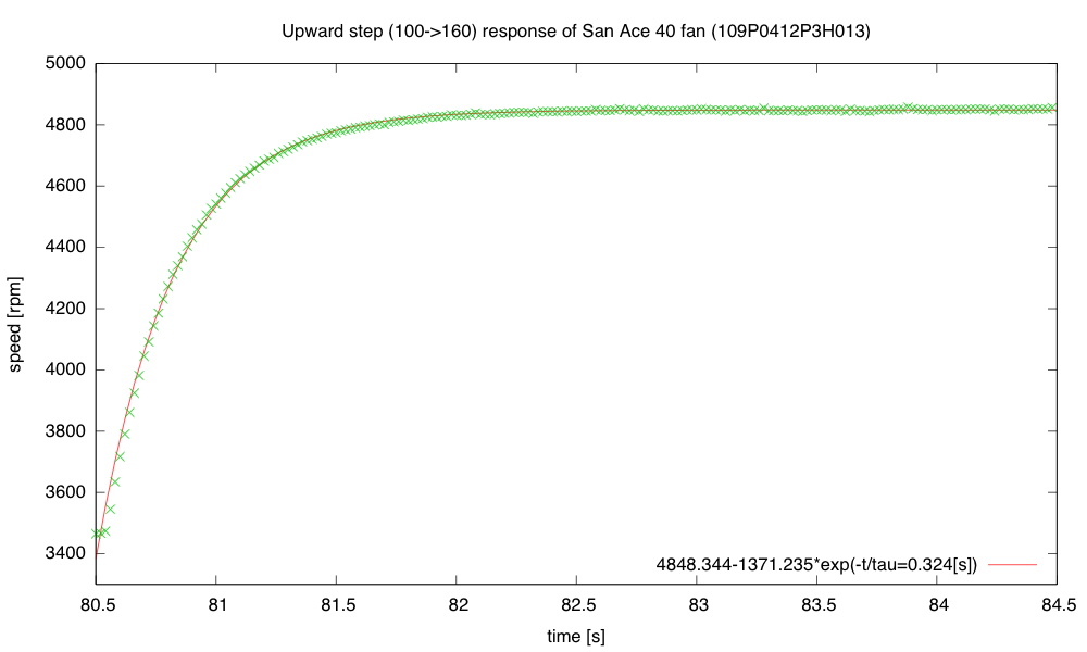
I was curious whether the difference was just apparent for large steps, or also for small ones, so I tried steps between PWM duty cycles of 100/256 and 160/256:

A small upward step is again quick, with almost the same time constant as before.
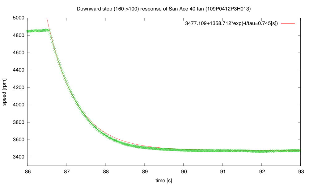
The small downward step is faster than before, though still substantially slower than the upward step of the same size, and with an initially slower response than the final convergence.
I’m going to try writing a couple of ad hoc controllers for the fan, to see if they behave better than the PID controller I’ve been using: open-loop control using just PWM=(setpoint-740)/25; a simple on/off control with a single threshold; hysteresis, using two thresholds instead of 1; PI control with no anti-windup; and a controller that goes to full on or full off when the error is large, to make a quick transition, switching to approximately the right PWM value, when the error is small, with PI control thereafter.
I think that the open-loop controller will have a steady, but wrong speed; the crude on/off controllers will make an audible pulsing of the fan motor; the PI controller will suffer from overshoot when making big steps, and the on/off/PI controller should make nice steps, if I can tune it right.
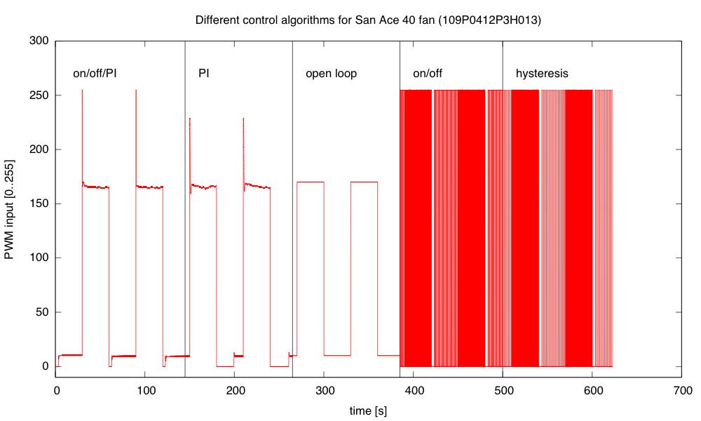
I implemented all the controllers and ran a test switching between setpoints of 1000RPM and 5000RPM every 30 seconds. Here are plots of the behavior with different control algorithms:

The PWM values computed by the various control algorithms show the integrator windup problem for PI clearly after the downward transitions—PI takes a long time to recover from the errors during the downward edge.
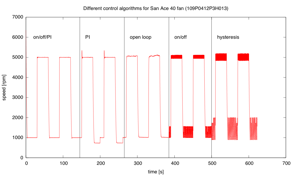
The mixed algorithm does a very good job of control, with little overshoot. The simple PI algorithm has substantial overshoot, particularly when the control loop wants a PWM value outside the range [0,255]. Open loop has significant offset and wanders a bit. On/off control oscillates at about 10hz, and adding hysteresis makes the oscillation larger but slower (about 5Hz).
The errors for the mixed controller are only about ±0.3% and overshoot or ringing at the transitions <40RPM. The simple PI controller overshoots by 340RPM and takes 20 seconds to recover from the integrator windup on the downward transition. The open-loop controller has offset errors of about 1% and a fluctuation of about ±0.7% at the high speed, and an offset of 1% and fluctuations of about ±0.5% at the low speed. The on/off controller has an offset of about 0.5% at high speed with fluctuations of ±2%, and an offset of 28% with fluctuations of ±28%. Adding hysteresis slows down the oscillations, but makes them larger (0.2% offset, fluctuations ±3% at high speed, and 44% offset with fluctuations of ±70% at low speed).The mixed algorithm which uses on/off control for large errors and PI for small errors, with back-calculation of the integral error when switching to the PI controller seems to work very well. But would I be able to get freshmen to the point of being able to develop that themselves within a 2-unit course? Probably not, but I might be able guide them through the development in a series of exercises that started with on/off control, then went to modeling and open-loop control, then the PI control, and finally the mixed control. It would take most of the quarter.
Filed under:
freshman design seminar Tagged:
Arduino,
control loop,
fan,
incubator,
PID controller,
PWM,
tachometer