

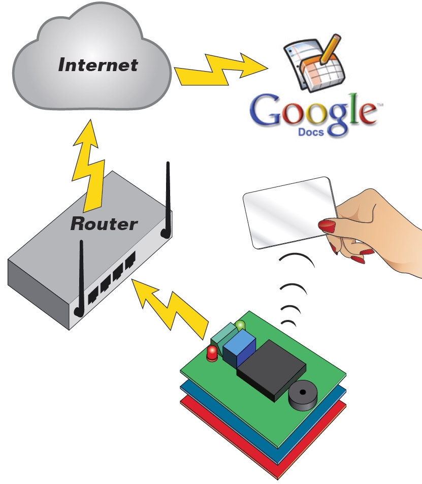
Wi-Fi Body Scale with Arduino
In this post we present the design of a scale that connects to the Internet and automatically sends weight info on a Google Document.
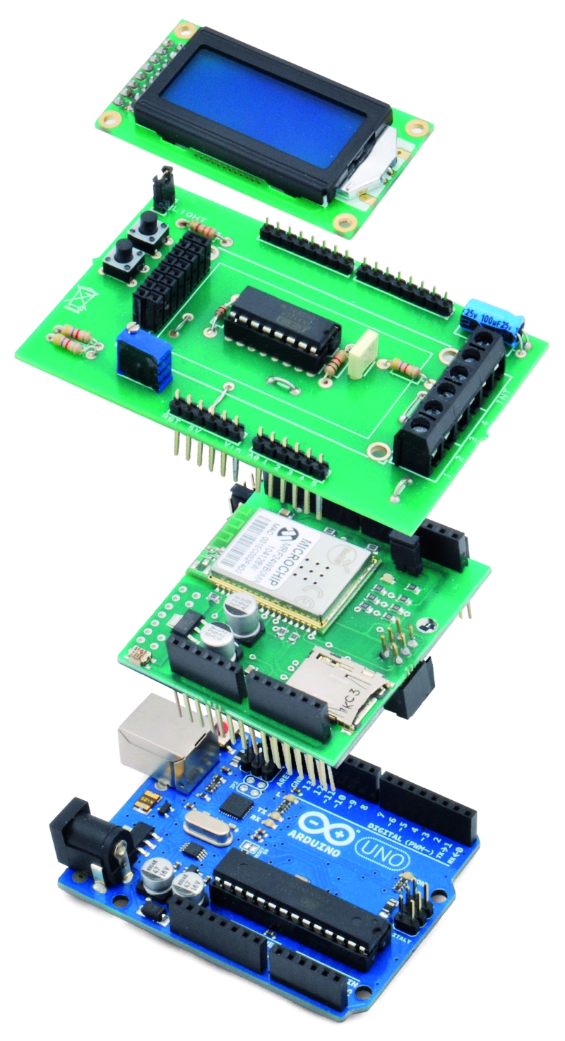
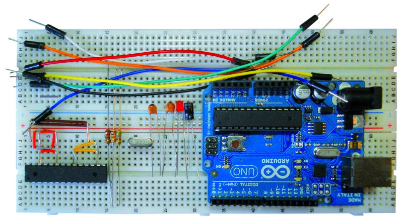
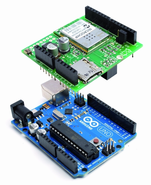
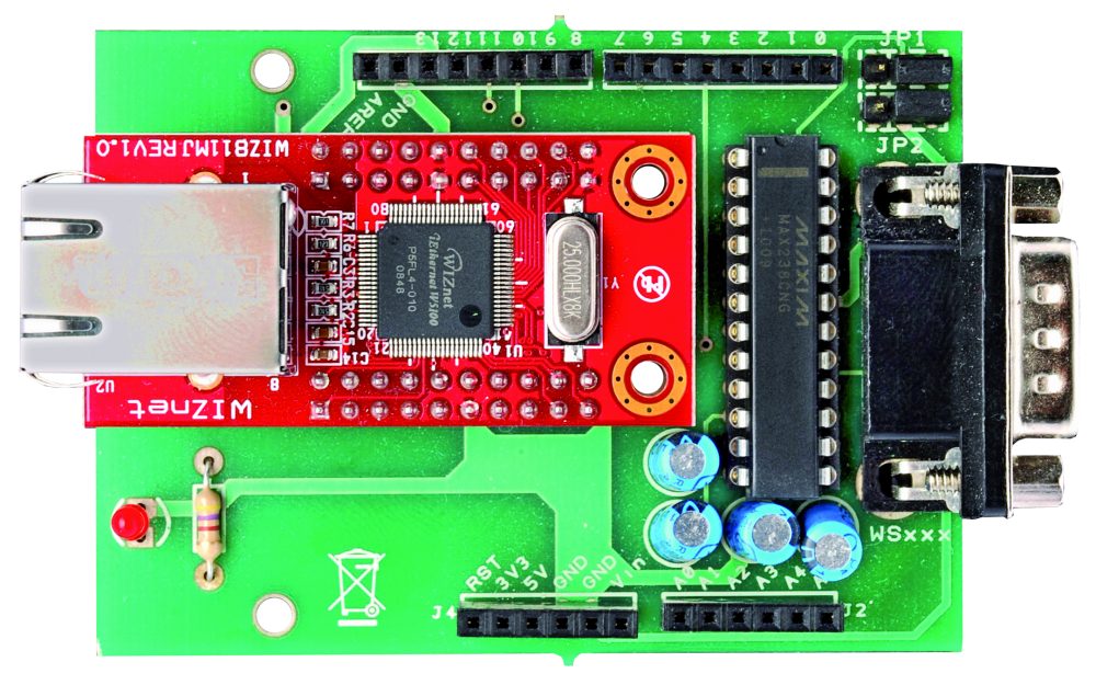
The project is composed of
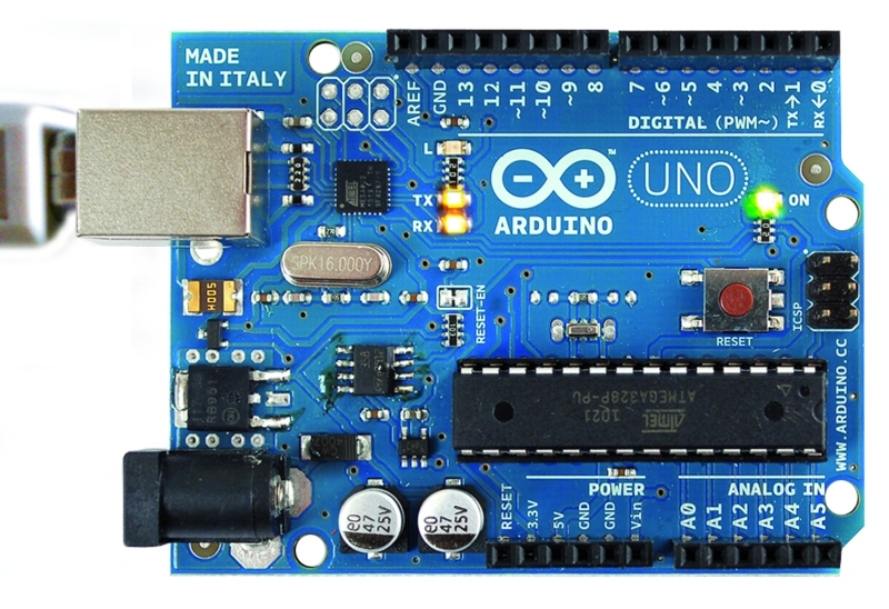
- Arduino Uno board
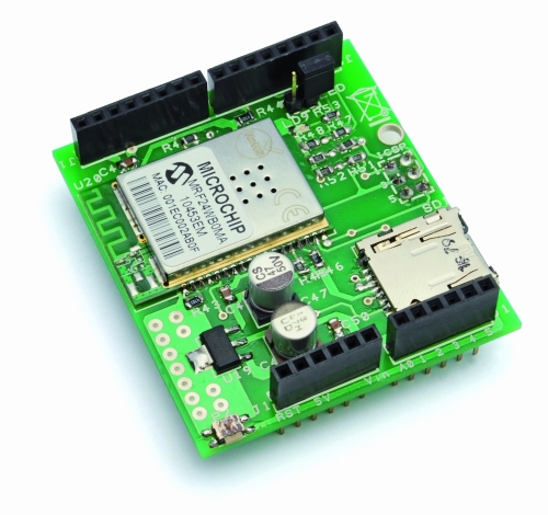
- Wi-Fi shield
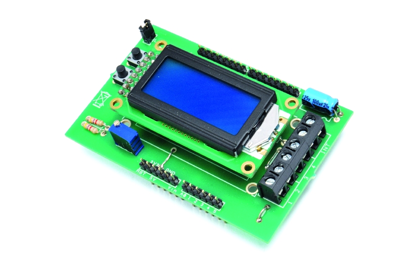
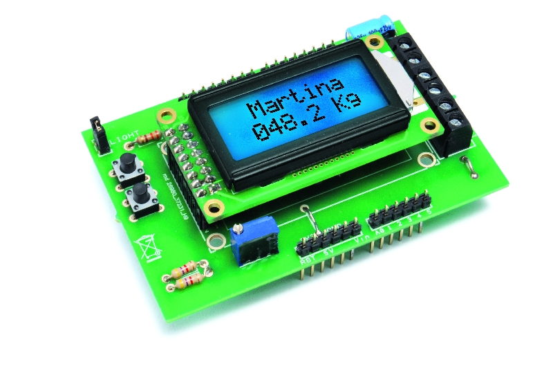
- additional shield that we used to manage data collection and I/O with a clear and comfortable and clear LCD display
- Velleman scale (or another commercial product)
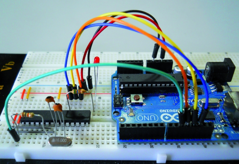
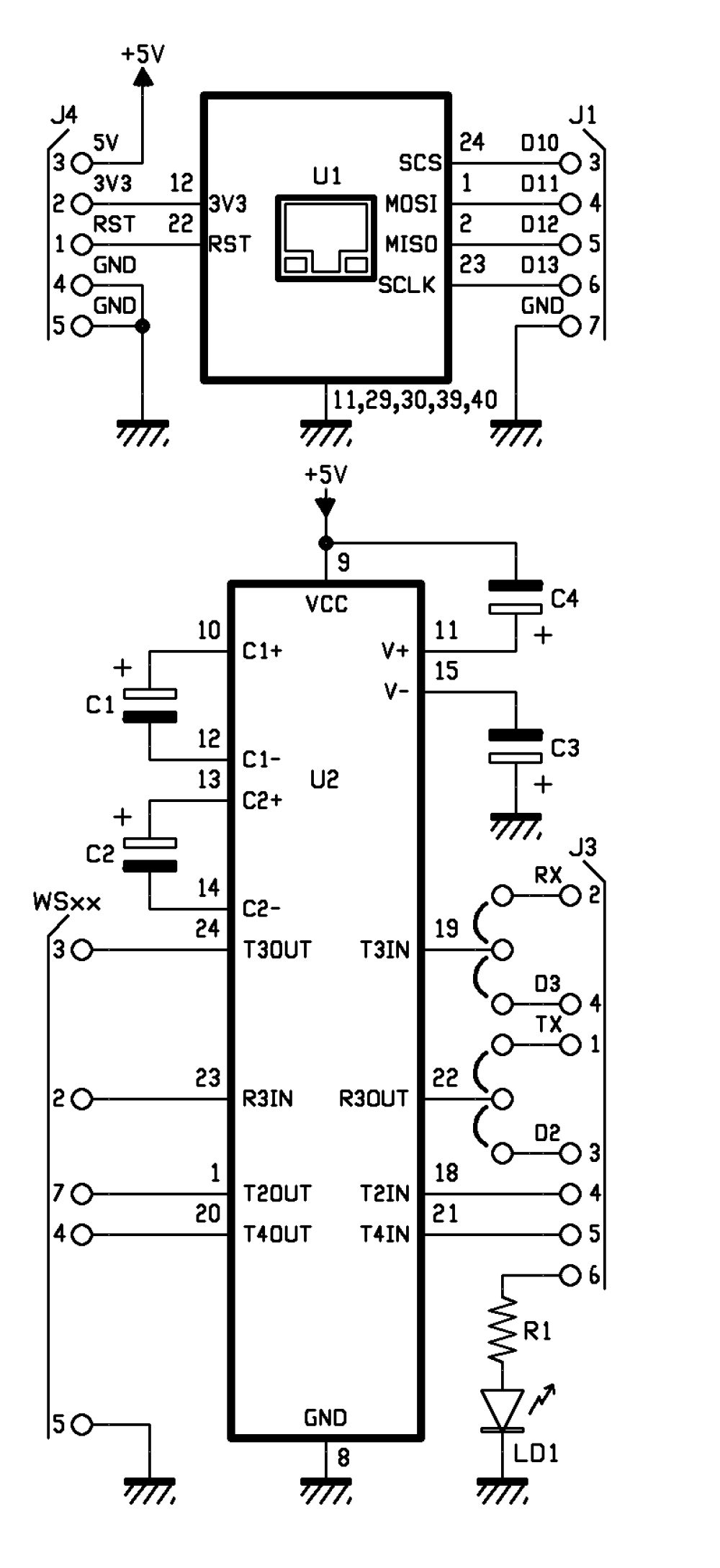
Hardware
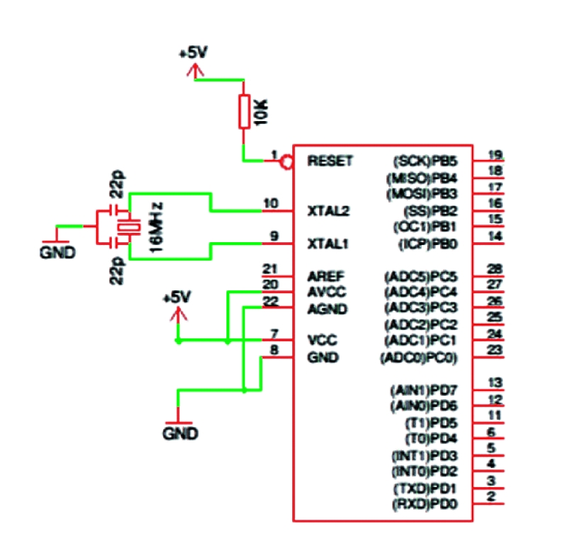
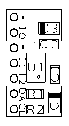
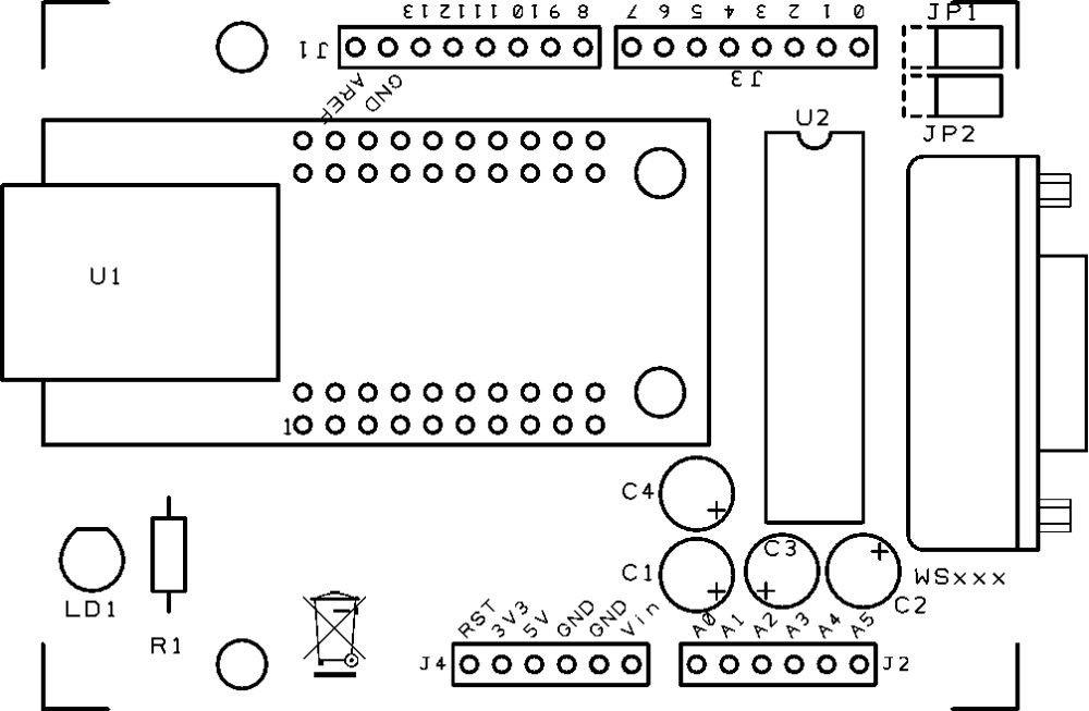
Taking a look at the diagram, we can distinguish three sections:
one for handling digital inputs (two buttons and scale’s switch),
the LCD manager
the analog signal acquisition from load cells
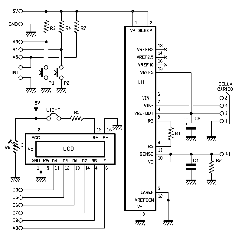
You may notice that P1 and P2 buttons are respectively managed by Arduino’s A3 and A4 inputs (configured as digital), while the INT switch reads the A5 signal (digital as well).
The LCD display used in our project belongs to the family of those based on HD44780 chipset, equipped with seven-pin control (RW, D4, D5, D6, D7, RS and Enable). As you can see from the diagram, RW is permanently connected to ground so it’s only operating in writing mode.
D4, D5, D6 and D7 pins are respectively managed by 3, 5, 6 and 7 digital pins of the Arduino Uno; RS is managed by pin 8 and the Enable pin from pin A0 (this configuration will also be specified in the software).
Besides the power supply (a VCC connected to 5V) and the ground (GND), the display requires a level of voltage between 0 and 5 volts to adjust the contrast in the input pin VO (adjustment made through R6 potentiometer).
Finally the display has 2 pin (A and K respectively anode and cathode) for switching on the backlight: feeding the pin with a voltage of 5V, the backlight is turned on, otherwise it is off.
The switching on and off is handled via a push-button switch that connects or disconnects the ground from the cathode.
Finally let’s analyze the part that manages the analog signal from the load cells: this is done by INA125 integrated component, a high precision amplifier developed specifically for measuring tools like scales.

The IC is fitted with two pins (6 and 7) representing the input of the differential amplification stage. These pins are connected to the two ends of the Wheatstone bridge (which in our project correspond to two of the load cell pins).
As you can figure out, the differential signal coming from the bridge has an absolute value of just a few millivolts: our project requires an amplification of about 500 times, obtained with a 120 ohm resistor.
The amplified output is provided at pins 10 and 11 of INA125; these pins are connected to A1 analog of the Arduino board, which therefore will be used for reading the value ADC.
R2: 1 kohm
R3: 4,7 kohm
R4: 4,7 kohm
R5: 330 ohm
R6: Trimmer 10 kohm
R7: 4,7 kohm
C1: 100 nF 63 VL
C2: 100 µF 25 VL
U1: INA125
P1: Microswitch
P2: Microswitch
LCD: Display LCD 8×2
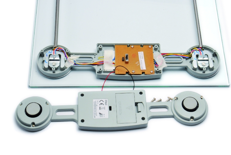
Hacking the Velleman scale
Our system is designed to be matched to the high-capacity scale produced by Velleman. But you can using any scale usign 4 load cells. The original Velleman electronics and display must be phased out and replaced with our project.
The scale structure is made up of 4 load cells (arranged on the 4 corners), which are configured between them so as to create a single Wheatstone bridge.
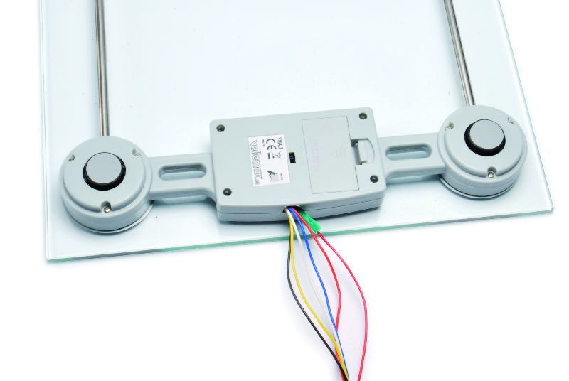
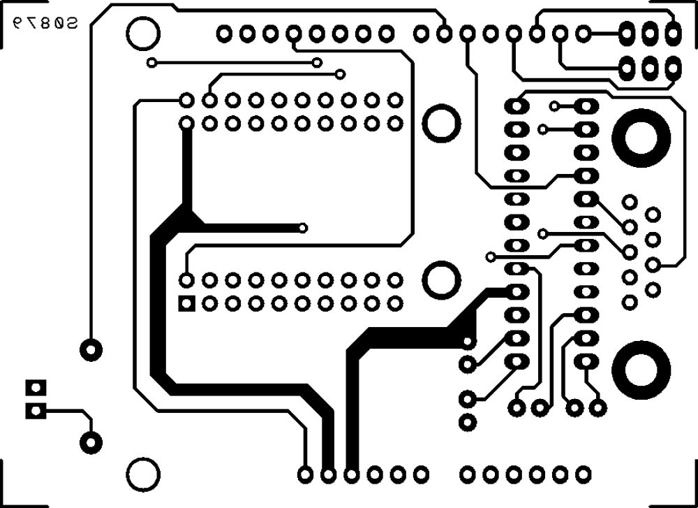
To make the connection to our board you must disassemble the lower section of the scale in order to access the electronics.
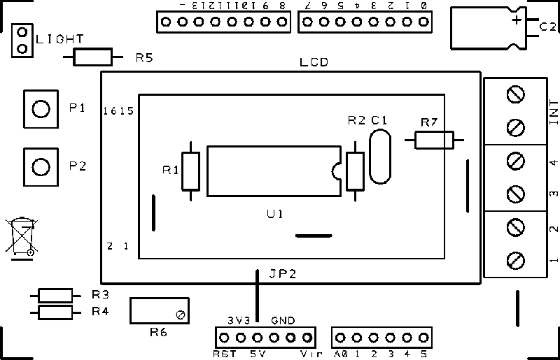
Referring to Fig A, which shows the structure of the scale viewed from below, with a quick visual analysis is easy to figure out that some blue and red wires are connected to each other while the yellow wires are connected to the switches positioned on the front of the two cells that identify the presence of a person.
To hack the scale follow these steps:
-
unsolder or cut all the red and blue wires, push in short those that were already shorted previously,
-
unsolder or cut the yellow wires coming from the cells numbered 1 and 3, put them in parallel (possibly by welding), extend them and take them to the two terminals on the new INT printed board (Fig.B)
-
unsolder or cut the white wire that is referred to as G3 (Wheatstone bridge mass) on the original printed circuit, extend take it to terminal 1 on the new printed circuit;
-
unsolder or cut the white wire that is referred to as G2 (Wheatstone bridge positive) on the original printed circuit, extend take it to terminal 3 on the new printed circuit;
-
unsolder or cut the white wire that is referred to as G1 and G4 on the original printed circuit, extend take it to terminal 4 and 2 on the new printed circuit (differential signal on the Wheatstone bridge)

The Sketch

As for the LCD, Arduino provides a convenient library (<LiquidCrystal.h>) already supporting different kinds of LCD (both 8 and 16 chars for 2 lines) based on the parallel interface chipset HD44780.
After the inclusion of the library, you must initialize the connection to the display, through LiquidCrystal LCDDisplay (8, A0, 3, 5, 6, 7), in this command, the parameters passed to the function and indicate Arduino’s hardware pins used to connect RS, Enable, D4, D5, D6 and D7 pins of the display.
Depending on the Arduino setup could be necessary to execute LCDDisplay.begin (width, height) in which the parameters indicate the physical dimensions of the display: LCDDisplay.begin (8, 2) in this case.
The library makes available instructions:
- LCDDisplay.setCursor (x, y) to position the cursor in a certain position
-
LCDDisplay.print (String) to print strings
Management of Arduino’s EEPROM is done by the <EEPROM.h> library that, once included, provides the functions:
-
EEPROM.write (add, date) to write a byte in a particular cell and
-
EEPROM.read (add) that the instead reads a byte from one cell (the add parameter specifies the address of the EEPROM cell).
Wi-Fi network and internet connection are managed thanks to the <WiServer.h> library; you just need to define some variables to configure the network (like IP’s and Network masks).
The adapter to connect and publish data on Google Documents shall operate as a Web Client: this configuration is done in the setup instruction WiServer.init (NULL) in which the NULL parameter specifies client mode.
You must create a function that will receive and handle the response from the server, this is done by the googlePublish.setReturnFunc (Gestione_Risposte_Web) instruction in our example. This function must be defined later in the code: in our example is void Gestione_Risposte_Web (char * data, int len) and receives as parameters both a pointer to a string containing the response and the length (in bytes) of the response.
Sending information requires to make a POST request to Google’s servers: WiServer library makes available a POSTrequest just to do this.
You must define the IP address of the server to which you want to connect (Google in our case) and define a structure of the POSTrequest (in our case, the variable is called googlePublish) containing the IP address of the server, the TCP / IP port the server name (spreadsheets.google.com), URL of POST execution and finally a function (SearchQuery in our case) that builds POST request body.
/******************************************************
 BilanciaWiFi
 Autori: Ingg. Tommaso Giusto e Ing. Alessandro Giusto
 Email:  tommro@libero.it
******************************************************/

// Inclusione Libreria per Display LCD 8x2
#include <LiquidCrystal.h>
// Inclusione Libreria per EEPROM scheda
#include <EEPROM.h>
// Inclusione Libreria per Server Web WiFi
#include <WiServer.h>
// Inclusione Libreria per SD Card
//#include <SD.h>

// Definizione pin INPUT/OUTPUT
const int PinVPeso = A1;         // Ingresso analogico uscita peso
const int PinPulsanteP1 = A3;    // Ingresso pulsante P1 su A3
const int PinPulsanteP2 = A4;    // Ingresso pulsante P2 su A4
const int PinInterruttore = A5;  // Ingresso interruttore su A5

// Definizione/Inizializzazione PIN Display LCD
// LCD RS pin D8
// LCD Enable on pin A0
// LCD D4, D5, D6, D7 on pins D3, D5, D6, D7
// LCD R/W pin a massa
// LCD V0 pin trimmer tra +5V e massa
LiquidCrystal LCDDisplay (8, A0, 3, 5, 6, 7);

/******************************************************
 Definizione struttura EEPROM
******************************************************/

/*****************************************************/
// Byte 0x000        Nome
// ...               Utente
// Byte 0x01F        000 (0x00 Carattere fine stringa)
// ...
// ...
// ...
// Byte 0x120        Nome
// ...               Utente
// Byte 0x13F        009 (0x00 Carattere fine stringa)
/*****************************************************/
#define StartNomiUtentiEEPROMADD          0x0000
#define EndNomiUtentiEEPROMADD            0x013F
#define DimensioneNomeUtenteEEPROMADD     32
#define NumMaxNomiUtenti                  10

/*****************************************************/
// Byte 0x140        Parte Alta Peso Utente 000
// Byte 0x141        Parte Bassa Peso Utente 000
// ...
// ...
// ...
// Byte 0x152        Parte Alta Peso Utente 009
// Byte 0x153        Parte Bassa Peso Utente 009
/*****************************************************/
#define StartPesiUtentiEEPROMADD          0x0140
#define EndPesiUtentiEEPROMADD            0x0153
#define DimensionePesoUtenteEEPROMADD     2

#define PesoMIN                           100
#define PesoMAX                           2000
#define AnalogDifferenzaPesoMAX           15

#define CalibrazioneSensoreMIN            0
#define CalibrazioneSensoreMAX            80

/******************************************************
 Definizione variabili globali
******************************************************/

// Definizione Parametri Rete Wireless
#define WIRELESS_MODE_INFRA	1  // Infrastrutturata (basata su Access Point)
#define WIRELESS_MODE_ADHOC	2  // Ad-hoc (senza Access Point)

// Parametri di rete
unsigned char local_ip[] = {192, 168, 0, 89};      // Indirizzo IP
unsigned char gateway_ip[] = {192, 168, 0, 254};	    // Indirizzo gateway IP
unsigned char subnet_mask[] = {255, 255, 255, 0};   // Subnet Mask
const prog_char ssid[] PROGMEM = {"FlashMob"};	    // SSID access point

// Selezione tipo di cifratura rete Wireless
unsigned char security_type = 0;  // 0 -> nessuna cifratura
                                  // 1 -> cifratura WEP
                                  // 2 -> cifratura WPA
                                  // 3 -> cifratura WPA2

// Password cifratura per WPA/WPA2 (max. 64 cratteri)
const prog_char security_passphrase[] PROGMEM = {"12345678"};

// Password cifratura per WEP 128-bit keys
prog_uchar wep_keys[] PROGMEM = {0x01, 0x02, 0x03, 0x04, 0x05, 0x06, 0x07, 0x08, 0x00, 0x00, 0x00, 0x00, 0x00,
				 0x00, 0x00, 0x00, 0x00, 0x00, 0x00, 0x00, 0x00, 0x00, 0x00, 0x00, 0x00, 0x00,
				 0x00, 0x00, 0x00, 0x00, 0x00, 0x00, 0x00, 0x00, 0x00, 0x00, 0x00, 0x00, 0x00,
				 0x00, 0x00, 0x00, 0x00, 0x00, 0x00, 0x00, 0x00, 0x00, 0x00, 0x00, 0x00, 0x00};

// Selezione tipo di rete Wireless infrastrutturata
unsigned char wireless_mode = WIRELESS_MODE_INFRA;

// Variabili per lunghezza SSID e password di cifratura
unsigned char ssid_len;
unsigned char security_passphrase_len;

// Definizione Parametri Pubblicazione Google
// Indirizzo IP per server www.google.it
uint8 google_ip[] = {209, 85, 229, 101};

// Richiesta POST verso GOOGLE
POSTrequest googlePublish (google_ip, 80, "spreadsheets.google.com", "", searchQuery);

// Stringa per eseguire pubblicazione
char newURL[] = {"/formResponse?formkey=dDFPcWhxNlZxMEpnUnhNdE5fT1lDcWc6MQ&ifq&entry.0.single=++++++++++++++++++++++++++++++++&entry.1.single=999,9&submit=Submit"};

// This function generates the body of our POST request
void searchQuery() {
}

// Indica presenza SD Card
//boolean presenzaSDCard;

// Inizializzazione Scheda
void setup() {
  // Inizializzo dimensioni LCD (8x2)
  LCDDisplay.begin (8, 2);

  // Inizializzo pin usati come INPUT/OUTPUT
  pinMode (PinInterruttore, INPUT);
  pinMode (PinPulsanteP1, INPUT);
  pinMode (PinPulsanteP2, INPUT);

  // Se all'accensione rilevati tutti e 2 i pulsanti premuti
  if ((PulsantePremuto (PinPulsanteP1) == 1) &&
      (PulsantePremuto (PinPulsanteP2) == 1)) {
    // Segnalo inizializzazione in corso
    LCDDisplay.setCursor (0, 0);
    LCDDisplay.print ("Init EEP");
    LCDDisplay.setCursor (0, 1);
    LCDDisplay.print ("in corso");

    // Inizializzo EEPROM scheda
    InizializzaEEPROM();
    // Attesa
    delay (500);
  }
  // Inizializzo porta seriale
  Serial.begin (9600);
  Serial.println ("Bilancia WiFi");
  Serial.println ("By Ingg. Tommaso e Alessandro Giusto");
  // Invio stato utenti
  InviaProgrammazioneUtenti();

  // Segnalo Avvio Web
  LCDDisplay.setCursor (0, 0);
  LCDDisplay.print ("  Init  ");
  LCDDisplay.setCursor (0, 1);
  LCDDisplay.print ("  web   ");

  // Inizializzo WiServer
  WiServer.init (NULL);
  WiServer.enableVerboseMode (false);

  // Inizializzazione richiesta POST (parametro indica funzione a cui verra' passata la risposta)
  googlePublish.setReturnFunc (Gestione_Risposte_Web);

/*
  // Inizializzo SD Card
  pinMode(10, OUTPUT);
  presenzaSDCard = SD.begin (4);
  // Se inizializzazione SD fallita
  if (presenzaSDCard == false)
    Serial.println ("Init SD FAULT!");
  // Se inizializzazione SD riuscita
  else
    Serial.println ("Init SD OK!");
*/
}

// Programma Principale
void loop() {
  // Ciclo infinito di esecuzione
  for (;;) {
    // Gestione Peso
    GestionePeso();

    // Per circa 1 sec
    for (byte tmp = 0; tmp < 250; tmp++) {
      // Gestione programmazione seriale
      GestioneSeriale();
      // Gestione WiServer
      GestioneWiServer();
      // Attesa
      delay (4);
    }    // Chiusura ciclo for per circa 1 sec
  }    // Chiusura ciclo infinito di esecuzione
}

/******************************************************
 Definizione funzioni
******************************************************/

// Funzione Gestione Peso
void GestionePeso() {
  // Indice utente selezionato
  //    0,..,(NumMaxNomiUtenti-1) -> selezionato utente 1,..,NumMaxNomiUtenti
  //    0xFF -> nessun utente selezionato
  static int IndiceUtenteSelezionato = 0xFF;
  // Indica l'indice carattere visualizzato
  static int IndiceCarattere = 0;
  String NomeUtenteSelezionato;
  int PesoUtenteSelezionato;
  int LunghezzaNomeUtenteSelezionato;
  int ValoreSensorePeso1, ValoreSensorePeso2;
  int ValoreSensorePesoTMP1, ValoreSensorePesoTMP2, ValoreSensorePesoTMP3, ValoreSensorePesoTMP4;
  static int CalibrazioneSensore;
  int CalibrazioneSensoreTMP;
  int PesoCalcolato;
  int tmp;

  // Se non premuto interruttore (utente non salito)
  if (PulsantePremuto (PinInterruttore) == 0) {
    // Leggo valore sensore per calibrazione
    CalibrazioneSensoreTMP = analogRead (PinVPeso);
    // Se valore sensore per calibrazione valido
    if ((CalibrazioneSensoreTMP >= (int) (CalibrazioneSensoreMIN)) &&
      (CalibrazioneSensoreTMP <= (int) (CalibrazioneSensoreMAX)))
      // Aggiorno valore sensore per calibrazione
      CalibrazioneSensore = CalibrazioneSensoreTMP;
  }    // Chiusura if non premuto interruttore (utente non salito)

  // Se premuto tasto 1
  if (PulsantePremuto (PinPulsanteP1) == 1) {
    // Azzero indice carattere visualizzato
    IndiceCarattere = 0;

    // Verifico tutte le posizioni utente
    for (tmp = 0; tmp < NumMaxNomiUtenti; tmp++) {
      // Seleziono utente selezionato
      switch (IndiceUtenteSelezionato) {
        // Se selezionato ultimo utente/nessun utente selezionato
        case (NumMaxNomiUtenti - 1): case 0xFF:
          // Seleziono primo utente
          IndiceUtenteSelezionato = 0;
          break;    // Chiusura case selezionato ultimo utente/nessun utente selezionato

        // Se selezionato altro utente
        default:
          // Seleziono prossimo utente
          IndiceUtenteSelezionato++;
          break;    // Chiusura case nessun utente selezionato
      }    // Chiusura switch seleziono utente selezionato

      // Se trovato utente con nome non nullo
      if (LeggiNomeUtente (IndiceUtenteSelezionato).length() != 0x00)
        // Blocco ciclo for verifico tutte le posizioni utente
        break;
    }    // Chiusura ciclo for verifico tutte le posizioni utente

    // Se non trovato utente con nome non nullo
    if (tmp == NumMaxNomiUtenti)
      // Seleziono nessun utente
      IndiceUtenteSelezionato = 0xFF;
  }    // Chiusura if premuto tasto 1

  // Se utente selezionato
  if (IndiceUtenteSelezionato != 0xFF) {
    // Leggo nome/peso utente
    NomeUtenteSelezionato = LeggiNomeUtente (IndiceUtenteSelezionato);
    PesoUtenteSelezionato = LeggiPesoUtente (IndiceUtenteSelezionato);
    // Calcolo lunghezza nome utente
    LunghezzaNomeUtenteSelezionato = NomeUtenteSelezionato.length();
    // Seleziono lunghezza nome utente
    switch (LunghezzaNomeUtenteSelezionato) {
      case 0:
        // Indico nessun utente selezionato
        IndiceUtenteSelezionato = 0xFF;
        break;
      case 1: case 2: case 3: case 4: case 5: case 6: case 7:
        LCDDisplay.clear();
        LCDDisplay.setCursor ((8 - LunghezzaNomeUtenteSelezionato) / 2, 0);
        LCDDisplay.print (NomeUtenteSelezionato);
        break;
      case 8:
        LCDDisplay.setCursor (0, 0);
        LCDDisplay.print (NomeUtenteSelezionato);
        break;
      default:
        if ((IndiceCarattere + 8) > LunghezzaNomeUtenteSelezionato)
          IndiceCarattere = 0;

        LCDDisplay.setCursor (0, 0);
        LCDDisplay.print (&NomeUtenteSelezionato[IndiceCarattere]);

        // Messaggio scorrevole
        IndiceCarattere++;
        if ((IndiceCarattere + 8) > LunghezzaNomeUtenteSelezionato)
          IndiceCarattere = 0;
        break;
    }    // Chiusura switch seleziono lunghezza nome utente
    LCDDisplay.setCursor (0, 1);
    LCDDisplay.print (PesoUtenteSelezionato / 1000);
    LCDDisplay.print ((PesoUtenteSelezionato % 1000) / 100);
    LCDDisplay.print ((PesoUtenteSelezionato % 100) / 10);
    LCDDisplay.print (".");
    LCDDisplay.print (PesoUtenteSelezionato % 10);
    LCDDisplay.print (" Kg");

    // Se premuto interruttore (utente salito)
    if (PulsantePremuto (PinInterruttore) == 1) {
      LCDDisplay.setCursor (0, 1);
      LCDDisplay.print ("..... Kg");

      // Leggo valore analogico peso
      for (;;) {
        // Attesa
        delay (500);
        // Eseguo prima lettura peso
        ValoreSensorePesoTMP1 = analogRead (PinVPeso);
        delay (125);
        ValoreSensorePesoTMP2 = analogRead (PinVPeso);
        delay (125);
        ValoreSensorePesoTMP3 = analogRead (PinVPeso);
        delay (125);
        ValoreSensorePesoTMP4 = analogRead (PinVPeso);
        delay (125);
        ValoreSensorePeso1 = ((ValoreSensorePesoTMP1 + ValoreSensorePesoTMP2 + ValoreSensorePesoTMP3 + ValoreSensorePesoTMP4) / 4);

        // Attesa
        delay (500);
        // Eseguo seconda lettura peso
        ValoreSensorePesoTMP1 = analogRead (PinVPeso);
        delay (125);
        ValoreSensorePesoTMP2 = analogRead (PinVPeso);
        delay (125);
        ValoreSensorePesoTMP3 = analogRead (PinVPeso);
        delay (125);
        ValoreSensorePesoTMP4 = analogRead (PinVPeso);
        delay (125);
        ValoreSensorePeso2 = ((ValoreSensorePesoTMP1 + ValoreSensorePesoTMP2 + ValoreSensorePesoTMP3 + ValoreSensorePesoTMP4) / 4);

        // Se peso stabilizzato
        if ((ValoreSensorePeso1 <= ValoreSensorePeso2) && ((ValoreSensorePeso2 - ValoreSensorePeso1) < (int) (AnalogDifferenzaPesoMAX)) ||
            (ValoreSensorePeso1 > ValoreSensorePeso2) && ((ValoreSensorePeso1 - ValoreSensorePeso2) < (int) (AnalogDifferenzaPesoMAX)))
          // Blocco ciclo for leggo valore analogico peso
          break;
      }    // Chiusura ciclo for leggo valore analogico peso

      // Calcolo peso utente
      PesoCalcolato = (int) (ValoreSensorePeso2 - CalibrazioneSensore);
      PesoCalcolato = (PesoCalcolato + (((int) (PesoCalcolato * (int) (10))) / (int) (62)));

//    68.1 KG
//    642   con calibrazione: 62 -> Veff = 580

      // Se peso valido
      if ((PesoCalcolato >= (int) (PesoMIN)) && (PesoCalcolato <= (int) (PesoMAX))) {
        // Memorizzo peso utente
        ScriviPesoUtente (IndiceUtenteSelezionato, PesoCalcolato);

        // Visualizzo peso calcolato
        LCDDisplay.setCursor (0, 1);
        LCDDisplay.print (PesoCalcolato / 1000);
        LCDDisplay.print ((PesoCalcolato % 1000) / 100);
        LCDDisplay.print ((PesoCalcolato % 100) / 10);
        LCDDisplay.print (".");
        LCDDisplay.print (PesoCalcolato % 10);
        LCDDisplay.print (" Kg");

        // Richiedo pubblicazione
        LCDDisplay.setCursor (0, 0);
        LCDDisplay.print ("Pubblic?");

        // Per massimo 5 secondi attendo pressione tasto 2
        for (tmp = 0; tmp < 10; tmp++) {
          // Se premuto tasto 2
          if (PulsantePremuto (PinPulsanteP2) == 1) {
            // Indico pubblicazione in corso
            LCDDisplay.setCursor (0, 0);
            LCDDisplay.print ("Pubblic.");
            LCDDisplay.setCursor (0, 1);
            LCDDisplay.print ("  wait  ");

            // Eseguo pubblicazione
            for (tmp = 0; tmp < NomeUtenteSelezionato.length(); tmp++) {
              newURL[76 + tmp] = NomeUtenteSelezionato.charAt(tmp);
              if (newURL[76 + tmp] == ' ')
                newURL[76 + tmp] = '+';
            }
            newURL[124] = ((PesoCalcolato / 1000) + 0x30);
            newURL[125] = (((PesoCalcolato % 1000) / 100) + 0x30);
            newURL[126] = (((PesoCalcolato % 100) / 10) + 0x30);
            newURL[128] = ((PesoCalcolato % 10) + 0x30);
            googlePublish.setURL(newURL);
            googlePublish.submit();
            delay (500);
            // Blocco ciclo for
            break;
          }
          delay (500);
        }    // Chiusura ciclo for per massimo 5 secondi attendo pressione tasto 2
/*
        // Se SD rilevata
        if (presenzaSDCard == true) {
          // Verifico/Creo directory BilanciaWiFi
          if (!(SD.exists ("BilanciaWiFi")))
            SD.mkdir ("BilanciaWiFi");

          // Memorizzo il peso su file
          File filePeso;
          // Apro il file in scrittura
          char nomeFilePeso[50] = {"BilanciaWiFi/"};
          for (tmp = 0; tmp < NomeUtenteSelezionato.length(); tmp++) {
            charTmp[0] = NomeUtenteSelezionato.charAt(tmp);
            strcat (nomeFilePeso, charTmp);
          }
          strcat (nomeFilePeso, ".txt");
          filePeso = SD.open (nomeFilePeso, FILE_WRITE);

          // Se apertura file OK
          if (filePeso) {
            // Memorizzo il peso
            filePeso.print ((PesoCalcolato / 1000) + 0x30);
            filePeso.print (((PesoCalcolato % 1000) / 100) + 0x30);
            filePeso.print (((PesoCalcolato % 100) / 10) + 0x30);
            filePeso.print (".");
            filePeso.print ((PesoCalcolato % 10) + 0x30);
            filePeso.print (" Kg");
            // Chiudo il file:
            filePeso.close();
          }
        }
*/

        LCDDisplay.setCursor (0, 0);
        LCDDisplay.print ("  Step  ");
        LCDDisplay.setCursor (0, 1);
        LCDDisplay.print ("  off   ");

        // Attendo utente scende dalla bilancia
        for (;;) {
          // Se non premuto interruttore (utente non salito)
          if (PulsantePremuto (PinInterruttore) == 0)
            break;
        }
      }    // Chiusura if peso valido
    }    // Chiusura if premuto interruttore (utente salito)
  }    // Chiusura if utente selezionato

  // Se nessun utente selezionato
  else {
    LCDDisplay.setCursor (0, 0);
    LCDDisplay.print (" Chose  ");
    LCDDisplay.setCursor (0, 1);
    LCDDisplay.print (" user   ");
  }    // Chiusura if nessun utente selezionato
}

// Funzione Gestione Seriale
void GestioneSeriale() {
  String comandoRicevutoString = "";
  int numeroUtenteRicevuto;
  String nomeUtenteRicevuto = "";

  // Se ricevuti dati dalla porta seriale
  if (Serial.available()) {
    // Attendo tutti i dati
    delay (250);

    // Ricevo i dati
    while (Serial.available())
      comandoRicevutoString += (char) (Serial.read());

    // Invio comando ricevuto
    Serial.println (comandoRicevutoString);

    // Se ricevuti almeno 15 caratteri
    if (comandoRicevutoString.length() >= 15) {
      // Se ricevuto comando programmazione nome utente (NOME_UTENTE_xx=)USER_NAME_01=Boris
      if ((comandoRicevutoString.substring (0, 12).equals("P_USER_NAME_")) &&
          (isdigit(comandoRicevutoString.charAt (12))) &&
          (isdigit(comandoRicevutoString.charAt (13)))) {
        // Estraggo numero utente ricevuto
        numeroUtenteRicevuto = (((comandoRicevutoString.charAt (12) - 0x30) * 10) +
                                (comandoRicevutoString.charAt (13) - 0x30));
        // Se ricevuto numero utente corretto
        if ((numeroUtenteRicevuto >= 1) && (numeroUtenteRicevuto <= NumMaxNomiUtenti)) {
          // Estraggo nome utente
          nomeUtenteRicevuto = comandoRicevutoString.substring (15);
          // Se nome troppo lungo
          if (nomeUtenteRicevuto.length() > DimensioneNomeUtenteEEPROMADD)
            // Tronco il nome
            nomeUtenteRicevuto = nomeUtenteRicevuto.substring (0, DimensioneNomeUtenteEEPROMADD);

          // Memorizzo il nome
          ScriviNomeUtente (numeroUtenteRicevuto - 1, nomeUtenteRicevuto);
          // Azzero il relativo peso
          AzzeraPesoUtente (numeroUtenteRicevuto - 1);
          // Indico OK
          Serial.println ("OK");
          // Invio su  porta seriale lo stato utenti
          InviaProgrammazioneUtenti();
          // Termino funzione
          return;
        }
      }
    }

    // Indico errore
    Serial.println ("FAULT");
    // Termino funzione
    return;
  }
}

// Invia su  porta seriale lo stato utenti
void InviaProgrammazioneUtenti() {
  for (int numeroUtente = 0; numeroUtente < NumMaxNomiUtenti; numeroUtente++) {
    Serial.print ("Us. ");
    Serial.print ((numeroUtente + 1) / 10);
    Serial.print ((numeroUtente + 1) % 10);
    Serial.print (": ");
    Serial.println (LeggiNomeUtente (numeroUtente));
  }
}

// Funzione Gestione WiServer
void GestioneWiServer() {
  // Gestione WiServer
  WiServer.server_task();
}

// Gestione diverse risposte provenienti dal WEB
void Gestione_Risposte_Web (char* data, int len) {

  // Print the data returned by the server
  // Note that the data is not null-terminated, may be broken up into smaller packets, and
  // includes the HTTP header.
  while (len-- > 0) {
    Serial.print(*(data++));
  }

}

// Scrive il nome di un utente
// INPUT:   Posizione utente (0,..,9)
//          Nome utente in formato stringa
// OUTPUT:  -
// Note:    -
void ScriviNomeUtente (int NomePosition, String NomeUtente) {
  // Azzero nome utente selezionato
  AzzeraNomeUtente (NomePosition);

  // Scrivo i caratteri nome utente selezionato
  for (int tmp = 0; tmp < NomeUtente.length(); tmp++)
    EEPROM.write (StartNomiUtentiEEPROMADD + tmp +
                  (NomePosition * DimensioneNomeUtenteEEPROMADD), NomeUtente.charAt(tmp));
}

// Legge il nome di un utente
// INPUT:   Posizione utente (0,..,9)
// OUTPUT:  Nome utente in formato stringa
// Note:    -
String LeggiNomeUtente (int NomePosition) {
  String NomeUtente = "";
  char NomeUtenteChar;

  // Leggo i caratteri nome utente selezionato
  for (int tmp = 0; tmp < DimensioneNomeUtenteEEPROMADD; tmp++) {
    // Leggo singolo carattere
    NomeUtenteChar = EEPROM.read (StartNomiUtentiEEPROMADD + tmp +
                                  (NomePosition * DimensioneNomeUtenteEEPROMADD));

    // Se trovato carattere fine nome
    if (NomeUtenteChar == 0x00)
      // Blocco ciclo for leggo i caratteri nome utente selezionato
      break;

    // Accodo carattere letto
    NomeUtente = NomeUtente + NomeUtenteChar;
  }

  // Ritorno il nome
  return (NomeUtente);
}

// Azzera il nome di un utente
// INPUT:   Posizione utente (0,..,9)
// OUTPUT:  -
// Note:    -
void AzzeraNomeUtente (int NomePosition) {
  // Azzero caratteri nome utente selezionato
  for (int tmp = 0; tmp < DimensioneNomeUtenteEEPROMADD; tmp++)
    EEPROM.write (StartNomiUtentiEEPROMADD + tmp +
                  (NomePosition * DimensioneNomeUtenteEEPROMADD), 0);
}

// Scrive il peso di un utente
// INPUT:   Posizione utente (0,..,9)
//          Peso utente
// OUTPUT:  -
// Note:    -
void ScriviPesoUtente (int PesoPosition, int PesoUtente) {
  // Memorizzo peso nome utente
  EEPROM.write (StartPesiUtentiEEPROMADD +
                (PesoPosition * DimensionePesoUtenteEEPROMADD), (byte) (PesoUtente >> 8));
  EEPROM.write (StartPesiUtentiEEPROMADD + 1 +
                (PesoPosition * DimensionePesoUtenteEEPROMADD), (byte) (PesoUtente & 0x00FF));
}

// Legge il peso di un utente
// INPUT:   Posizione utente (0,..,9)
// OUTPUT:  Peso utente
// Note:    -
int LeggiPesoUtente (int PesoPosition) {
  // Ritorno il peso
  return (((int) (EEPROM.read (StartPesiUtentiEEPROMADD +
                               (PesoPosition * DimensionePesoUtenteEEPROMADD))) << 8) +
           (int) (EEPROM.read (StartPesiUtentiEEPROMADD + 1 +
                               (PesoPosition * DimensionePesoUtenteEEPROMADD))));
}

// Azzera il peso di un utente
// INPUT:   Posizione utente (0,..,9)
// OUTPUT:  -
// Note:    -
void AzzeraPesoUtente (int PesoPosition) {
  // Azzero peso nome utente
  ScriviPesoUtente (PesoPosition, 0);
}

// Inizializza EEPROM scheda
// INPUT:   -
// OUTPUT:  -
// Note:    -
void InizializzaEEPROM() {
  // Azzero i nomi/pesi di tutti gli utenti
  for (int tmp = 0; tmp < NumMaxNomiUtenti; tmp++) {
    AzzeraNomeUtente (tmp);
    AzzeraPesoUtente (tmp);
  }
}

// Verifica lo stato di un pulsante
// INPUT:   Pin pulsante
// OUTPUT:  Stato pulsante    0 -> pulsante non premuto
//                            1 -> pulsante premuto
// Note:    -
int PulsantePremuto (int PinPulsante) {
  if (digitalRead (PinPulsante) == LOW)
    return (1);
  else
    return (0);
}
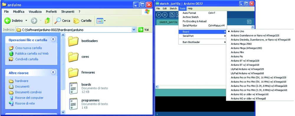
Install the WiShield libraries
To work properly, the Wifi shield requires specific libraries that must be installed in the Arduino IDE used to compile the sources so you’ll need to put these libraries in the Arduino libraries path.
The library supports multiple operating modes (APP_WEBSERVER, APP_WEBCLIENT, APP_SOCKAPP, APP_UDPAPP and APP_WISERVER).
The default value is APP_WEBSERVER, which runs on most Arduino systems but has several limitations. The main limitation is that it can’t function both as a client and server simultaneously.
It is therefore recommended the APP_WISERVER (in the library named “WiServer.h“) which allows the Arduino shield equipped with Wi-Fi to be configured and operated either as a Web Server as a Web Client.
In the first case, you can serve connection requests from external web clients and send HTML pages in response, in the second it will be possible to connect to a web server and send GET or POST requests.
To configure the WiShield library as APP_WISERVER you must open the apps-conf.h file, comment the “#define“ APP_WEBSERVER row and uncomment the “#define” of APP_WISERVER row.
Something like:
/ / # define APP_WEBSERVER
/ / # define APP_WEBCLIENT
/ / # define APP_SOCKAPP
/ / # define APP_UDPAPP
# defineAPP_WISERVER
Configuring publishing
Performing data publication on Google Documents requires three distinct steps:
- Configuring Wi-Fi network access;
- Creating a Google Docs form module: each module is characterized by an identifying 34 characters string – FormKey) and each field is characterized by an identification number (called Entry).
- Inserting the FormKey / Entry in the Arduino software.
Configuring network parameters
First you must configure and update the IP address, Subnet Mask, Gateway IP and Network SSID, then select the encryption mode and change password information for your network. Save all, compile and run the upload Software tab.
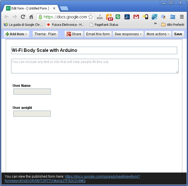
Creating the Google module doc

Create a form on Google Docs, modify the form with two fields (username and weight, both of type string) and save the job. (the result is something like the one shown in Figure). In our case, we left the default file name and called the two fields “User Name” and “User weight”
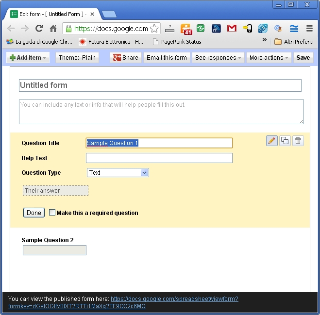
take note of this key string because then it will be inserted in the Arduino software: as you can see from the picture, the link shows the form key assigned to the module (in this example, the link is: https://docs.google.com/spreadsheet/viewform?formkey=dDFPcWhxNlZxMEpnUnhNdE5fT1lDcWc6MQ which implies that the form assigned key is “dDFPcWhxNlZxMEpnUnhNdE5fT1lDcWc6MQ”);
Clicking on the link will open a new page that shows the data entry form: within this form text fields are marked with “entry.0.single“, “entry.1.single“, etc … (basically with an integer id)
To see which number has been assigned to our fields you need to display the HTML source of the form (the result is something like the one shown in this Figure).
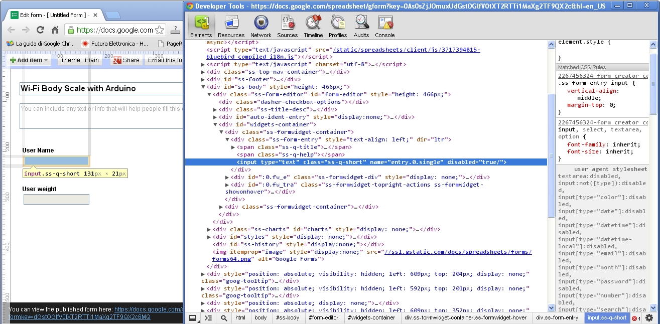
You can easily find the ID numbers assigned to different fields (in our example “entry.0.single” is the “Name” and “entry.1.single” is the “weight“).
Take note of this information because it will be included in the source Arduino as well.
Formkey / entry
Once you have created the form, the Arduino source will be configured so that it is compatible with the form you created.
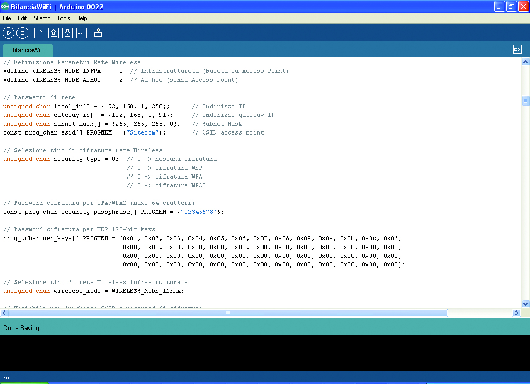
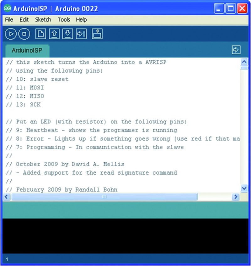
A variable is defined in Arduino source named newURL[]: the variable is initialized with a standard format then modified to perform publication (refer to Figure 11 to identify it in the code).
Replace the default values with those obtained at the time of the creation of the form, compile and download it to the Arduino board.

How to program user names
The configuration of user names can be made via serial port and Serial Monitor. To program it, connect to the board (via USB cable) and open the Arduino Serial Monitor. As a first step the card sends a summary of the current configuration.
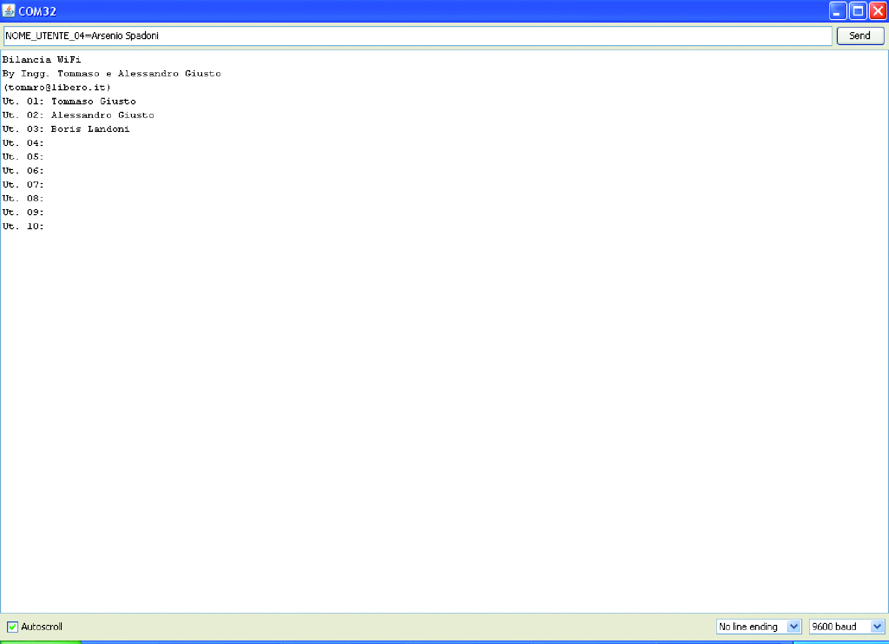
To program a new user name you must send a string in the format “P_USER_NAME_xx = User Name” with xx between 01 and 10 ID (put an empty string to delete the selected user.) If all the posted information is correct, this is confirmed by the message “Ok” otherwise “Fault”.
Using the scale
The scale software is able to distinguish up to 10 users (each identified by its name) and, for each one, it stores the last measured weight.
If you want to clear the memory (which we recommend at first use) is sufficient to hold down either of the two buttons (the display indicates the operation with “EEP init in progress”).
Later, you can configure names following the procedure described in the “Programming user names” section.
As the next step the Web management interface will start and the system will enter its normal operation. The user selection is done by pressing button P1.
Going over the scale starts the weighing procedure (lasting several seconds): weight is displayed and stored and the scale asks for publishing on the web: by pressing P2 the operation is performed.


