

Lighted plexiglass Christmas ornaments (Arduino version)

In the previous post we showed you how to make small Christmas shapes using an RGB LED and a small circuit based on PIC.
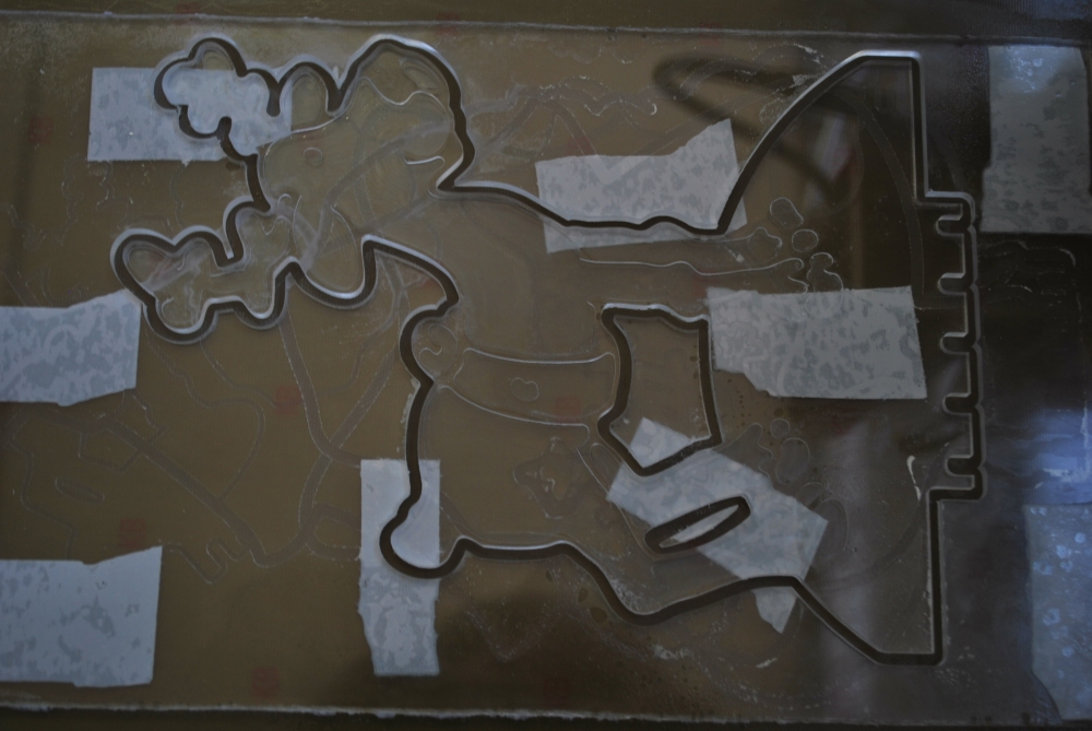
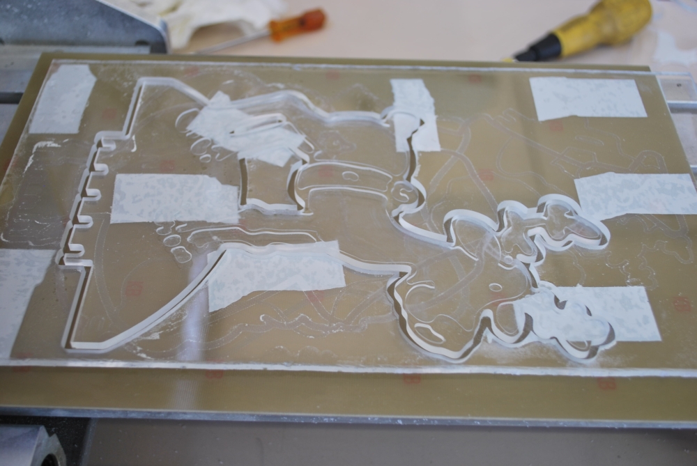
The designs were obtained working with the CNC some acrylic sheets.
But our CNC can do much more … Therefore we decided to make the greatest figure and design a new driver that mounts more LEDs.
Just because we do not like things simple ![]() we recreated all using a system based on Arduino.
we recreated all using a system based on Arduino.
This allows you to create an open source system easy to modify.
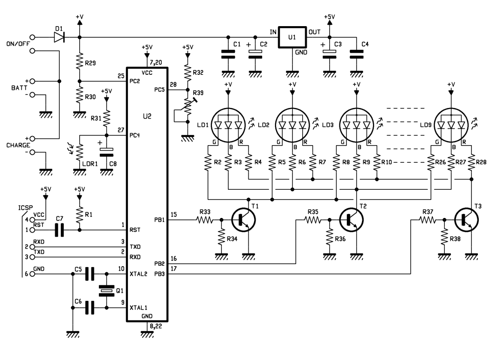
The microcontroller is an Atmega328 preprogrammed with the bootloader of Arduino UNO. The programming can be done via a USB / TTL (eg FTDI5V of SparkFun).
The circuit operation is very similar to that of the smallest model: here we find the photocell that allows to verify the amount of light present in the environment, but in this case, you can adjust the sensitivity of the circuit by a trimmer.
BOM
R1: 10 kohm
R2: 820 ohm
R3: 820 ohm
R4: 1 kohm
R5: 820 ohm
R6: 820 ohm
R7: 1 kohm
R8: 820 ohm
R9: 820 ohm
R10: 1 kohm
R11: 820 ohm
R12: 820 ohm
R13: 1 kohm
R14: 820 ohm
R15: 820 ohm
R16: 1 kohm
R17: 820 ohm
R18: 820 ohm
R19: 1 kohm
R20: 820 ohm
R21: 820 ohm
R22: 1 kohm
R23: 820 ohm
R24: 820 ohm
R25: 1 kohm
R26: 820 ohm
R27: 820 ohm
R28: 1 kohm
R29: 10 kohm
R30: 4,7 kohm
R31: 10 kohm
R32: 4,7 kohm
R33: 4,7 kohm
R34: 10 kohm
R35: 4,7 kohm
R36: 10 kohm
R37: 4,7 kohm
R38: 10 kohm
R39: Trimmer 4,7 kohm MV
C1: 100 nF
C2: 470 µF 25 VL
C3: 470 µF 25 VL
C4: 100 nF
C5: 15 pF
C6: 15 pF
C7: 100 nF
C8: 100 µF 25 VL
T1: BC547
T2: BC547
T3: BC547
LD1: LED 5 mm RGB c.a.
LD2: LED 5 mm RGB c.a.
LD3: LED 5 mm RGB c.a.
LD4: LED 5 mm RGB c.a.
LD5: LED 5 mm RGB c.a.
LD6: LED 5 mm RGB c.a.
LD7: LED 5 mm RGB c.a.
LD8: LED 5 mm RGB c.a.
LD9: LED 5 mm RGB c.a.
U1: 7805
U2: ATMEGA328P-PU (with bootloader)
Q1: 16 MHz
LDR1: photoresistor 2÷20 kohm
- Terminal 2 via (3 pz.)
- Socket 14+14
- Battery 12V/2A
- Strip male 6 via
- Plug
- Switch
 |
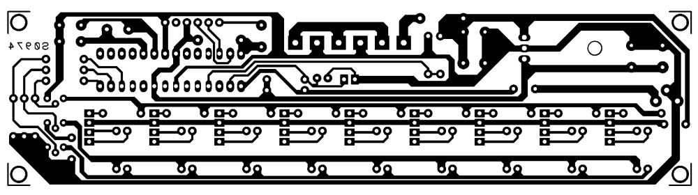 |
Comparing the value read from the A/D converter connected to the photoresistor with that connected to trimmer R39, the micro decides whether to start the sequence of fading, or whether turn off the LEDs. RGB LEDs are driven by the transistor; this choice permit to control with a single line of microcontroller, more LEDs in order to create large luminous figures.
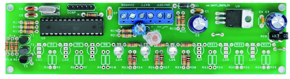
As you can see, we use a line dell’ATmega for each of the primary colors of red, green and blue, so it is clear that all the diodes will do the same play of light. Of course isn’t required to mount all the LEDs provided in the circuit: you mount those who need to obtain a good visual effect on the size of the pattern in the Plexiglass. Note that there are three terminals on the PCB: one to connect the power switch (ON / OFF) a second (BATT) to apply to the circuit power supply and a third (CHARGE) for a possible battery charger lead or a small 12-volt solar panel, which already incorporates the charging circuit. These solutions allow you to use the figures lack the power grid. In this regard, an analog input of the microcontroller is dedicated to control the battery voltage: when it drops below 10 V, the circuit will emit flashes to warn that the energy is about to end.

This circuit is evidently intended to be used externally (provided it is properly isolated) and will turn on and off independently, thanks to the ambient light sensor, which will illuminate the figures in the evening to let off in the morning. In short, is a solution to decorate the garden or backyard.
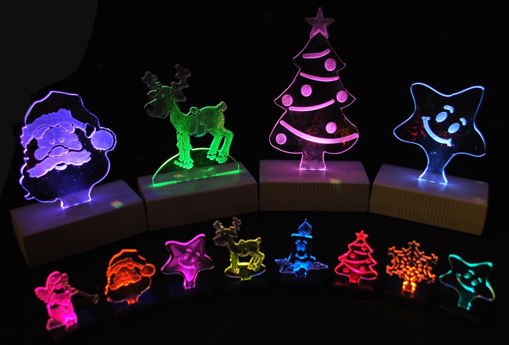

Building shapes
The materials chosen for this application are clear polycarbonate (or methacrylate) or Plexiglas, which can give the shape you want. Then we need to affect, deep enough (half or two thirds the thickness of the plate) the drawing or writing that you want to appear bright.
The Sketch
//****************************************************************
//*  Name    : RGB controller for common anode led               *
//*  Author  : Landoni Boris                                     *
//*  www.open-electronics.org                                    *
//*  blog.elettronicain.it                                       *
//*  www.futurashop.it                                           *
//****************************************************************

int red = 9;    // RED LED connected to PWM pin 3
int green = 10;    // GREEN LED connected to PWM pin 5
int blue = 11;    // BLUE LED connected to PWM pin 6
int photo = A4;    // BLUE LED connected to PWM pin 6
int trim = A5;    // BLUE LED connected to PWM pin 6
int volt = A2;    // BLUE LED connected to PWM pin 6
int r=50; int g=100; int b=150;
int rup; int gup; int bup;
int fader=1;
int inc=10;
void setup()
{
      Serial.begin(9600);
      Serial.println("Serial READY");
      rgb(r, g, b);
      r = random(0,255);
      g = random(0,255);
      b = random(0,255);

}

void loop()  {

  Serial.print("trim  ");
  Serial.println(analogRead(trim)*2);

  Serial.print("photo ");
  Serial.println(analogRead(photo));

  Serial.print("volt ");
  Serial.println(analogRead(volt));
  if (analogRead(volt)<600){
      Serial.println("low battery");
      rgb(0, 0, 0);
      delay(500);
      rgb(255, 255, 255);
  }

  if ((analogRead(trim)*2)>analogRead(photo)){
      Serial.println("trim > photo  -  off");
      rgb(0, 0, 0);
      fader=0;
  }
  else
  {
    if (fader==0){
      r = random(0,255);
      g = random(0,255);
      b = random(0,255);
    }
    fader=1;

  }
  //delay(2000);

  if (fader==1){
    funcfader();
  }
}

void funcfader(){
    Serial.println("fader");
    if (rup==1){r+=1;}
    else{r-=1;}
    if (r>=255){rup=0;}
    if (r<=0){rup=1;}

    if (gup==1){g+=1;}
    else{g-=1;}
    if (g>=255){gup=0;}
    if (g<=0){gup=1;}

    if (bup==1){b+=1;}
    else{b-=1;}
    if (b>=255){bup=0;}
    if (b<=0){bup=1;}

    delay(inc*2);
    rgb(r, g, b);
}

void rgb(int r, int g, int b)
{
  Serial.print("RGB: ");
  Serial.print(r);
  Serial.print(" ");
  Serial.print(g);
  Serial.print(" ");
  Serial.println(b);
  if (r>255) r=255;
  if (g>255) g=255;
  if (b>255) b=255;
  if (r<0) r=0;
  if (g<0) g=0;
  if (b<0) b=0;
  analogWrite(red, r);
  analogWrite(green, g);
  analogWrite(blue, b);
}
| Star | |
| Reindeer | |
| Santa Claus | |
| Tree |
[original story: Open Electronics]