Arduino DMX shield for Christmas projects
.
This shield allows to connect an Arduino with DMX equipment. It implements the RS485 interface to adapt the electrical levels needed for DMX connection.
This shield has been designed with flexibility in mind and allows the user to choose between several Arduino pins for digital input and output of DMX data, it supports a microSD slot and also has the serial connection to support a serial LCD display.
This design allows basic operation of DMX through simple pre programmed messages stored in the Arduino Sketch or, with the proper libraries and programming, it could well become a standalone system with playback capabilities of sequences stored on the microSD. When needed, this solution is also a suitable interface for a PC sending through a serial port the DMX commands.
DMX basics
This interfacing and communication standard has been developed to allow easier management of complex lighting systems. On stages and discos, many spots, pars, moving heads and other equipment need to be managed and controlled, but bringing power from a centralized panel rises many issues for safety and cabling complexity.
With DMX, each device has an integrated or external controller. A control system sends a specific message to each controller with a byte that the controller itself interprets according to its address and capabilities. Power supply becomes “local” and the communication is with a daisy chained cable that carries low voltage signals.
DMX data is sent in parallel to every controller connected and the address given to each controller allows each device to grab and interpret only the relevant information.
The transmission scheme has been designed for efficiency as DMX may drive up to 512 devices at the same time, with 40 complete transmission sets per second. To achieve this, with 8 bits, 1 start and 1 stop bit, speed has to be 250 kbps. The serial data starts with a header and then bytes are sent in sequence, starting from the first one.
If we have to send a new command to the controller with address 10, we need to send also the data relevant to the controllers from 1 to 9. The addressing system is based on position of the byte and each controller counts the incoming bytes, discarding the ones preceding and following its own byte.
It is also important to remember that each command received is always relevant, therefore to alter the state of a single controller, it is necessary to send valid commands to all the controllers that have a lower address. The sequence, however, may end when the address of the relevant controller has been reached (no need to send the sequence with data exceeding the relevant controller address).
The values from 0 to 255 initially represented the level of the light (0 = off, 255 = full brightness), but the adoption of DMX by other devices turned the meaning of the byte into other commands, eg. position, program selection, specific preset, activate feature and so on. Each manufacturer specifies the mapping between values and functions and sometimes a single byte is not enough to manage all the capabilities, therefore the device occupies an interval of addresses on the DMX bus and reads more than one byte, in sequence.
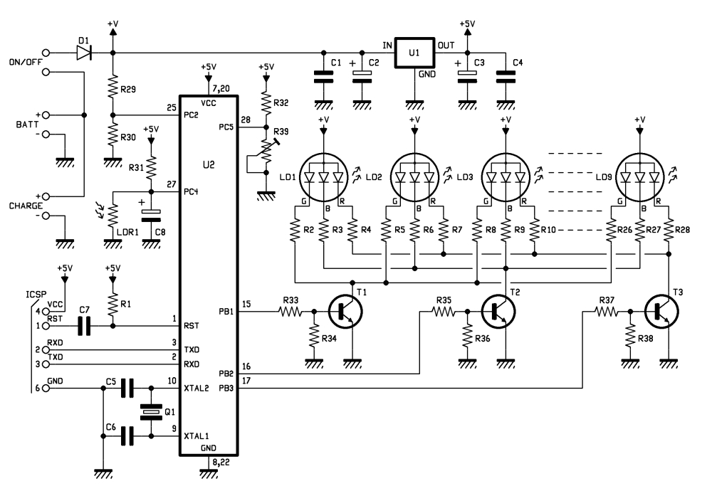
Shield schematics

This shield uses a MAX485 by Maxim to convert the signal levels from the Arduino digital pin to the RS485 differential simplex two wire plus ground connection. The MAX485 contains a receiver and a transmitter, with enabling signals. The /RE (pin 2) and OE (pin 3) – that enable reception and transmission – are with inverted levels, so that it is possible to use a single line and the two pins connected together to manage transmission direction. Pin 1 is Receive Output, pin 4 is Data Input, pin 6 and 7 are the differential outputs.

It is possible to choose between different Arduino D pins for each of the three signals needed: RO may be mapped onto D0 or D4, DI onto D1 or D3 and /RE+OE onto D2 or D5.
The other chip on the shield is an 74HC4050D that contains six buffers to match TTL levels from Arduino ICSP with the 3,3V required by the microSD. This is required just by microSD input lines because Arduino input correctly reads the 3,3V level supplied by microSD as a logic “1”.
The last bits of the schematics include a couple of LEDs connected to D7 and D8, a pushbutton on A1 and the serial connection for the LCD on A0/A2 (jumper selectable).
Configuration

Before you proceed with this shield, you should decide the various jumpers positions; if no other shield is used with Arduino, you are free to choose any of the two positions available; when used with other shields, use the jumpers to avoid any conflict. Please note that ICSP is used with Ethernet shields as well, therefore the microSD slot might create conflicts if used with an Ethernet equipped solution.
DMX library
DOWNLOAD DMX LIBRARY (Arduino1.0.1)
This shield needs a specific library named DmxSimple.h available for download at http://code.google.com/p/tinkerit/wiki/DmxSimple ; with it you will find some examples. We also have two other sketches to let you experiment with this shield.
/* Welcome to DmxSimple. This library allows you to control DMX stage and
** architectural lighting and visual effects easily from Arduino. DmxSimple
** is compatible with the Tinker.it! DMX shield and all known DIY Arduino
** DMX control circuits.
**
** DmxSimple is available from: http://code.google.com/p/tinkerit/
** Help and support: http://groups.google.com/group/dmxsimple       */

/* To use DmxSimple, you will need the following line. Arduino will
** auto-insert it if you select Sketch > Import Library > DmxSimple.

Modified by Boris Landoni
open-electronics.org

*/

#include

const int jrde =  2;
const int jdi  =  3;
const int jro  =  4;
const int lr   =  7;
const int ly   =  8;

void setup() {

  pinMode(jrde, OUTPUT);
  pinMode(jdi,  OUTPUT);
  pinMode(jro,  INPUT);
  pinMode(lr, OUTPUT);
  pinMode(ly, OUTPUT);

  digitalWrite(jrde, HIGH);

  /* The most common pin for DMX output is pin 3, which DmxSimple
  ** uses by default. If you need to change that, do it here. */
  DmxSimple.usePin(jdi);

  /* DMX devices typically need to receive a complete set of channels
  ** even if you only need to adjust the first channel. You can
  ** easily change the number of channels sent here. If you don't
  ** do this, DmxSimple will set the maximum channel number to the
  ** highest channel you DmxSimple.write() to. */
  DmxSimple.maxChannel(5);
}

void loop() {
  int brightness;
  /* Simple loop to ramp up brightness */
  for (brightness = 0; brightness <= 255; brightness++) {
    digitalWrite(lr, HIGH);
    /* Update DMX channel 1 to new brightness */
    //DmxSimple.write(1, brightness);
    DmxSimple.write(2, brightness);
    //DmxSimple.write(3, brightness);
    DmxSimple.write(4, 189);

    /* Small delay to slow down the ramping */
    delay(10);
    digitalWrite(lr, LOW);
  }

}
Vixen
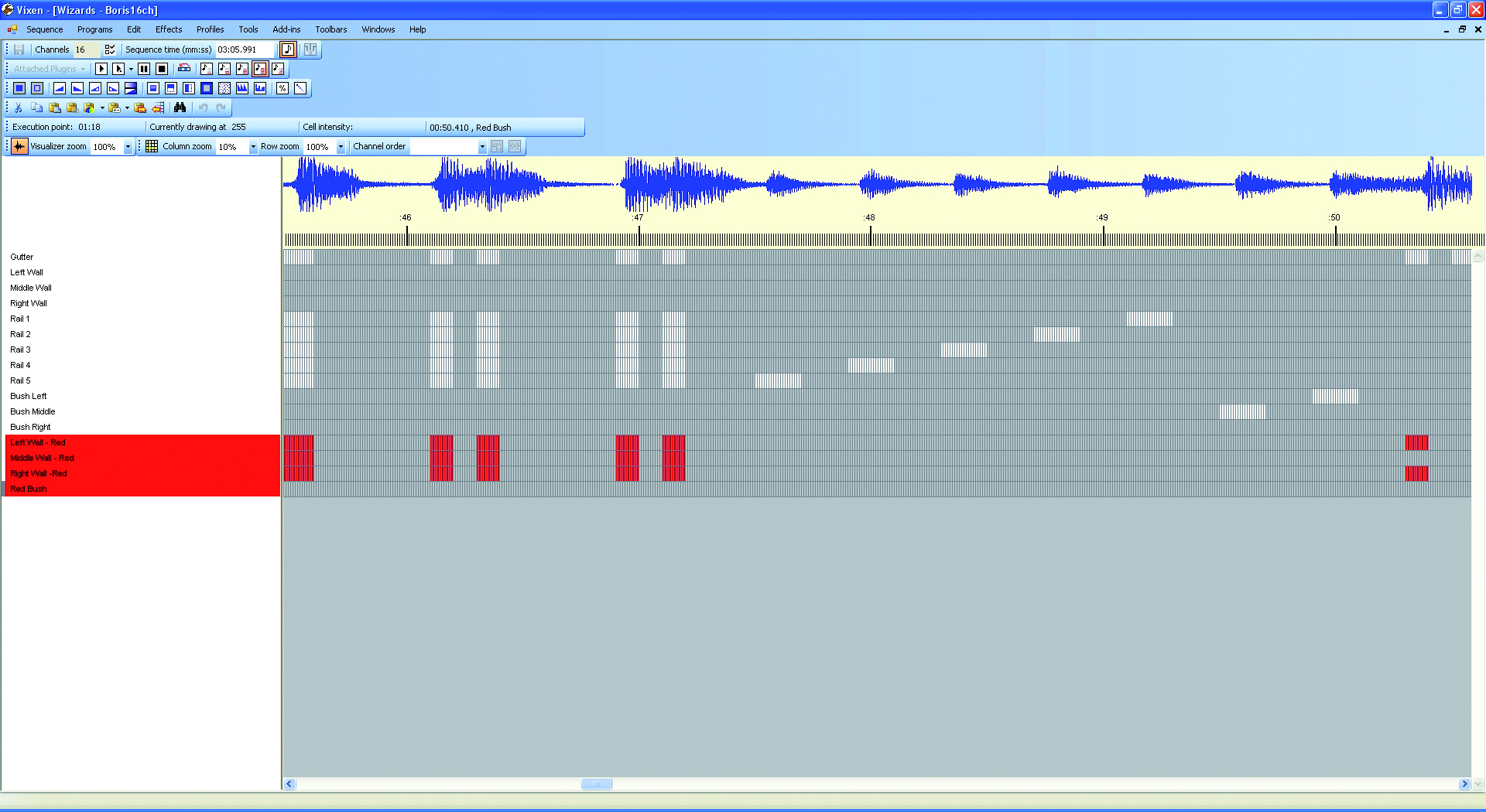
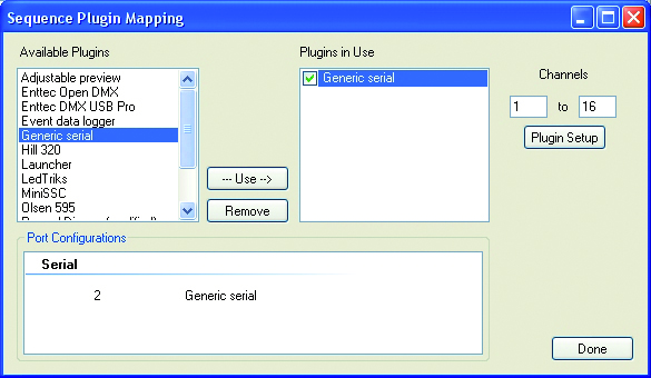
We also suggest to use Vixen (www.vixenlights.com) to create sequences on a PC, synced with music, that are sent to Arduino over the serial port. The communication between Arduino and Vixen is managed by our sketch DMX_LightSequencing.
/*
The purpose of this code is to allow the Arduino to use the
generic serial output of vixen lights to control 5 channels of LEDs.
Author: Matthew Strange
Created: 14 October 2010
Modifier: Ben Towner
Modified: 19-OCT-2010
Changes: Addition of 20 Digital On/Off Channels - Setup for Arduino Mega 2560
Modified by Boris Landoni
open-electronics.org

*/

#include

const int jrde =  2;
const int jdi  =  3;
const int jro  =  4;
const int lr   =  7;
const int ly   =  8;

#define DELAY    10

int i = 0;     // Loop counter
int incomingByte[25];   // array to store the 25 values from the serial port
int address=1;
int ch=16;
int k;

//setup the pins/ inputs & outputs
void setup()
{
  Serial.begin(9600);        // set up Serial at 9600 bps

  pinMode(jrde, OUTPUT);
  pinMode(jdi,  OUTPUT);
  pinMode(jro,  INPUT);
  pinMode(lr, OUTPUT);
  pinMode(ly, OUTPUT);

  digitalWrite(jrde, HIGH);

  /* The most common pin for DMX output is pin 3, which DmxSimple
  ** uses by default. If you need to change that, do it here. */
  DmxSimple.usePin(jdi);

  /* DMX devices typically need to receive a complete set of channels
  ** even if you only need to adjust the first channel. You can
  ** easily change the number of channels sent here. If you don't
  ** do this, DmxSimple will set the maximum channel number to the
  ** highest channel you DmxSimple.write() to. */
  DmxSimple.maxChannel(ch);

  for (k=0; k= ch) {
    // read the oldest byte in the serial buffer:
      for (k=0; k