Posts with «tidigino» label

Arduino Full Memory: upgrade to the last ATMEL Toolchain version

This short report is aimed to the most “advanced” users of Arduino boards, especially to the users of the “Mega” flavors of the family, but also users of standard versions of the board, like Arduino UNO and Arduino Duemilanove, can take advantage of the following notes.

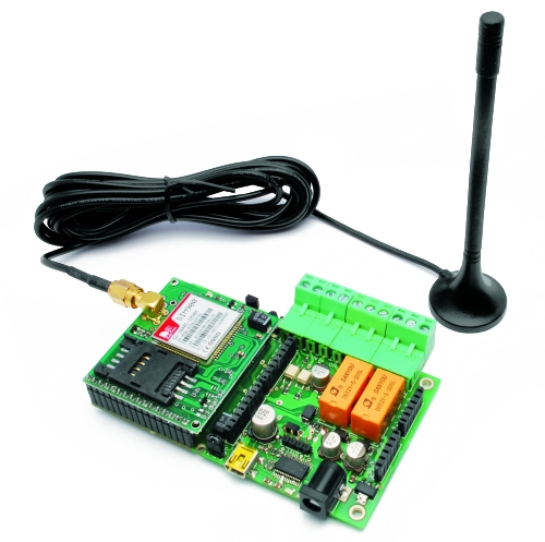
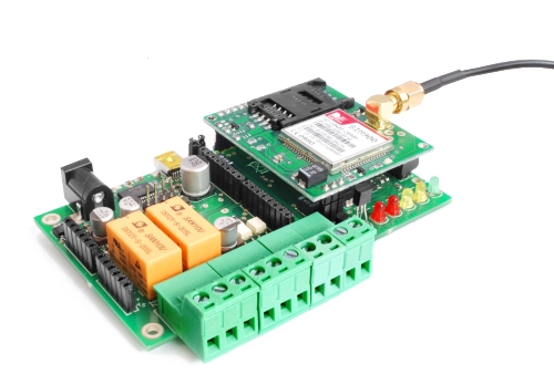
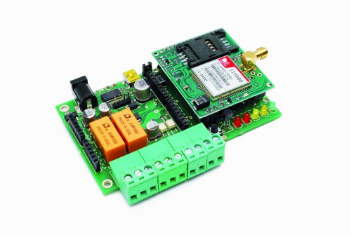
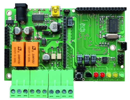
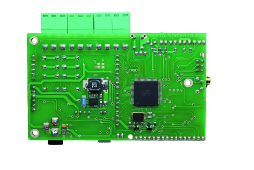
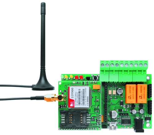
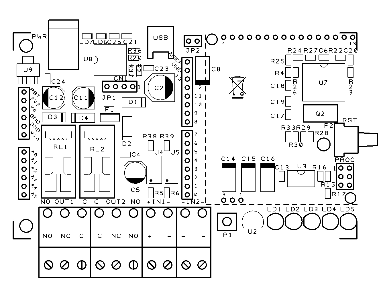
The story starts with the TiDiGino, one of the recent projects based on the ATmega2560, a very well performing mcu with 256kByte of flash memory on board, that is also the core of of the Arduino Mega 2560 board.

The TiDiGino project software has been developed under a contest.

Some out of the participants have been developed high level solutions that took advantage of almost all of the many hardware features of the TiDiGino board.

During development tests they had to notice crashes and malfunctioning that appeared mysterious and very tricky to debug and fix.

After a series of further deep tests and investigation on the support site of ATMEL we have discovered that the main source of our problems was the compiler included in the versions 0022/0023 of the IDE as like as in the current version 1.0.

The compiler program, named “avr-gcc-4.3.2.exe” is not able to compile correctly sketches that require data areas larger than 64kWord, i.e. 128kByte of flash memory.

In simple words the reason is related in the wrong translation of jump instructions beyond 64k.

The compiler we are talking on is the one (version 4.3.2) included in WinAVR package dated from 2008, when the ATMEL microcontroller had on board less than 64kB of memory.

The WinAVR project has been updated on January 2010 with the version “WinAVR-20100110” containing a new version of the compiler, named “avr-gcc-4.3.3.exe”; we tried out this new version too, without success.

The major negative outcome of this issue is that it affects also the Arduino Mega boards both 1280 and 2560 versions, with the effect of limiting the use of data areas larger than 64kWord in sketches. In order to get access to data beyond that limit it is necessary to use the functions of the PROGMEM library, that allow the use of 24bit pointers.

The issue affects only the dimension of data areas, one program that occupies 60kB of data end 60kB of program would run without problem also in the current situation.

After many investigations and tries we find out the solution to this issue, that is to integrate the last version of the ATMEL Toolchain into the Arduino IDE package.

The ATMEL Toolchain is a set of software programs and libraries (tools) that transforms a source code into an executable by a sort of “virtual assembly line”; the output processed by one tool is the input for the following tool in the chain, an so on.

Of course the most important tool in the Toolchain is the compiler, whose last version is currently the “avr-gcc-4.5.1.exe”.


This version is an important enhancement in respect of the one included in the Arduino IDE and offers many advantages:

  1. - supports all the 8bit ATMEL microcontrollers families;
  2. - overcame the 128kB limit and compiles correctly sketches up to 256kB;
  3. - includes best and newest libraries;
  4. - outputs a most compact and efficient compiled object code.


As a completion of this preliminary notes we would focus on the avrdude.exe and avrdude.conf files.

Avrdude.exe is a service program included in the IDE and it is located in the “MyPath\arduino-0022\hardware\tools\avr\bin” folder. The Avrdude.exe version in the Arduino IDE has been modified, respect the AVR original version, in order to support the Arduino bootloaders.

Avrdude.conf is the configuration file that contains the configuration data and settings for each ATMEL microcontroller managed by the IDE, the most advanced users could have been modified this file with the additions of new models of microcontrollers.

Avrdude.conf is located in the “MyPath\arduino-0022\hardware\tools\avr\etc”.

The reason we have mentioned these two files is that they are not involved in the operation of upgrading the Arduino IDE with the compiler in the Toolchain, and have to be carefully saved in a safe place before beginning the upgrading, especially in the step where we will proceed to delete all the contents in the “MyPath\arduino-0022\hardware\tools\avr” folder.

At this point it is possible to describe all the actions needed to execute the upgrading of the IDE.

Our suggestion is to follow the instructions described below, step by step in the provided order and without modification.

The process has been tested many times in order to guarantee the achievement of the result.

Upgrading Arduino IDE process

The process described below is applicable to the Arduino IDE versions 0022, 0023, 1.0, 1.0.1-rc1; the last one listed is the candidate release of IDE 1.0, that is a sort of beta release, still under test; we have processed it too with good results.

Below are the steps to follow:

  1. Copy the whole original IDE folder in a new folder as a backup, in order to maintain the original installation and save the possibility to downgrade the process in case of problem.

  2. Rename the new folder  i.e. arduino-0022-tcnew:


The original folder of the IDE and its copy


  1. In the new folder delete the sub-directory “avr” in “MyPath\arduino-0022-tcnew\hardware\tools”:

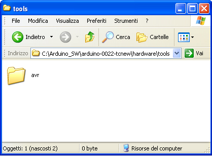
The “avr” directory that has to be deleted

  1. Download the last version of the ATMEL Toolchain for Windows, from the link http://www.atmel.com/tools/ATMELAVRTOOLCHAIN3_2_3FORWINDOWS.aspx; to get access to the download section you must fill an on-line registration form; you will receive an e-mail containing the link to the actual download address:

Download section inside the ATMEL site

  1. Install on your PC in the usual way the downloaded file “avr-toolchain-installer-3.2.3.579-win32.win32.x86.exe”. Take a note of the installation path, in order to easily retrieve the folder in a subsequent moment. If you have a copy of the AVR Studio already installed on your PC, the installation wizard will prompt you with the existing path, in order to get your application upgraded;
  2. Copy from the new installation the directory “AVR Toolchain” and paste it into the folder “MyPath\arduino-0022-tcnew\hardware\tools”; at the end rename the “AVR Toolchain” directory as “avr”. In this way you will get again the original path: “MyPath\arduino-0022-tcnew\hardware\tools\avr”;
  3. Enter the new folder “avr” and delete the sub-directory “avr32”:

The sub-directory “avr32” to be deleted

  1. Copy the file avrdude.exe from the original directory “MyPath\arduino-0022\hardware\tools\avr\bin” and paste it into the folder “MyPath\arduino-0022-tcnew\hardware\tools\avr\bin”. Say “YES” at the warning prompt to overwrite the file;
  2. Copy the whole original directory tree “MyPath\arduino-0022\hardware\tools\avr\etc” and paste it in the folder “MyPath\arduino-0022-tcnew\hardware\tools\avr\;
  3. Delete the sub-directory “include” in ” MyPath\arduino-0022-tcnew\hardware\tools\avr\avr“. Pay attention at the double “avr” directory; there is actually an “avr” subdirectory inside an other “avr” sub-directory as shown in this figure. In place of the deleted sub-directory paste the directory that you can download from our site.

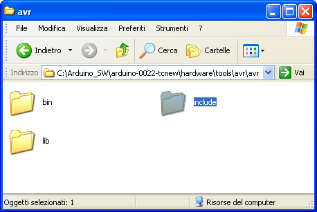
The “include” sub-directory that has to be deleted and substituted with the one downloaded from our site

  1. Now enter the directory “MyPath\arduino-0022-tcnew\examples\”, delete the sub-directory ArduinoISP and the sketch contained in it and add the folder “ArduinoISP101”, that is the new version of that sketch, included in the IDE 1.0.1-rc1. You can download this folder too from here. At the beginning of the process we suggested to you to make a copy of the whole folder of the Arduino IDE; subsequently we drove you in the process of upgrading the copy of the IDE itself. That in order to hold one original version of the IDE that is anyhow useful in case you would get in trouble with the new version. Anyway the original version will always be good to compile applications having a data area smaller than 64kB. Please note that the sketch “ArduinoISP101” has the extension .pde that is correct for the IDE versions 0022 e 0023; in case you are using the version 1.0 you must rename the sketch extension in “.ino” (the new standard adopted by IDE 1.0);

One more warning about the last step: the sketch, that is of interest for all the users running Arduino as an ISP Programmer, works correctly at a BAUD rate of 19200 with the IDE version 0022, 0023; at 9600 BAUD with the version 1.0.1-rc1, and doesn’t work at all with the version 1.0.

According to IDE version that you are using could be needed to change the line Serial.begin(19200);” in “Serial.begin(9600);”.

For the users of version 1.0 of the IDE we have posted in the download section a further version of ArduinoISP, named “ArduinoISP101LM” that is a version of the 1.0.1 patched by two experienced programmers whose names are in the credits list of the sketch.

Be aware that this last version is not an official version and will work with the IDE 1.0 too, at a BAUDRATE of 19200.

In IDE 1.0.1-rc1 environment won’t be mandatory to set the BAUDRATE at 9600 BAUD because the sketch automatically detects the IDE version and sets the port speed accordingly.

As previously described the sketch folder should be placed in the “MyPath\arduino-0022-tcnew\examples\” folder.

Although the sketch is not an official release we can assure that it works quite better than the 101 original, especially in the case you should program MCUs with large memories.

For a better explanation give a glance at the contents of the Table:

Comparison table of the two version of ArduinoISP

As a final note we would warn all the users of the ATtiny family of microcontrollers with the IDE versions 1.0 or 1.0.1 that in same conditions our upgrade could fault the compiling task.

The solution, quite simple, is to add the line “#include <math.h>” as the first instruction in the wiring.h file of the tiny “core”

This solve the problem of the correct priority in the loading of the library chain because math.h has to be loaded as the first library of the chain and not as a dependence of other libraries.

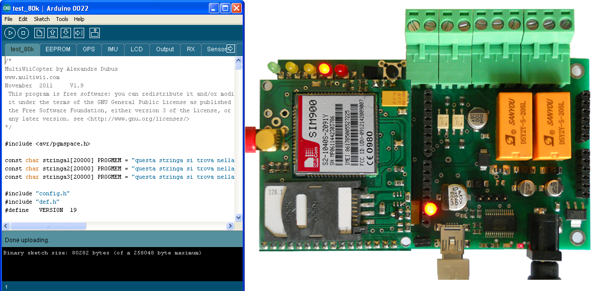
It is time to test this upgrade; if you don’t have at hand one sketch bigger enough to overcame the memory limits described in this article, ever in the download section of our site you could download the sketch “test_80k” that will provide to you the opportunity to proof that the Arduino Mega is now able to run correctly sketches with data areas bigger than 64kB.

The story ends with the test of the software on our TiDiGino project than now run happily.

We will keep you up to date with further news about our tests and investigations on the topic.

Download

Include folder

ArduinoISP101

ArduinoISP101LM

Test 80K

[Thanks to Prof. Michele Menniti & Ing. Marco d’Ambrosio]

Software and firmware for TiDiGino (GSM remote controller with Arduino)

A lot of people who bought the TiDiGino ask me how to test it.
The Gsm Remote Control is provided with bootloader, so you have to insert the prefered sketch that you can find in code.google.
Daniele Denaro wrote a good sketch for TiDiGino, and I’m reporting his tutorial.
Ask me (and him) all do you need.
Author Daniele Denaro

Be careful, because you have to manipulate the environment of development (IDE) 1.0 to insert the new hardware.
In particular replace the file “boards.txt” (see below).
In this new version of the file has been added to the section on hardware TiDiGino.
You should also add the folder “tidigino” that “boards.txt” references (see below).
The changes will be visible to restart the IDE.

Changes from previous version 1.0:

- It was introduced double message mode for alarms. Meaning now is also detected the return to the base level (end alarm) with the possibility to be notified by a second message.

- It is advisable to perform a reset procedure to be safe pressing both the switch P1 and P2 on the first start after installation.

- Fixed some errors in the Java program.

NB. If you have an unmodified hardware TiDiGino, should arrange removal 100-ohm resistor R20 (near the USB connector). Because otherwise…
TiDiGino remains constantly in reset and will not start unless it is also connected to the USB.
(As distinct from the opening of the JP2 jumper that only affects the transparency serial link to the functioning of the operating TiDiGino)

The download includes:
- Installation of this file
- A Italian handbook pdf: TiDiGinoMan.pdf
- A quick Italian reference guide to the controls and the installation and startup: TiDiGinoShort.pdf

- A folder “FirmwareTiDiGino” containing the firmware for TiDiGino;
“TiDiGinoMainV12.ino”: main sketch;
5 modules in the folder “modules”:
“Commands.c”: Commands and their management
“Phone.c” Management Procedures GSM
“Pins.c” Definitions of corresponding pins of the Arduino and global variables
“StateVariables.c” Variables to store the state of the controller and procedures for EEPROM
“Utility.c”: Various procedures used by other modules

- An executable jar file “TiDiGinoW32.jar” and “TiDiGinoW64.jar”
(Containing the Java application interface for Windows32 or Windows64)
(Just extract the files in a directory and appropriate “to click” above)

- A “Library” folder containing (for convenience) Arduino libraries used.
To be installed in the directory “libraries” of the Arduino software (if not already present)

- File “boards.txt” that replaces the same name in the “hardware\arduino”. This file has been added TiDiGino the platform that you will find it listed along with the other (after restarted the IDE). This file is pointing to the directory “Tidigino” of “variants”

- The folder “tdigino” that contains the file “pins_arduino.h” which realizes the map particular hardware of TiDiGino. This folder should be added to other in the templates folder (the folder “hardware\arduino\variants” of the environment Arduino 1.0)

N.B.
To load the sketch of TiDiGino must first edit the path of inclusion forms.
In fact we used the absolute path to solve the problems with the Arduino compiler.
The inclusion of modules is obviously “TiDiGinoMain.ino”.
The easiest thing is to create a folder in the workspace Arduino “TiDiGinoMain”, copy the file “TiDiGinoMain” and the Forms folder, then edit the file, changing paths, and finally activate the upload.
Attention! At the first start after the upload, press P1 and P2 to reset and load the default values ​​to EEPROM.

N.B.
The application interface is in Java (and so you must have Java installed) but it is only for WINDOWS environment because of the library bill for the management of the serial port.
(If the jar was not associated with java you can run it from the console window command “java-jar TiDiGinoWxx.jar”, or creating a link using “javaw-jar TidiGinoWxx.jar”)
Keep in mind that every time you open the serial port you have a firmware restart unless you open jumper JP2 (near the USB connector) that prevents the software reset of Arduino.

N.B.
The software is “open source” and therefore disclaims any liability arising from its use.

TiDiGino, the Arduino-based GSM remote control


Using an ATmega 2560 and therefore the heart of Arduino, we have developed a universal remote control with GSM. This allows  to control 2IN/2OUT, DTMF key, gate control and GSM thermostat activated remotely.

We have already presented several remote control with different functions.
But now we want to present the best remote control ever made with Arduino.
The remote control is easier, thanks to the availability of several libraries that allow you to do anything to the Arduino microprocessor; if there is not really a specific library, you can modify an existing one. Thus was born TiDiGino, based on the chip ATmega 2560 used in Arduino Mega. Our system has connectors S.I.L. to mount any shield, each of them is in the same location where you would be in the original development platform, which enables the use of commercial and in any case the standard shield.
We said that the functions of our remote control, ie 2IN/2OUT, gate opener, key DTMF GSM and thermostat can be achieved by using special firmware, well, we could write these ourselves, but we wanted to offer our readers who know the Arduino environment do them. This is the sense of TiDiGino Contest, which you could follow our blog and that has just ended, as promised, we publish the hardware of the remote control and a few routines.

The circuit

The TiDiGino is based on a ATmega 2560 chip, some pins are used to manage GSM functionality, corresponding to ports that are not used in the original Arduino MEGA. For this reason it is necessary to replace the file pins_arduino.c located under the folder C:\ProgramFiles\arduino-0022\hardware\arduino\cores\arduino that is created by downloading the Arduino IDE, with that we made available with the library, otherwise it is possible to manage all’ATmega 2560 lines of I/O provided by the platform Arduino MEGA.

This choice was intended to leave some I/O free for use by any shield. Therefore you can use the sketches already made to control a specific shield with the original Arduino board, even on TiDiGino.
In compliance with the open-source philosophy we have made available on our site libraries to operate the main blocks of the TiDiGino.
To test the circuit we made four sketches, each of which allows you to use a section of the system. The sketches are all contained in the file GSM_TDGINO.zip, downloadable from the development page of Google, which contains the library that allows you to manage the GSM of TDGINO.
This library comes from the one developed by HWKitchen, but has been adapted to our hardware, as, for example, use the second serial dell’ATMEGA2560 to manage the GSM module of Simcom SIM900. Decompressing the zip in the folder of the Arduino libraries (eg C:\ProgramFiles\arduino-0022\libraries) the library is immediately usable.
By copying the library, are also automatically installed the examples we have developed to manage the various sections, in order to test these examples must be connected to the USB port TDGINO and provide an external power supply circuit of about 12 VDC (1 A of current).
This creates a virtual COM will be used to program the remote control. Select the Board “Arduino Mega 2560″ and from File-> Examples-> GSM_TDGINO, choose the example that you want to upload to the remote control.


The hardware

The I/O used for the expansions are PB4÷PB7, PE3÷PE5, PG5, PH3÷PH6, then there are PE0 and PE1 that are, respectively, RXD and TXD of the first internal UART to the microcontroller.
Now we see the lines of I/O used to manage the devices necessary to implement the functions of remote control, starting from PE6 and PE7 configured as input (pull-up R38 and R39) used to read the status of the optically isolated inputs, each of which detects the presence of a dc voltage (from a minimum of 3 to a maximum of about 35 volts) and AC (from a minimum of 2.5 to a maximum of 30 Vrms) applied to IN1 (circuit U4) and IN2 (circuit U5).
The command of the relay output is obtained with PC0 and PC1, initialized as outputs, each relay is controlled by an NPN transistor.
The GSM in the circuit diagram is not the GSM module, but a circuit (TDGGSM_900 - Store) that mounts it.
There is also a EEPROM memory 24FC256-SN to store user data.
For the management of the temperature sensor, used for the feature “Thermostat GSM”, the ATmega use the pin PK1 initialized as two-way line, the remote temperature sensor used in the Dallas DS1820 is capable of measuring temperatures in the range -5 to 150 ° C with an accuracy of ± 0.5 ° C (-10 to 85 ° C).
The DTMF section use the U7 (a MT8870, SMD): capable to decode standards tone thanks to a complex pattern of active filters agreed by the clock signal generated from its oscillator.
The USB interface circuit uses the integrated U8: the classic FT232RL. The pins 3 (TX) and 2 (RX) correspond to the first UART, since they are essentially used to program TiDiGino thanks the bootloader.
P1 is the button to reset the circuit, which also DTR is forced, by the computer when we want to load the firmware in the micro, exploiting the bootloader.
Well, we conclude the analysis with the power, which is a DC voltage, even non-stabilized (applied to the points + and – PWR) in value between 7 and 32 V, this voltage is filtered downstream of the protection diode reverse polarity (D1) by the capacitors C1 and C2, the fuse F1 allows us to protect the circuit and the source of power in an integrated circuit in the controller below and that we need to derive the 4 volts required to make run the rest of the circuit.

BOM

R1: 0,1 ohm 1W (1206)
R2: 2,2 kohm (0805)
R3: 1 kohm (0805)
R4: 100 kohm (0805)
R5: 4,7 kohm (0805)
R6: 4,7 kohm (0805)
R7: 330 ohm (0805)
R8: 330 ohm (0805)
R9: 4,7 kohm (0805)
R10: 10 kohm (0805)
R11: 4,7 kohm (0805)
R12: 10 kohm (0805)
R13: 330 ohm (0805)
R14: 330 ohm (0805)
R15: 1,5 kohm (0805)
R16: 1,5 kohm (0805)
R17: 330 ohm (0805)
R18: 4,7 kohm (0805)
R19: 4,7 kohm (0805)
R20: 100 ohm (0805)
R21: 4,7 kohm (0805)
R22: 4,7 kohm (0805)
R23: 330 kohm (0805)
R24: 39 kohm (0805)
R25: 56 kohm (0805)
R26: 100 kohm (0805)
R27: 100 kohm (0805)
R28: 4,7 kohm (0805)
R29: 4,7 kohm (0805)
R30: 4,7 kohm (0805)
R31: 0 ohm (0805) *
R32: 0 ohm (0805) *
R33: 4,7 kohm (0805)
R34: 470 ohm (0805)
R35: 470 ohm (0805)
R36: 10 ohm (0805)
R37: 10 ohm (0805)
R38: 4,7 kohm (0805)
R39: 4,7 kohm (0805)

C1: 100 nF (0805)
C2: 220 µF 35 VL (F)
C3: 100 pF (0805)
C4: 100 nF (0805)
C5: 100 µF 16 VL (D)
C6: 100 nF (0805)
C7: 100 nF (0805)
C8: 470 µF 6,3 VL (D)
C9: 22 pF (0805)
C10: 22 pF (0805)
C11: 47 µF 16 VL (D)
C12: 47 µF 16 VL (D)
C13: 100 nF (0805)
C14: 470 µF 6,3 VL (D)
C15: 470 µF 6,3 VL (D)
C16: 470 µF 6,3 VL (D)
C17: 10 pF (0805)
C18: 100 nF (0805)
C19: 10 pF (0805)
C20: 100 nF (0805)
C21: 100 nF (0805)
C22: 4,7 µF 6,3 VL  (R)
C23: 100 nF (0805)
C24: 100 nF (0805)
C25: 100 nF (0805)

Q1: Quartz 16 MHz (C7S)
Q2: Quartz 3,579545 MHz (HC49/4H SMX)

U1: MC34063AD
U2: DS18B20+
U3: 24FC256-SN
U4: TLP181
U5: TLP181
U6: ATMEGA2560-16AU
U7: MT88L70AS
U8: FT232RL
U9: TC1262-3.3 (SOT-223)
GSM: TDGGSM_900

D1: GF1M-E3
D2: MBRS140TRPBF
D3: GF1M-E3
D4: GF1M-E3

T1: BC817
T2: BC817

LD1: LED 3 mm red
LD2: LED 3 mm red
LD3: LED 3 mm yellow
LD4: LED 3 mm yellow
LD5: LED 3 mm green
LD6: LED yellow(0805)
LD7: LED red (0805)

L1: coil 22 µH

RL1: relay 5V 2 vias
RL2: relay 5V 2 vias

P1: Microswitch
P2: Microswitch 90°

F1: Fuse 2 A (1206)

- screw 2 vias(2 pz.)
- screw 3 vias (2 pz.)
- Mini-USB
- Plug
- Jumper
- Strip male 2 poli
- Strip male 3 poli (2 pz.)
- Strip male 4 poli
- Strip female 3 poli
- Strip female 6 poli (2 pz.)
- Strip female 8 poli (2 pz.)
- Strip female 16 poli
- PCB

Functions

There are several sketches to handle the remote control, all came through TiDiGino contest.
These files can be downloaded from Google, where you will find the library and files created by various readers.
Basically all the sketches perform the same functions.
Summarize here the common features.

The remote can be operated by commands sent by SMS, but you can also control it via the serial port (connected to USB converter).
Each command is followed by a response (via SMS) directly to the sender, but the answer may be disabled. In addition there is an alarm function, as the automatic sending of SMS or voice calls, based on conditions on each of the two inputs.
The circuit can also be used as a gate control, calling the SIM in the TiDiGino: the system recognize the calling number and if this number is stored the relay will switch on. In the DTMF mode, the remote control can be controlled by a multi-frequency telephone tone.
In addition, the circuit can operate as a thermostat, running an air conditioning system.

In summary, there are the following features:

• Remote alarm
• Gate control
• GSM termostat
• Remote control with DTMF

Library and sketch

Download the latest sketch for this GSM remote control.

Design