Posts with «esp8266» label

Clock super-display

Today was a good day. In typical fashion, I started a few new "projects" almost in the same time. First one, it's assembling of a new kind of clock, from a kit sent by Nick S. I got stuck pretty early though, so I "parked" it for now. Details to come soon, in a special post.

Second one, an "Adler 121PD" vintage calculator with a VFD display, that I found "in the dumpster" (well, not really, but the idea is the same, I got it for free). I was going to break it apart, for the display and the circuitry, but I gave up when I powered it up (with an improvised cable; the original, proprietary one, was missing) and it actually worked! I may still go ahead with dis-assembling it, since it is not a great value anyway; I checked prices on ebay, and they go for around $20.

Lastly, the project that gave the name of this post: a clock LED super-display, consisting of 3 individual and independent indicators, inspired by the Leitch studio clock, brought to my attention by Nick (VE2HOT). The goal for the clock super-display is to eventually be able to emulate the Leitch clock. Here it is, in its incipient glory (only the back panel; the black wooden frame not pictured):


Since I am not the crafty kind-of-guy (also not keen on spending for form more than for content), I am always looking for cheap, easy and quick solutions for encasing electronics. In this case, Ikea's Ribba 9"x9" frame ($10) seems to be a good fit for the job, and hopefully will help the future clock look "Leitchy" or even better (Nick's photo below):


The 2 alphanumeric displays (4 and 8 chars) of the clock super-display are I2C-driven. The 60 LED ring is adafruit neopixel, controlled by a single pin. With this setup, even an ESP8266 module could be used as the brains of the clock.

The ring is fixed to the cardboard back/panel of the deep Ikea frame with four M3 plastic standoffs glued to the PCB.
The 4-character alphanumeric 16-segment is my creation, introduced earlier. It is driven by the HT16K33 backpack, also from adafruit (not in the picture). The PCB has M3 holes for screws.
The 8-character alphanumeric is made of two side-by-side quad 14-segment LED displays, also from adafruit. The 2 modules already have the HT16K33 drivers installed (soldered on the back). Attaching these quad displays to the panel is not easy, since the holes are probably M1.4. Even these thin M1.4 screws need to be forced, because the screw head presses against display's plastic enclosure. Eventually, the M1.4 screws will be glued to the M3 plastic standoffs, that's the best I could come up with. It is weird that, for such a popular and successful product, one cannot find photos (or instructions) on mounting these modules using screws.

Next step is the software support in the WiFiChron software. Also need to find a way to access the 3 buttons: having them in the back is not a good idea, having them in the front is impossible, unless the glass is replaced with transparent/smoky/grey acrylic, which can be drilled.

Wise time with Arduino 11 May 02:13
esp8266  hdsp  i2c  wifichron  

Clock super-display

Today was a good day. In typical fashion, I started a few new "projects" almost in the same time. First one, it's assembling of a new kind of clock, from a kit sent by Nick S. I got stuck pretty early though, so I "parked" it for now. Details to come soon, in a special post.

Second one, an "Adler 121PD" vintage calculator with a VFD display, that I found "in the dumpster" (well, not really, but the idea is the same, I got it for free). I was going to break it apart, for the display and the circuitry, but I gave up when I powered it up (with an improvised cable; the original, proprietary one, was missing) and it actually worked! I may still go ahead with dis-assembling it, since it is not a great value anyway; I checked prices on ebay, and they go for around $20.

Lastly, the project that gave the name of this post: a clock LED super-display, consisting of 3 individual and independent indicators, inspired by the Leitch studio clock, brought to my attention by Nick (VE2HOT). The goal for the clock super-display is to eventually be able to emulate the Leitch clock. Here it is, in its incipient glory (only the back panel; the black wooden frame not pictured):


Since I am not the crafty kind-of-guy (also not keen on spending for form more than for content), I am always looking for cheap, easy and quick solutions for encasing electronics. In this case, Ikea's Ribba 9"x9" frame ($10) seems to be a good fit for the job, and hopefully will help the future clock look "Leitchy" or even better (Nick's photo below):


The 2 alphanumeric displays (4 and 8 chars) of the clock super-display are I2C-driven. The 60 LED ring is adafruit neopixel, controlled by a single output pin. With this setup, even an ESP8266 module could be used as the brains of the clock.

The ring is fixed to the cardboard back/panel of the deep Ikea frame with four M3 plastic standoffs glued to the PCB.
The 4-character alphanumeric 16-segment is my creation, introduced earlier. It is driven by the HT16K33 backpack, also from adafruit (not in the picture). The PCB has M3 holes for screws.
The 8-character alphanumeric is made of two side-by-side quad 14-segment LED displays, also from adafruit. The 2 modules already have the HT16K33 drivers installed (soldered on the back). Attaching these quad displays to the panel is not easy, since the holes are probably M1.4. Even these thin M1.4 screws need to be forced, because the screw head presses against display's plastic enclosure. Eventually, the M1.4 screws will be glued to the M3 plastic standoffs, that's the best I could come up with. It is weird that, for such a popular and successful product, one cannot find photos (or instructions) on mounting these modules using screws.

Next step is the software support in the WiFiChron software. Also need to find a way to access the 3 buttons: having them in the back is not a good idea, having them in the front is impossible, unless the glass is replaced with transparent/smoky/grey acrylic, which can be drilled.

Wise time with Arduino 11 May 02:13
esp8266  hdsp  i2c  wifichron  

Library Makes ESP Over the Air Updates Easy

Potentially, one of the great things about having a device connected to the network is that you can update it remotely. However, how do you make that happen? If you use the Arduino setup for the ESP8266 or ESP32, you might try [scottchiefbaker’s] library which promises to make the process easy.

Adding it looks to be simple. You’ll need an include, of course. If you don’t mind using port 8080 and the path /webota, you only need to call handle_webota() from your main loop. If you want to change the defaults, you’ll need to add an extra call in your setup. You also need to set up a few global variables to specify your network parameters.

The only caveat is that long delay statements in your loop can block things from working and aren’t a great idea anyway. If you have them, you can replace all your delay calls with webota_delay which will stop the system from ignoring update requests.

The code started from a different online tutorial but packaged the code up nicely for reuse. To do an update, simply navigate to the device with a web browser and use the correct port number and path. From there you can upload a new binary image taken from the Arduino IDE with the export compiled binary command.

The only concern we saw was the code didn’t appear to authenticate you at all. That means anyone could load code into your ESP. That might be ok on a private network, but on the public Internet it is surely asking for trouble. The original tutorial code did have a hardcoded user and password, but it didn’t look very useful as the password was in the clear and didn’t stop you from uploading if you knew the right URL. Dropping it from the library probably makes sense, but we would want to build some kind of meaningful security into anything we deployed.

If you have a network connection, we’ve seen the same trick done with a normal Arduino with a wireless chip. You can even do it over WiFi but using an ESP8266 which you’ll then want to be able to update, too.

Hack a Day 21 Mar 09:00

Demystifying The ESP8266 With A Series Of Tutorials

If your interest has been piqued by the inexpensive wireless-enabled goodness of the ESP8266 microcontroller, but you have been intimidated by the slightly Wild-West nature of the ecosystem that surrounds it, help is at hand. [Alexander] is creating a series of ESP8266 tutorials designed to demystify the component and lead even the most timid would-be developer to a successful first piece of code.

If you cast your mind back to 2014 when the ESP8266 first emerged, it caused great excitement but had almost no information surrounding it. You could buy it on a selection of modules, but there were no English instructions and no tools to speak of. A community of software and hardware hackers set to work, resulting in a variety of routes into development including the required add-ons to use the ever-popular Arduino framework. Four years later we have a mature and reliable platform, with a selection of higher-quality and well supported boards to choose from alongside that original selection.

The tutorials cover the Arduino and the ESP, as well as Lua and the official SDK. They are written for a complete newcomer, but the style is accessible enough that anyone requiring a quick intro to each platform should be able to gain something.

Our community never ceases to amaze us with the quality of the work that emerges from it. We’ve seen plenty of very high quality projects over the years, and it’s especially pleasing to see someone such as [Alexander] giving something back in this way. We look forward to future installments in this series, and you should keep an eye out for them.

Hack a Day 26 Aug 18:01

Why Have Only One Radio, When You Can Have Two?

There are a multitude of radio shields for the Arduino and similar platforms, but they so often only support one protocol, manufacturer, or frequency band. [Jan Gromeš] was vexed by this in a project he saw, so decided to create a shield capable of supporting multiple different types. And because more is so often better, he also gave it space for not one, but two different radio modules. He calls the resulting Swiss Army Knife of Arduino radio shields the Kite, and he’s shared everything needed for one on a hackaday.io page and a GitHub repository.

Supported so far are ESP8266 modules, HC-05 Bluetooth modules, RFM69 FSK/OOK modules, SX127x series LoRa modules including SX1272, SX1276 and SX1278, XBee modules (S2B), and he claims that more are in development. Since some of those operate in very similar frequency bands it would be interesting to note whether any adverse effects come from their use in close proximity. We suspect there won’t be because the protocols involved are designed to be resilient, but there is nothing like a real-world example to prove it.

This project is unique, so we’re struggling to find previous Hackaday features of analogous ones. We have however looked at an overview of choosing the right wireless tech.

Hack a Day 28 Jul 09:00

Tubby Bot a Wifi/Smartphone controlled two wheeled bot – STEP BY STEP GUIDE

Let's Make Robots 05 Jul 20:09
arduino  esp8266  wifi  

Need a Thousand Extra PWM Pins?

If your Arduino runs out of I/O lines, you can always add one of the several I/O expander chips that takes a serial interface to set its several pins. Or perhaps you could buy something like an Arduino Mega, with its extra sockets to fulfil your needs. But what would you do if you really needed more pins, say a thousand of them? Perhaps [Brian Lough] has the answer. OK, full disclosure: If you really need a thousand, the video isn’t exactly for you, as he shows you how to add up to 992 PWM outputs. The chip he uses works with any microcontroller (the video shows an ESP8266), and we suppose you could use two daisy chains of them and break the 1,000 barrier handily.

We like how short the video is (just two minutes; see below) as it gets right to the point. The PCA9685 chip gives you 16 12-bit PWM channels via an I2C interface. You can daisy chain up to 62 of the boards to get the 992 outputs promised.

[Brian] uses a cheap $2 breakout board that lets you set a 6-bit address, has a nice power connector and makes it easy to use the little surface mount device. Each of the 16 outputs on the board can have an independent duty cycle, but they do share a single output frequency. That means if you want to use some channels for low-frequency devices like motors and some for high-frequency devices like LEDs, you might have to spring $4 for two boards.

Over on Hackaday.io, we’ve seen these devices driving 128 vibration motors. The PCA9685 made us think of the time we rolled our own serial to PWM devices using an FPGA.

Hack a Day 12 Apr 00:00

Arduino Trivia Box is a Gift Unto Itself

There’s something about impressing strangers on the Internet that brings out the best in us. Honestly, we wouldn’t be able to run this site otherwise. A perfect example of this phenomenon is the annual Reddit Secret Santa, where users are challenged to come up with thoughtful gifts for somebody they’ve never even met before.

For his entry into this yearly demonstration of creativity, [Harrison Pace] wanted to do something that showcased his improving electronic skills while also providing something entertaining to the recipient. So he came up with a box of goodies which is unlocked by the successful completion of a built-in trivia game tailored around their interests. If this is how he treats strangers, we can’t wait to see what he does for his friends.

Hardware packed into the lid so the box itself remains empty.

There’s quite a bit of hardware hidden under the hood of this bedazzled gift box. The primary functions of the box are handled by an Arduino Nano; which runs the trivia game and provides user interaction via a 16×2 LCD, three push buttons, and a buzzer. Once the trivia game is complete, a servo is used to unlock the box and allow the recipient access to the physical gifts.

But that’s not the only trick this box has hidden inside. Once the main trivia game is complete, a ESP8266 kicks into action and advertises an access point the user can connect to. This starts the second level of challenges and gifts, which includes a code breaking challenge and gifted software licenses.

The project wasn’t all smooth sailing though. [Harrison] admits that his skills are still developing, and there were a few lessons learned during this project he is unlikely to forget in the future. Some Magic Smoke managed to escape when he connected his 5V Arduino directly to the 3.3V ESP8266, but at least it was a fairly cheap mistake and he had spares on hand to get the project completed anyway.

This project is reminiscent of reverse geocache boxes which only open when moved to a certain location, but the trivia aspect makes it perfect even for those of us who don’t want to put pants on just to receive our Internet gifts.


Filed under: Arduino Hacks, Holiday Hacks

Dumb STB gets smart

[Vincent Deconinck] gave a fresh lease of life to an old set top box by adding a few Euro’s worth of hardware and some software smarts. The device in question is an old VOOcorder – a Cisco set-top box provided by VOO, his cable service provider in Belgium.

The VOOcorder doesn’t have any WiFi hardware or browser / app based interfaces. It’s a simple device controlled either via an IR remote or front panel buttons. [Vincent] added an ESP8266 and hooked it up to the IR receiver on the set-top box. He also set it up as an SPI slave to the front panel VFD display controller and connected it to the debug serial interface of the VOOcorder as well. The software, on the other hand, required a lot more work consisting of code running on the ESP itself, several HTML pages and JavaScript code for the browser front end, and a few scripts running in the background.

The result was bidirectional interactivity from within a browser, allowing him to send commands and receive status information as well as providing a user-friendly search interface. Further, his browser interface was integrated with information from the service providers website letting him do scheduling and recording of programs. The stuff that interested us is how he sniffed out the IR signals, figured out the SPI protocol used by the front panel controller, and implemented SPI-slave mode for the ESP8266. [Vincent] was surprised that such a cheap device could handle three distinct web servers while parsing two message streams without a hitch.

It’s a great hack showing us how to use super cheap electronics to upgrade and modernize old hardware. Check out the two videos after the break – showing a demo of the hack in action, and a walk through of the hardware modifications.


Filed under: hardware, home entertainment hacks

Getting Started with NodeMCU3

Hello Friends,

Today we will write first program for NodeMCU3 that is led blinking. NodeMCU3 has esp12e and ch340 (USB-TTL) on-board. It can be connected to PC/ Laptop via USB mini(type B) data cable.

Let's get started.

All we need is NodeMCU3 and arduino IDE.
LED and resistor


First of all, install required library for nodemcu and install the driver for ch340.

Go to this link for driver installation

Download

After downloading, install the driver.

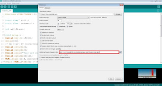
Open Arduino IDE, in File menu go to preferences, additional board manager URL, type

http://arduino.esp8266.com/stable/package_esp8266com_index.json

Preferences

Now, we have to install board,
check this video:

Finally upload the program.

Voila! led is blinking

FunWithElectronics 12 Aug 07:33
esp8266  nodemcu