Microcontrollers, Meet MicroBlocks
 Physical Computing Software For Education That Runs Live, On The Microcontroller
The post Microcontrollers, Meet MicroBlocks appeared first on Make: DIY Projects and Ideas for Makers.


Physical Computing Software For Education That Runs Live, On The Microcontroller
The post Microcontrollers, Meet MicroBlocks appeared first on Make: DIY Projects and Ideas for Makers.
You don’t have to be an extinct mammal or a Millennial to enjoy the smooth, buttery taste of an avocado. Being psychic on the other hand is definitely an advantage to catch that small, perfect window between raw and rotten of this divaesque fruit. But don’t worry, as modern problems require modern solutions, [Eden Bar-Tov], [Elan Goldberg], and [Mizpe Ramon] built the AvoRipe, a device to notify you when your next avocado has reached that window.
Taking both the firmness and color of an avocado as indicators of its ripeness into account, the team built a dome holding a TCS3200 color sensor as stand for the avocado itself, and 3D printed a servo-controlled gripper with a force sensor attached to it. Closing the gripper’s arms step by step and reading the force sensor’s value will determine the softness the avocado has reached. Using an ESP8266 as centerpiece, the AvoRipe is turned into a full-blown IoT device, reporting the sensor readings to a smartphone app, and collecting the avocado’s data history on an Adafruit.IO dashboard.
There is unfortunately one big drawback: to calibrate the sensors, a set of nicely, ripe avocados are required, turning the device into somewhat of a chicken and egg situation. Nevertheless, it’s a nice showcase of tying together different platforms available for widescale hobbyist projects. Sure, it doesn’t hurt to know how to do each part from scratch on your own, but on the other hand, why not use the shortcuts that are at our disposal to remove some obstacles — which sometimes might include programming itself.
The SPINES (Self-Powered IoT Node for Environmental Sensing) Mote is a wireless IoT environmental sensor, but don’t let the neatly packed single PCB fool you into thinking it’s not hackable. [Macro Yau] specifically designed SPINES to be highly modular in order to make designing an energy harvesting sensor node an easier task. The way [Macro] sees it, there are two big hurdles to development: one is the energy harvesting itself, and the other is the software required to manage the use of every precious joule of that harvested energy.
[Macro] designed the single board SPINES Mote in a way that the energy harvesting portion can be used independently, and easily integrated into other designs. In addition, an Arduino library is being developed to make it easy for the power management to be done behind the scenes, allowing a developer to concentrate on the application itself. A solar-powered wireless sensor node is one thing, but helping people get their ideas up and running faster in the process is wonderful to see.
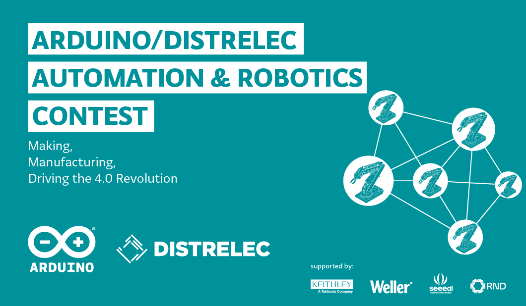
How can you help advance Industry 4.0 using the Arduino ecosystem? From robots and predictive maintenance to remote control and data acquisition, we’ve teamed up Distrelec to launch a new Automation & Robotics Contest challenging our community to create innovative solutions that can make the industry faster, cheaper, more flexible, and efficient.
Participants are required to tap into our extensive range of IoT boards like the MKR1000 WiFi and MKR GSM 1400, libraries, and online platform to bring their ideas to life. Industrial automation projects could target energy management, remote monitoring, machine safety, or predictive maintenance, for example, using Arduino Create to set up, control, and connect your Arduino, Intel, and Arm-based devices. Robotics projects could include designs for surveillance drones, robotic arms, rovers, or autonomous transportation, leveraging feature-rich boards like the Mega and Due to prototype advanced systems.
How to Enter
Prizes
Ready to get started? You can find more information on the contest here and browse Distrelec’s entire Arduino lineup on their website. To submit your ideas, please visit the Arduino Project Hub. And remember, projects must use an Arduino board in order to be eligible to win!
Back in the olden days, when the Wire library still sucked, the Arduino was just a microcontroller. Now, we have single board computers and cheap microcontrollers with WiFi built in. As always, there’s a need to make programming and embedded development more accessible and more widely supported among the hundreds of devices available today.
At the Embedded Linux Conference this week, [Massimo Banzi] announced the beginning of what will be Arduino’s answer to the cloud, online IDEs, and a vast ecosystem of connected devices. It’s Arduino Create, an online IDE that allows anyone to develop embedded projects and manage them remotely.
As demonstrated in [Massimo]’s keynote, the core idea of Arduino Create is to put a connected device on the Internet and allow over-the-air updates and development. As this is Arduino, the volumes of libraries available for hundreds of different platforms are leveraged to make this possible. Right now, a wide variety of boards are supported, including the Raspberry Pi, BeagleBone, and several Intel IoT boards.
The focus of this development is platform-agnostic and focuses nearly entirely on ease of use and interoperability. This is a marked change from the Arduino of five years ago; there was a time when the Arduino was an ATmega328p, and that’s about it. A few years later, you could put Arduino sketches on an ATtiny85. A lot has changed since then. We got the Raspberry Pi, we got Intel stepping into the waters of IoT devices, we got a million boards based on smartphone SoCs, and Intel got out of the IoT market.
While others companies and organizations have already made inroads into an online IDE for Raspberry Pis and other single board computers, namely the Adafruit webIDE and Codebender, this is a welcome change that already has the support of the Arduino organization.
You can check out [Massimo]’s keynote below.

In this project I will
 Ahmet Akif Kaya built a system. that incorporates an Arduino, Bluetooth module, and servo. to control his light switch from his cel phone.
The post Control Your Light Switches from Your Phone appeared first on Make: DIY Projects and Ideas for Makers.
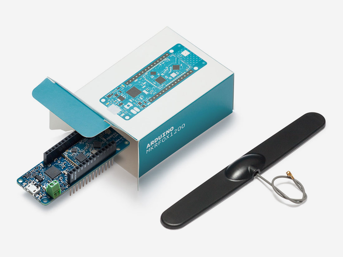
On Arduino Day, we announced the latest member of the Arduino MKR family: the MKRFOX1200. This powerful IoT development board offers a practical and cost effective solution for Makers looking to add Sigfox connectivity to their projects with minimal previous networking experience.
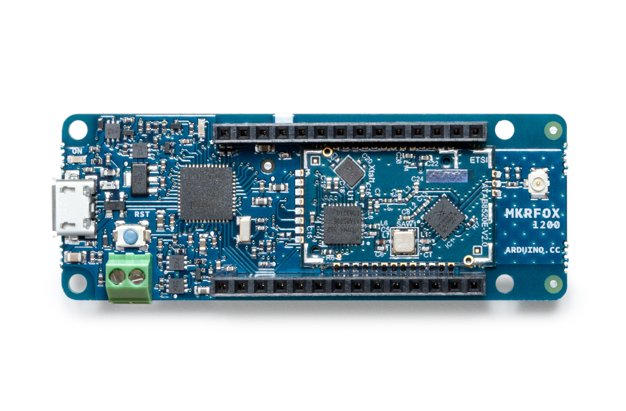
The MKRFOX1200 shares several similarities with other MKR products, like the MKR1000 and MKRZero, including a compact form factor (67 x 25mm) and a Microchip SAM D21 32-bit Cortex-M0+ microcontroller at its core. The recently unveiled board also features an ATA8520 module for long-range, low-energy consumption, and is capable of running for over six months on two standard AA 1.5V batteries.
Designed for Makers ready to take their IoT projects into the real world, the MKRFOX1200 comes with a GSM antenna that can be attached to the board and a two-year subscription to the Sigfox network. This provides users with full access to Sigfox’s efficient messaging system (up to 140 messages per day), cloud platform, webhooks, APIs, as well as the new Spot’it geolocation service.
MKRFOX1200 can be used in a wide variety of settings, from agriculture (livestock management, smart irrigation and weather stations), to smart cities (dumpster monitoring, air quality networks, street lighting or parking lot tracking), to utility metering and other industrial applications.
“Sigfox loves Makers,” says Nicolas Lesconnec, Head of Developer Relations. “Sigfox aims to empowers billions of new IoT solutions. We’re proud to partner with Arduino, the leading open-source electronics platform, to offer the simplest way to connect anything.”
Sigfox currently operates in over 30 countries, with more to follow in the next few years. (Use this map to see whether it has been deployed or is rolling out in your area.) The first version of the MKRFOX1200 is compatible with Sigfox Radio Configuration Zone 1 (868MHz, 14dBm), meaning it is only supported in network-covered regions of Europe, the Middle East, and South Africa.
Interested? You can find the MKRFOX1200’s specs here, and watch Massimo Banzi’s overview below. The board is now available on Arduino’s European online store!
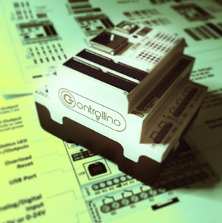
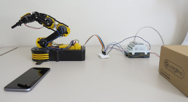
This tutorial will show you how to take over the controls of the OWI Robotic Arm with the help of an Arduino compatible, open-source PLC called the Controllino MAXI, together with Cayenne (my go-to iOT application for remote connection to my Arduino projects). The Controllino MAXI will provide the physical connections to the OWI robotic arm, and Cayenne will allow me to control the arm via my web browser or via the Cayenne app on my phone.
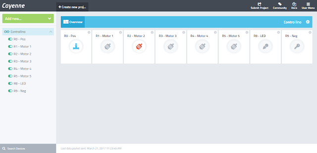
The code above is very simple, however you will need to create a dashboard of widgets from within your Cayenne account in order to control the OWI robotic Arm from your phone or via the Dashboard webpage.
Once you have created your Cayenne account, you will be presented with a webpage to choose a board to connect to. Controllino is an Arduino compatible PLC, so make sure to follow these instructions for setting up the Controllino in your Cayenne Account.
After you upload the code to the Controllino, and providing it has an ethernet cable connected to the internet router (and has access to the internet), and is powered on, it will connect to your Cayenne Dashboard. You can now add widgets to the dashboard in real time to interact with the Controllino, and without uploading any more code to the open source PLC.
We need to add a number of widgets in order to activate the relays on the Controllino. The relavent digital pins that we will need to know about can be found on the Controllino website here: https://controllino.biz/downloads/.
Here is the direct link to the PINOUT file for the Controllino MAXI.
"Armed" with that knowledge, we can now create the widgets which are necessary to control the relays on the Controllino. From within the Cayenne dashboard, please follow these instructions to create a widget:
You should now see your new widget on the dashboard. Select the widget to enable or activate that relay. If you do this, and if everything goes to plan, you will see the LED for R0 illuminate on the Controllino. You now have to add the rest of the widgets to the dashboard in order to control the rest of the relays on the Controllino.
Here is a table to show you how I setup my dashboard.


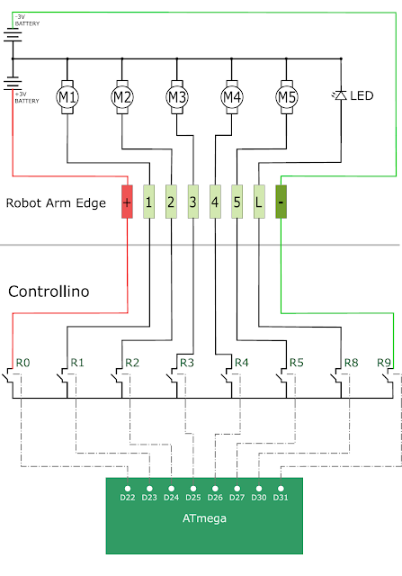
The following circuit diagram will show you how the wired control box is normally connected to the OWI Robotic arm. This is the circuit diagram of the OWI robotic arm under normal operating contidtions.

The following circuit diagram will show you how the OWI Robotic Arm will be controlled by the relays of the Controllino. This is the circuit diagram of the OWI robotic arm when it is connected to the Controllino.
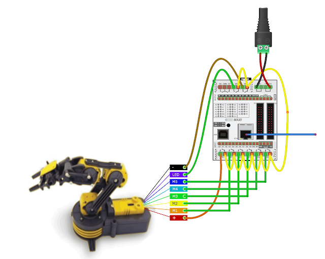
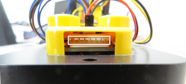
The OWI Robotic Arm is connected to a breadboard using the female-to-male jumper wires. Solid core wire is then fed through to the relay terminals of the Controllino. You could just wire it up so that the robotic arm is connected directly to the Controllino, however, I did not have the right connectors for this purpose.
The Controllino is also connected to my internet router via a normal RJ-45 ethernet cable, and is powered by a 12V DC power adapter.
Now that you have all the physical connections made, uploaded the code to the Controllino, and have created your dashboard in Cayenne, you should be able to control your OWI Robotic arm from anywhere in the world. As demonstrated in the video at the start of this tutorial, the robotic arm has quite a bit of give on each of the joints, which makes it difficult to achieve certain tasks that require an element of precision. There goes that idea of being able to perform surgery with this thing !!! At least you can get it to make you a cup of tea, and if you are patient enough, you might even get a grape once in a while.
Thank you to Controllino and Cayenne for making this tutorial possible. If you would like your product featured in my tutorials, please contact me on my contact page.