Today’s class in the freshman design seminar went well. I started by returning the drafts of the design reports and giving some generic feedback. I realized on reading the reports that I had not given a good explanation of what I meant by describing the components of the system—two of the groups had given me long parts lists on the first page of their reports, something that would only really be appropriate in an appendix. I explained that what I wanted was what the main blocks in the block diagram were, and that they should use the block diagram to organize their report, writing a page for each block. I also suggested that they use the block diagram to partition the project among the group members, with each group member working on a different component, then getting back together to reconcile any discrepancies. Note that this is much more like real engineering group work than the usual K–12 group project, which is usually done most efficiently by turning the whole project over to the most competent member of the group.
After the feedback on design reports, I offered the students a chance to get a demo of building an Arduino program with sensing and motor control. This was a completely extemporaneous demo—I had gathered a number of possibly useful components, but had not tested anything ahead of time nor even figured out what order to do the demo in. I asked the students if they wanted me to start with sensing or control—they asked for the motor control first.
I started by pulling a motor out of box of motors I had gotten when the elementary school my wife works at cleaned out their closets. I told the students that I had no idea what the spec of the motor were, but since it came from an elementary school, it probably ran on 3v batteries. I tested the motor by hooking it up first to the 3.3v, then to the 5v power on my Arduino Uno. It spun just fine on 3.3v, but squealed a bit on 5v, so we decided to run it on 3.3v.
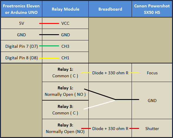
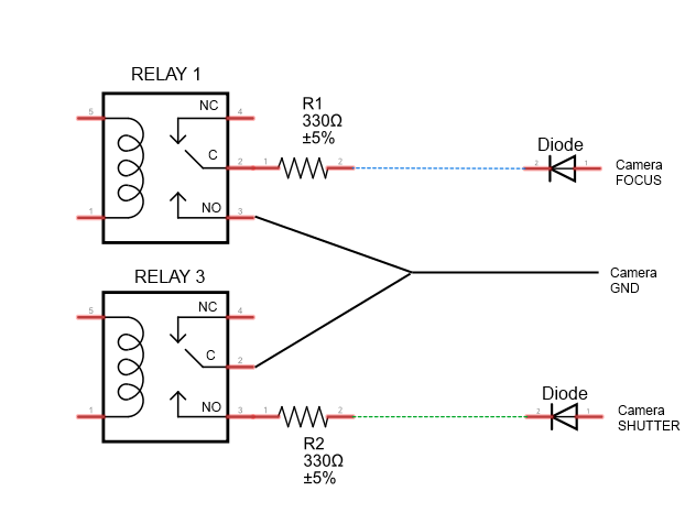
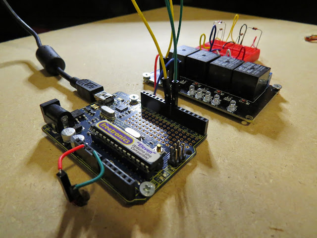
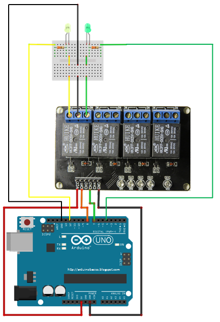
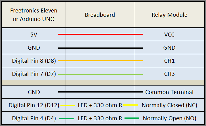
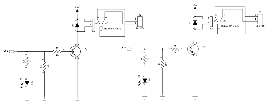
I then pulled out the Sainsmart 4-relay board that I had bought some time ago but never used. I explained how a relay worked, what single-pole double-throw meant, and normally open (NO) and normally closed (NC) contacts. I used the board unpowered with the NC contacts to spin the motor, then moved the wire over to the NO contacts to turn the motor off. I then hooked up power to the board and tried connecting input IN1 to power to activate the relay. Nothing happened. I then tried connecting IN1 to ground, and the relay clicked and the motor spun. The inputs to the Sainsmart board are active low, which I explained to the students (though I did not use the terminology “active low”—perhaps I should have). I did make a point of establishing that the relay provides very good isolation between the control logic and the circuitry being controlled—you can hook up AC power from the walls to the relay contacts without interfering with the logic circuitry.
Having established that the relay worked, the next step was to get the class (as a group) to write an Arduino program to control the motor using the relay. With me taking notes on the whiteboard, they quickly came up with the pinMode command for the setup, the digitalWrite and delay for the loop, and with only a tiny bit of prompting with a second digitalWrite and delay to turn the motor back off. They even realized the need to have different delays for the on and off, so we could tell whether we had the polarity right on the control. Here is the program we came up with:
#define RELAY_PIN (3)

void setup()
{   pinMode(RELAY_PIN, OUTPUT);
}

void loop()
{
  digitalWrite(RELAY_PIN,LOW); // turn motor ON via relay (or off via transistor)
  delay(1000);  // on for 1 second
  digitalWrite(RELAY_PIN,HIGH); // turn motor OFF via relay (or on via transistor)
  delay(3000); // off for 3 seconds
}
I typed the code in and downloaded it to the Arduino Uno, and it worked as expected. (It would be nice if the Arduino IDE would allow me to increase the font size, like almost every other program I use, so that students could have read the projection of what I was typing better.)
I then offered the students a choice of going on to sensing or looking at pulse-width modulation for proportional control. They wanted PWM. I explained why PWM is not really doable with relays (the relays are too slow, and chattering them would wear them out after a while. I did not have the specs on the relay handy, but I just looked up the specs for the SRD-05VDC-SL-C relays on the board: They have a mechanical life of 10,000,000 cycles, but an electrical life of only 100,000 cycles. The relay takes about 7msec to make a contact and about 3msec to break a contact, so they can’t be operated much faster than about 60 times a second, which could wear them out in as little as half an hour.
So instead of a relay, I suggested an nFET (Field-Effect Transistor). I gave them a circuit with one side of the motor connected to 3.3V, the other to the drain of an nFET, with the source connected to ground. I explained that the voltage between the gate and the source (VGS) controlled whether the transistor was on or off, and that putting 5v on the gate would turn it on fairly well. I then got out an AOI518 nFET and stuck it in my breadboard, explaining the orientation to allow using the other holes to connect to the source, gate, and drain.
I mentioned that different FETs have the order of the pins different, so one has to look up the pinout on data sheet. I pulled up the AOI518 data sheet, which has on the first page “RDS(ON) (at VGS = 4.5V) < 11.9mΩ”. I explained that if we were putting a whole amp through the FET (we’re not doing anywhere near that much current), the voltage drop would be 11.9mV, so the power dissipated in the transistor would be only 11.9mW, not enough to get it warm. I mentioned that more current would result in more power being dissipated (I2R), and that the FETs could get quite warm. I passed around my other breadboard which has six melted holes from FETs getting quite hot when I was trying to debug the class-D amplifier design. The students were surprised that the FETs still worked after getting that hot (I must admit that I was also).
I hooked up the AOI518 nFET using double-headed male header pins and female jumper cables, and the motor alternated on for 3 seconds, off for one second. We now had the transistor controlling the motor, so it was time to switch to PWM. I went to the Arduino reference page and looked around for PWM, finding it on analogWrite(). I clicked that link and we looked at the page, seeing that analog Write was like digitalWrite, except that we could put in a value from 0 to 255 that controlled what fraction of the time the pin was high.
I edited the code, changing the first digitalWrite() to analogWrite(nFET_GATE_PIN, 255), and commenting out the rest of the loop. We downloaded that, and it turned the motor on, as expected. I then tried writing 128, which still turned the motor on, but perhaps not as strongly (hard to tell with no load). Writing 50 resulted in the motor not starting. Writing 100 let the motor run if I started it by hand, but wouldn’t start the motor from a dead stop. I used this opportunity to point out that controlling the motor was not linear—1/5th didn’t run at 1/5th speed, but wouldn’t run the motor at all.
Next we switched over to doing sensors (with only 10 minutes left in the class). I got out the pressure sensor and instrumentation amp from the circuits course and hooked it up. The screwdriver I had packed in the box had too large a blade for the 0.1″ screw terminals, but luckily the tiny screwdriver on my Swiss Army knife (tucked away in the corkscrew) was small enough. After hooking up the pressure sensor to A0, I downloaded the Arduino Data Logger to the Uno, and started it from a terminal window. I set the triggering to every 100msec (which probably should be the default for the data logger), the input to A0, and convert to volts. I then demoed the pressure sensor by blowing into or sucking on the plastic tube hooked up to the sensor. With the low-gain output from the amplifier, the output swung about 0.5 v either way from the 2.5v center. Moving the A0 wire over to the high-gain output of the amplifier gave a more visible signal. I also turned off the “convert to volts” to show the students the values actually read by the Arduino (511 and 512, the middle of the range from 0 to 1023).
Because the class was over at that point, I offered to stay for another 10 minutes to show them how to use the pressure sensor to control the motor. One or two students had other classes to run to, but most stayed. I then wrote a program that would normally have the motor off, but would turn it full on if I got the pressure reading up to 512+255 and would turn it on partway (using PWM) between 512 and 512+255. I made several typos when entering the program (including messing up the braces and putting in an extraneous semicolon), but on the third compilation it downloaded successfully and controlled the motor as expected.
One student asked why the motor was off when I wasn’t blowing into the tube, so I explained about 512 being the pressure reading when nothing was happening (neither blowing into the tube nor sucking on it). I changed the zero point for the motor to a pressure reading of 300, so that the motor was normally most of the way on, but could be turned off by sucking on the tube. Here is the program we ended up with
#define nFET_GATE_PIN (3)

void setup()
{   pinMode(nFET_GATE_PIN, OUTPUT);
    pinMode(A0, INPUT);
}

void loop()
{ int pressure;
  pressure=analogRead(A0);
  if (pressure < 300)
  {    digitalWrite(nFET_GATE_PIN,LOW);  // turn motor off
  }
  else
  {   if (pressure>300+255)
      { digitalWrite(nFET_GATE_PIN,HIGH);  // turn motor on full
      }
      else
      {    analogWrite(nFET_GATE_PIN,pressure-300); // turn motor partway on
      }
  }
}
Note: this code is not an example of brilliant programming style. I can see several things that I would have done differently if I had had time to think about the code, but for this blog it is more useful to show the actual artifact that was developed in the demo, even if it makes me cringe a little.
Overall, I thought that the demo went well, despite being completely extemporaneous. Running over by 10 minutes might have been avoidable, but only by omitting something useful (like the feedback on the design reports). The demo itself lasted about 70 minutes, making the whole class run 80 minutes instead of 70. I think I compressed the demo about as much as was feasible for the level the students were at.
Based on how the students developed the first motor-control program quickly in class, I think that some of them are beginning to get some of the main ideas of programming: explicit instructions and sequential ordering. Because we were out of time by the point I got to using conditionals, I did not get a chance to probe their understanding there.
Filed under:
freshman design seminar,
Pressure gauge Tagged:
Arduino,
FET,
motor,
nMOS FET,
pressure sensor,
PWM,
relay 


 This plug-and-play rig will make it easy to control high-voltage outputs from a low-voltage Arduino.