

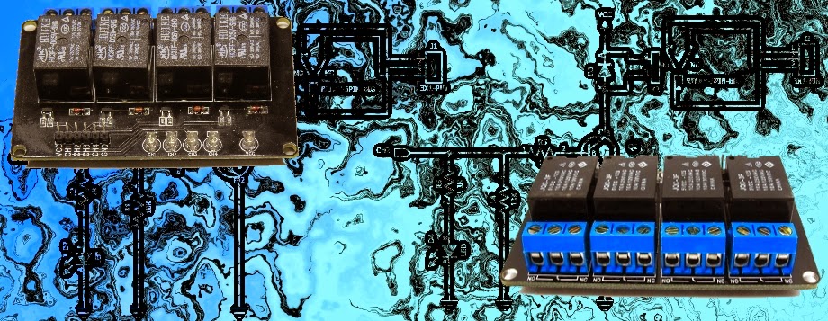
Relay Module
WARNING: Mishandling or incorrect or improper use of relays could result in
- serious personal injury or DEATH
- possible physical damage of the product
- faulty operation
- or create serious/dangerous hazards.
Please make sure that you read and understand how your relay/relay module board works, the voltage and current it is rated for, and the risks involved in your project BEFORE you even attempt to start putting it together. Seek professional and qualified assistance BEFORE you undertake ANY high power projects.
If you choose to follow the instructions in this tutorial, you do so at your own risk. I am not an electrician, and am not a qualified electrical engineer - so please do your research and seek advice BEFORE undertaking a project using a relay. Please check your connections and test them BEFORE turning the power on.
I accept no responsibility for your project, or the risk/damage/fire/shock/injury/death/loss that it causes. You take full responsibility for your actions/project/creation, and do so at YOUR OWN RISK !!!
Please note: It is illegal in some countries to wire up a high power project without an electrician. Please check your country's rules/laws/regulations before you undertake your project. If you have any doubts - don't do it.
What is a relay
A Relay is an electrically operated switch. Many relays use an electromagnet to mechanically operate the switch and provide electrical isolation between two circuits. In this project there is no real need to isolate one circuit from the other, but we will use an Arduino UNO to control the relay. We will develop a simple circuit to demonstrate and distinguish between the NO (Normally open) and NC (Normally closed) terminals of the relay. We will then use the information gained in this tutorial to make a much more exciting circuit. But we have to start somewhere. So let's get on with it.
Parts Required:
- Freetronics Eleven or (Arduino UNO compatible board)
- 4 Channel Relay Module
- 2x LEDs
- 2x 330 ohm resistors
- Jumper Wires (male to male)
- Jumper Wires (female to male)
Fritzing Sketch
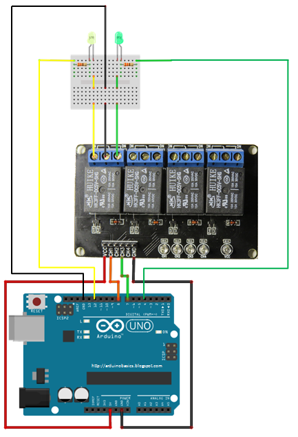
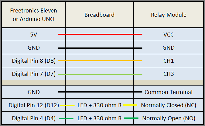
Table of Connections
Arduino Sketch
1 |
|
The Red light on the Relay board turns on when power is applied (via the VCC pin). When power is applied to one of the Channel pins, the respective green light goes on, plus the relevant relay will switch from NC to NO. When power is removed from the channel pin, the relay will switch back to NC from NO. In this sketch we see that power is applied to both LEDs in the setup() method. When there is no power applied to the CH1 pin, the yellow LED will be on, and the Green LED will be off. This is because there is a break in the circuit for the green LED. When power is applied to CH1, the relay switches from NC to NO, thus closing the circuit for the green LED and opening the circuit for the yellow LED. The green LED turns on, and the yellow LED turns off.
I also show what happens when you apply power to a channel (eg. CH3) when there is nothing connected to the relay terminals. The respective onboard LED illuminates. This is useful for troubleshooting the relays, and knowing what state the relay is in (NC or NO). NC stands for Normally closed (or normally connected) NO stands for Normally open (or normally disconnected)
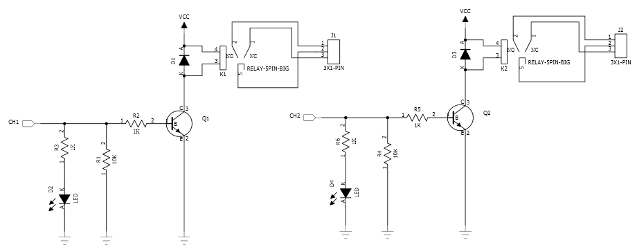
Here is a circuit diagram for two of the relays on the relay module (CH1 and CH2).
This was taken from the iteadstudio site.
The Video
