Posts with «serial communication» label

Biggest WiFiChron display so far

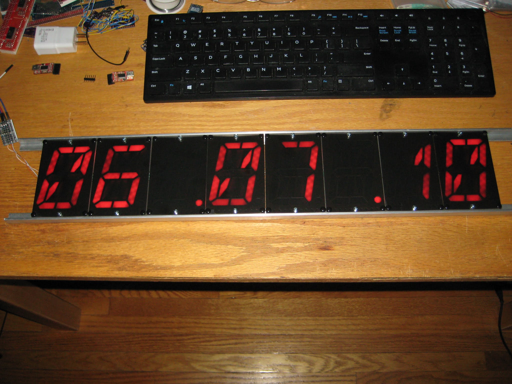
In the world of 16-segment displays, Klais-16 is the biggest I have seen, at about 8cm (3") character height. Multiple displays can be daisy-chained and controlled through serial communication (1 pin, TX). It is open source and available to buy on Tindie at the very reasonable price of US$15 a piece.

The biggest challenge was mechanical, particularly, finding a way to mount the 8 individual displays. Let me explain. I received the displays as ready-to-use (assembled, programmed and tested) products. I did  not expected to dis-assemble them (not even partially) in order to mount them. The two mounting methods described in the documentation (using 15mm and 20mm profiles, respectively) ask for just that, basically to cut the original plastic rivets and, eventually, to replace them with (your own) M3 screws when fixing them to the rails. (I actually started going along with either described method until I realized I did not want to open them up). The easiest solution I found in the end was to use 1/2" x 1/2" L-profile, as shown below. For this, I only cut the middle rivets and used the holes to screw each individual display to the rails.


The software support consists in adding one class, DisplaySoftSerial.cpp, shown below.

#include <Arduino.h>
#include <SoftwareSerial.h>
#include "DisplaySoftSerial.h"

SoftwareSerial ss(7, 2); // RX not used; TX=2;

//******************************************************************
//
void Display_t::setup()
{
ss.begin(19200);
}

//******************************************************************
// draw the 8 characters on the screen;
//
void Display_t::writeDisplay(char* displayBuffer)
{
char reverseBuffer[9] = {0};

for (byte i=0; i<9; i++)
{
reverseBuffer[i] = (displayBuffer[7-i]);
}
ss.write(reverseBuffer);
}

//*******************************************************************
// brightness level is number between 0 and 7, 0 being the brightest;
//
void Display_t::setBrightness(uint8_t brightness)
{
// cannot do;
}

//*******************************************************************
//
void Display_t::reset()
{
}


The Klais-16 display's baud rate can be selected in the range 4800 to 115200, through solder jumpers. The default (no soldering) is 115200. I set it to 19200 because:
  • SoftwareSerial library cannot handle 115200
  • only one solder bridge is required
As you can see from the code above, the brightness cannot be adjusted (or at least I am not aware). Maybe future versions will implement this feature.

The WiFiChron with the 8 Klais-16 displays consumes an average of 700mA (at 5V). The brightness is not amazing, probably because some of the light is absorbed by the top translucent PCB.
I think it can make a great clock for interiors (schools, hallways etc.), visible from at least 10 meters away.


Serial communication with arduino

In this post, we will learn how to serial communicate other device or arduino suing serial communication.

Introduction:

Serial communication (RS-232) is widely used communication for data transfer. It just uses three wires: Rx, Tx and GND

  In serial communication, 8/9 -bit is transferred through a single wire. The data frame is like this:

Start bit > Data fields (8 or 9 bit data) > Stop bit


Speed of data transfer is measured in terms of baud rate or bps:

Standard is: 9600 baud rate, none parity bit and one stop bit.
The baud rate should be same for both the devices. Any mismatch in the baud rate and the data will not be transmitted properly.
Bluetooth module (HC-05), Zigbee, GMS module, GPS module all these module uses serial communication. In fact, for communication between two microcontroller, we can use serial communication.

Connections:

Arduino                                                      Device
Tx            ===============>               Rx
Rx            ===============>               Tx
GND        ===============>               GND

For interfacing arduino with pc/ laptop, we need terminal software like bray's terminal. 

Just plug in the arduino in your pc/ laptop upload the program below and open terminal software.
Open comport in terminal sofware. The comport should be of arduino.

/* Program starts here */

void setup() {
Serial.begin(9600);   // starts serial communication @9600 bps
}

void loop() {
Serial.print("ARDUINO");   // serially print arduino
//Serial.println("ARDUINO");   // serially print arduino in new line

delay(1000);  // dealy of 1000ms
}

/* Program ends here */

Check this video:


Raspberry pi and Arduino serial communication

Hi, I have a problem with serial communication between Rasp and Arduino. I have written code for both. When I try serial communication on Rasp in Arduino IDE it is working. But when I try serial communication by code on Rasp, it is printing rectangles (in arduino serial monitor) and no what I send from rasp to arduino. So can anyone help me? :)

here is link to photo of arduino serial output https://www.dropbox.com/s/vjvd4p76mmu4ciq/rectangles.png?dl=0

read more

Serial vs I2C communication

Hi, please, can you tell me difference between I2C and Serial communication and which is the best for communication Raspberry Pi 2 with Arduino (T'Rex Controller). Thanks

Wise Clock 4 with remote "Alarm stop" button

The Ramos project brought the novel idea of a wireless alarm-stop button: instead of just reaching out to the press on the top of your nightstand alarm clock, you now have to actually get out of the bed and walk to a remote corner of your dwelling to click on a keypad. No chance you will return to sleep afterward :)

This remote alarm-stop feature for Wise Clock 4 can be implemented in several different ways, all of them using of the on-board XBee socket:
  • through a Bluetooth module;
  • through WiFi, using the Roving Networks WiFly module;
  • through XBee radios.
The cheapest and easiest would be the Bluetooth solution, providing that you already have a BT device (e.g. Android phone/tablet) to communicate with. In pseudo-code, it should look like this:

if (alarm is ON)
{
    while (Serial1.available())
    {
       read characters received;
       if (it is the expected string)
       {
            set alarm OFF;
        }
    }
}

The WiFi solution would require a second WiFi device (phone/tablet) to access a web site, or maybe they could talk directly (sockets), using their IP addresses.

The solution based on XBee relies on direct communication between two XBee radios. One would have to build the remote device, probably around an Arduino, with a keypad and an XBee.