Posts with «proteus» label

Serial communication with arduino

In this post, we will learn how to serial communicate other device or arduino suing serial communication.

Introduction:

Serial communication (RS-232) is widely used communication for data transfer. It just uses three wires: Rx, Tx and GND

  In serial communication, 8/9 -bit is transferred through a single wire. The data frame is like this:

Start bit > Data fields (8 or 9 bit data) > Stop bit


Speed of data transfer is measured in terms of baud rate or bps:

Standard is: 9600 baud rate, none parity bit and one stop bit.
The baud rate should be same for both the devices. Any mismatch in the baud rate and the data will not be transmitted properly.
Bluetooth module (HC-05), Zigbee, GMS module, GPS module all these module uses serial communication. In fact, for communication between two microcontroller, we can use serial communication.

Connections:

Arduino                                                      Device
Tx            ===============>               Rx
Rx            ===============>               Tx
GND        ===============>               GND

For interfacing arduino with pc/ laptop, we need terminal software like bray's terminal. 

Just plug in the arduino in your pc/ laptop upload the program below and open terminal software.
Open comport in terminal sofware. The comport should be of arduino.

/* Program starts here */

void setup() {
Serial.begin(9600);   // starts serial communication @9600 bps
}

void loop() {
Serial.print("ARDUINO");   // serially print arduino
//Serial.println("ARDUINO");   // serially print arduino in new line

delay(1000);  // dealy of 1000ms
}

/* Program ends here */

Check this video:


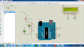
Arduino based DC Voltmeter (0-50 volts)

In this post, we are going to make digital voltmeter using arduino uno. It's a DC voltmeter and it's range is 0 to 50 volt. As we know, arduino is an open source hardware prototyping platform used worldwide by the hobbyists, educators and students across the globe.
This is a handy voltmeter.

Stuff required:

  1. Arduino uno
  2. 16*2 lcd
  3. 10k pot
  4. voltage source

Objective of the project: To make a digital voltmeter, which can measure voltage from 0 to 50 volt DC and thereafter it can display on 16*2 LCD.

Connections:

Make the connections as given in the figure below:

Arduino based voltmeter
Once the connection is made, upload the source code.

/* Source code */

const int volt=A0;

float val=0.0;

#include <LiquidCrystal.h>

LiquidCrystal lcd(12, 11, 5, 4, 3, 2);

void setup() {
  lcd.begin(16, 2);
  lcd.print("VOLTMETER");
}

void loop() {
  val=analogRead(volt);
  val=val*4.887;     // convert digital count into millivolt
  val=val/1000;      // convert millivolt into volts
  val=val*10.0;
  lcd.setCursor(0, 1);
  lcd.print(val);
}

/* End of source code */

Check out the video:


Hope you guys have enjoyed the post.

Thanks for reading the post.

Simulating arduino uno in proteus

By default, proteus don't have any library for arduino.

First of all, install library for proteus using the previous post Arduino library

Now, one problem arises how to get hex file of our program.

It lies in the following directory:
C:\Users\ \AppData\Local\Temp

You can make a shortcut of temp folder on your desktop to easily access it. By default, temp folder is hidden you have to unhide it.

This picture will make it simple

File directory
In proteus, double click on arduino uno. It will pop-up a window named edit component on program file click on browse icon to browse your hex file.
Browsing hex file
Always double the time and date of your hex file to ensure that are using correct file.

Thanks for giving your valuable time.

Stay tuned for more updates !!


Interfacing lcd with arduino

How to interaface lcd (4-bit interface) with arduino?

In this tutorial, we are going to discuss , how to interface lcd with arduino.

We are using 16*2 lcd, means it have two rows and 16 columns. Overall, we can display 32 characters.

16*2 LCD

Lcd have 16 pins, out of which six are connected to arduino. D4-D7 are data pins. RS, RW and EN pins are also there. RW pin is permanently grounded since we are writing to lcd.
Pin no 3 is connected to pot (10k) in order to change the contrast. Pin no 15 and 16 are for backlight.
Since lcd don't have any backlight.

Code:

// include the library code:
#include <LiquidCrystal.h>

// initialize the library with the numbers of the interface pins
LiquidCrystal lcd(12, 11, 5, 4, 3, 2);

void setup() {
  // set up the LCD's number of columns and rows:
  lcd.begin(16, 2);
  // Print a message to the LCD.
  lcd.print("hello, world!");
}

void loop() {
  // set the cursor to column 0, line 1
  // (note: line 1 is the second row, since counting begins with 0):
  lcd.setCursor(0, 1);
  // print the number of seconds since reset:
  lcd.print(millis() / 1000);
}

Simulation in proteus
Hope, you had enjoyed the tutorial.

Stay tuned for more updates !!

How to add library to proteus

In this post, we are going to discuss how to place library in proteus. As we all know that, there is no library of many components/ devices in arduino. We can add external libraries to proteus either provided by third party or written by an individual.

Basically, library consists of two files having extension .IDX and .LIB

We have to place these two files in the following directory:

C:\Program Files (x86)\Labcenter Electronics\Proteus 7 Professional\LIBRARY

If you are using 32-bit windows, then you to place  file in Program Files. As there is no Program Files(x86) in 32-bit windows.

Download arduino library from the link given below:

Download from here:

Now extract this rar file. You have to place only arduino.idx and arduino.lib in library folder.

Proteus
Hope, you will enjoy the tutorial.

Stay tuned for more updates..
FunWithElectronics 06 Apr 13:10
arduino  library  proteus