Posts with «rants» label

Surgery on the Arduino IDE Makes Bigger Serial Buffers

It is pretty well-known that I’m not a big fan of the Arduino infrastructure. Granted, these days you have more options with the pro IDE and Platform IO, for example. But the original IDE always gives me heartburn. I realized just how much heartburn the other day when I wanted to something very simple: increase the receive buffer on an ATmega32 serial port. The solution I arrived at might help you do some other things, so even if you don’t need that exact feature, you still might find it useful to see what I did.
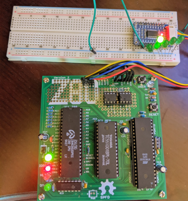
Following this experience I am genuinely torn. On the one hand, I despise the lackluster editor for hiding too much detail from me and providing little in the way of useful tools. On the other hand, I was impressed with how extensible it was if you can dig out the details of how it works internally.

First, you might wonder why I use the IDE. The short answer is I don’t. But when you produce things for other people to use, you almost can’t ignore it. No matter how you craft your personal environment, the minute your code hits the Internet, someone will try to use it in the IDE. A while back I’d written about the $4 Z80 computer by [Just4Fun]. I rarely have time to build things I write about, but I really wanted to try this little computer. The parts sat partially assembled for a while and then a PCB came out for it. I got the PCB and — you guessed it — it sat some more, partially assembled. But I finally found time to finish it and had CP/M booted up.

The only problem was there were not many good options for transferring data back and forth to the PC. It looked like the best bet was to do Intel hex files and transfer them copy and paste across the terminal. I wanted better, and that sent me down a Saturday morning rabbit hole. What I ended up with is a way to make your own menus in the Arduino IDE to set compiler options based on the target hardware for the project. It’s a trick worth knowing as it will come in handy beyond this single problem.

The Issue: Arduino Serial Buffer Size Limit

I won’t bore you with the details about getting the board to work since you will only care if you have one. Details are available in a discussion on Hackaday.io, if you really want to follow it. But the upshot was that for XModem transfers, [Just4Fun] felt like the default Arduino serial buffer wasn’t big enough to be reliable. It did seem to work with the default 64-byte buffer, but XModem sends more data than that and it would be easy to imagine it getting overrun.

How hard can it be to update the buffer? In one way, it is trivial. In another way, it is very difficult because the tools want to help you so badly.

Tool Chain

The little computer project uses a real Z80 chip and uses an ATMega32A for almost all the support functions. It generates the clock, acts like a serial port, acts like a disk drive, and so on. However, the ATMega32 doesn’t directly have Arduino IDE support so you have to install a toolchain for it. The project called for MightyCore so that’s what I used.

The libraries for hardware serial were all set up using #define statements to allow you to adjust the buffer sizes. By default, if you haven’t set up anything, you get a default based on the amount of RAM your processor provides:


#if !defined(SERIAL_TX_BUFFER_SIZE)
#if ((RAMEND - RAMSTART) < 1023)
#define SERIAL_TX_BUFFER_SIZE 16
#else
#define SERIAL_TX_BUFFER_SIZE 64
#endif
#endif
#if !defined(SERIAL_RX_BUFFER_SIZE)
#if ((RAMEND - RAMSTART) < 1023)
#define SERIAL_RX_BUFFER_SIZE 16
#else
#define SERIAL_RX_BUFFER_SIZE 64
#endif
#endif

Making the Change

So this is easy, right? Just define those symbols before HardwareSerial.h loads. Uh oh. That file is loaded by Arduino.h. The IDE wants to add that to your program and it forces it to be first. There seems to be some IDE versions that check if you already included it so they don’t include it twice, but version 1.8.5 didn’t seem to do that. Maybe I can add some options in the preferences to pass to the compiler. Nope. Not via the IDE, anyway.

Not that I didn’t try a lot of things. It was tempting, of course, to simply change the core libraries. But that’s bad. You might want the defaults later. If you update the tool chain, you’ll lose your updates. I wanted to avoid that. Some people on the Internet suggested making a copy of the platform files and modifying those. Still not ideal.

Test Your Assumptions With Custom Error Reporting

I could tell things I tried were not working because I would put #if statements and #error statements temporarily in HardwareSerial.cpp. For example:

#if SERIAL_RX_BUFFER_SIZE==256
#error 256
#endif

Now if a compile causes an error 256, I know I was able to set the size. If not, then the system was resisting my changes.

Compromise: Adding Menu Options At the Board Level

I really wanted a way to make a change just in my project and set the serial buffer sizes. I failed at that. What I did do was make a modification to the boards.txt provided by Mighty Core. Yes, I will have to watch for upgrades overwriting my changes, but they are simple and it will be obvious that it is missing.

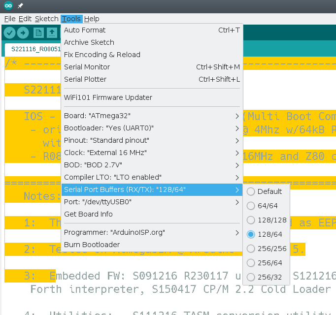
The reason it will be obvious is that I created a menu for the IDE that only appears when using ATMega32 for Mighty Core. This menu lets you select a few preset buffer sizes.

There were three parts to making this work:

  1. You have to tell the IDE you have a menu item and what it looks like.
  2. The new item needs to set some compiler options.
  3. Because the existing system also sets some compiler options, you have to make sure not to clobber them.

The first part is easy. The boards.txt file was (for me) in ~/.arduino15/packages/MightyCore/hardware/avr/2.0.5/boards.txt. Near the top there’s a list of menu keys and I added mine to the end:


# Menu options
menu.clock=Clock
menu.BOD=BOD
menu.LTO=Compiler LTO
menu.variant=Variant
menu.pinout=Pinout
menu.bootloader=Bootloader
menu.SerialBuf=Serial Port Buffers (RX/TX)

Next, I moved down the file and added my menu before the existing LTO menu option for the ATMega32:


32.menu.SerialBuf.disabled=Default
32.menu.SerialBuf.disabled.compilerSB.c.extra_flags=
32.menu.SerialBuf.disabled.compilerSB.cpp.extra_flags=

32.menu.SerialBuf.SB64=64/64
32.menu.SerialBuf.SB64.compilerSB.c.extra_flags=-DSERIAL_RX_BUFFER_SIZE=64 -DSERIAL_TX_BUFFER_SIZE=64
32.menu.SerialBuf.SB64.compilerSB.cpp.extra_flags=-DSERIAL_RX_BUFFER_SIZE=64 -DSERIAL_TX_BUFFER_SIZE=64

32.menu.SerialBuf.SB128=128/128
32.menu.SerialBuf.SB128.compilerSB.c.extra_flags=-DSERIAL_RX_BUFFER_SIZE=128 -DSERIAL_TX_BUFFER_SIZE=128
32.menu.SerialBuf.SB128.compilerSB.cpp.extra_flags=-DSERIAL_RX_BUFFER_SIZE=128 -DSERIAL_TX_BUFFER_SIZE=128

32.menu.SerialBuf.SB12864=128/64
32.menu.SerialBuf.SB12864.compilerSB.c.extra_flags=-DSERIAL_RX_BUFFER_SIZE=128 -DSERIAL_TX_BUFFER_SIZE=64
32.menu.SerialBuf.SB12864.compilerSB.cpp.extra_flags=-DSERIAL_RX_BUFFER_SIZE=128 -DSERIAL_TX_BUFFER_SIZE=64

32.menu.SerialBuf.SB256=256/256
32.menu.SerialBuf.SB256.compilerSB.c.extra_flags=-DSERIAL_RX_BUFFER_SIZE=256 -DSERIAL_TX_BUFFER_SIZE=256
32.menu.SerialBuf.SB256.compilerSB.cpp.extra_flags=-DSERIAL_RX_BUFFER_SIZE=256 -DSERIAL_TX_BUFFER_SIZE=256

32.menu.SerialBuf.SB25664=256/64
32.menu.SerialBuf.SB25664.compilerSB.c.extra_flags=-DSERIAL_RX_BUFFER_SIZE=256 -DSERIAL_TX_BUFFER_SIZE=64
32.menu.SerialBuf.SB25664.compilerSB.cpp.extra_flags=-DSERIAL_RX_BUFFER_SIZE=256 -DSERIAL_TX_BUFFER_SIZE=64

32.menu.SerialBuf.SB25632=256/32
32.menu.SerialBuf.SB25632.compilerSB.c.extra_flags=-DSERIAL_RX_BUFFER_SIZE=256 -DSERIAL_TX_BUFFER_SIZE=32
32.menu.SerialBuf.SB25632.compilerSB.cpp.extra_flags=-DSERIAL_RX_BUFFER_SIZE=256 -DSERIAL_TX_BUFFER_SIZE=32

Menu Structure

You can see that the 32.menu object groups all the items together for this processor. The next part is our menu key (SerialBuf). After that is a unique key for each memory item. It is important that you don’t reuse these. So, for example, if you have two SB64 keys only one is going to work.

If you stop at that key and put an equal sign you can assign the menu item the text you want to display. For example “Default” or “64/64.” You can also extend the key with a property and that property will be set if the option is active.

So, for example, if you select 256/256 then the compilerSB.c.extra_flags property will get set. I made that name up, by the way, and you’ll see why in a minute.

Peaceful Coexistence

There is no property called compilerSB.c.extra_flags. The correct property is compiler.c.extra_flags. However, the Mighty Core LTO option uses the same key. That’s why it was important that the new menu appears first and also that it sets a fake property. Then the LTO code needs a slight modification:


# Compiler link time optimization
32.menu.LTO.Os=LTO disabled
32.menu.LTO.Os.compiler.c.extra_flags={compilerSB.c.extra_flags}
32.menu.LTO.Os.compiler.c.elf.extra_flags=
32.menu.LTO.Os.compiler.cpp.extra_flags={compilerSB.cpp.extra_flags}
32.menu.LTO.Os.ltoarcmd=avr-ar

32.menu.LTO.Os_flto=LTO enabled
32.menu.LTO.Os_flto.compiler.c.extra_flags={compilerSB.c.extra_flags} -Wextra -flto -g
32.menu.LTO.Os_flto.compiler.c.elf.extra_flags=-w -flto -g
32.menu.LTO.Os_flto.compiler.cpp.extra_flags={compilerSB.cpp.extra_flags} -Wextra -flto -g
32.menu.LTO.Os_flto.ltoarcmd=avr-gcc-ar

The big change is that each set of flags adds to whatever the new menu set in its custom property. This way, all the flags get put into the correct property, compiler.c.extra_flags.

I set up error traps to catch all the cases to make sure they were being set right. In addition, after removing those traps, I could see my memory usage go up accordingly.

Customize

Of course, you can modify the parameters if you want something different. You could also use this trick to set other parameters before the Arduino.h file takes over. There’s some documentation about how to set up the platform definitions, including boards.txt.

It would have probably been better for me to make a custom boards.txt file with the same information in it but then I’d need to take the rest of Mighty Core with me. Instead, I just keep a copy of the file called boards.txt.custom and if my menu disappears, I just have to compare that file with the boards.txt file to see what changed.

Of course, if you don’t have to support people using the IDE, maybe just give it up. The Pro IDE is better, even if it does have some shortcomings. Plus there’s always Platform.io.

My Life in the Connector Zoo

“The great thing about standards is that there are so many to choose from.” Truer words were never spoken, and this goes double for the hobbyist world of hardware hacking. It seems that every module, every company, and every individual hacker has a favorite way of putting the same pins in a row.

We have an entire drawer full of adapters that just go from one pinout to another, or one programmer to many different target boards. We’ll be the first to admit that it’s often our own darn fault — we decided to swap the reset and ground lines because it was convenient for one design, and now we have two adapters. But imagine a world where there was only a handful of distinct pinouts — that drawer would be only half full and many projects would simply snap together. “You may say I’m a dreamer…”

This article is about connectors and standards. We’ll try not to whine and complain, although we will editorialize. We’re going to work through some of the design tradeoffs and requirements, and maybe you’ll even find that there’s already a standard pinout that’s “close enough” for your next project. And if you’ve got a frequently used pinout or use case that we’ve missed, we encourage you to share the connector pinouts in the comments, along with its pros and cons. Let’s see if we can’t make sense of this mess.

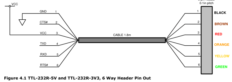
FTDI TTL Serial

The de-facto standard for a hacker’s TTL serial pinout is definitely the layout that FTDI uses for their USB/TTL serial cables. Said cable is just so handy to have on hand that you’d be silly to use any other pinout for the job. And the good news is that the rest of the world has basically joined in. From the Chinese “Pro Mini” cloneduinos to the Hackaday Edition Huzzah ESP8266 board, and from Adafruit’s FTDI Friend to Modern Device’s USB-BUB, almost everyone uses this pinout. A victory for the common man!

There is one slight point of contention, however, and that’s whether pin 6 is DTR or RTS#. We never use either, so we couldn’t care less, but if you’re counting on your programmer sending the DTR signal to enter programming mode on the device (we’re looking at you Arduino!) then you’ll want DTR on pin 6, and the original FTDI cable, ironically, has the “wrong” pinout. Perhaps that’s why Sparkfun avoided the whole debacle and went their own way, breaking out every signal off the FTDI chip into their own unique configuration.

If you’re only going to break out TTL serial lines, you’d be a fool to use any other pinout.

Modules and Other Communications

Unlike the case with simple serial, connecting various kinds of modules to mainboards is a difficult problem. Creating a single pinout or connector specification for many potential protocols or arbitrary signals is a Herculean task. Surprisingly, it’s been done a few times over. Here are some notables.

Pmod

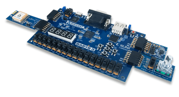
Digilent makes a wide range of FPGA demo boards, and they needed an in-house standard pinout that they could use to plug into various add-on peripheral modules that they sell. Thus Pmod was born. It has since become a full-fledged, and trademarked, open standard that you can use in your designs. Here’s the PDF version of the specification for you to print out, so you know they mean business.

There are a few aspects of Pmod that we think are particularly clever. First, the number of pins involved is “just right” at six, and it’s easily expandable. They use standard 0.1″ pitch pins and headers. Two lines carry power and ground, leaving four free pins for SPI, UART, or whatever else. The specification is that all power and signal voltages are 3.3 V because they’re designed for FPGAs after all. You can mix and match if you know what you’re doing, but they won’t let you call it Pmod(tm).

Eric Brombaugh’s iceRadio FPGA SDR, plugged together with Pmods

If you need more than four signals, there’s a twelve-pin version which is just two six-pin Pmods stacked into a double-row header. The extra power and ground are redundant, but it makes a twelve-pin output very flexible, because nothing stops it from being used as two sixes. The standard also says that the twelve-pin headers are to be spaced at 0.9″ center-to-center, so you can even connect two of them together when you need sixteen board-to-board signal connections. We like the modularity and expandability.

Pmod connectors are multi-protocol, but for each protocol there is a single pinout. So there’s an SPI Pmod and an I2C Pmod, and the pins are always in the same place. There isn’t a Pmod standard for every conceivable application, of course, so there’s a GPIO pinout that gives you free rein over what goes where. We think that it would be nice if some additional notable protocols (I2S? one-wire? servos? analog stereo audio?) were included in the specs, but the community can also handle these lower-level details.

In our eyes, Pmod is nearly perfect. It uses cheap hardware, is easily expandable, and the smallest incarnations are small enough to fit on all four sides of a one-inch-square board. If you’re willing to pay the brand-name premium, Digilent makes an incredible range of modules. We want to see more hackers outside of the FPGA scene get on it.

mikroBUS

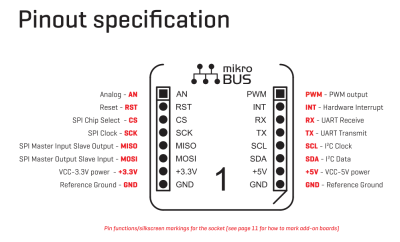
What Digilent is to development boards in the US, MikroElektronika is in Europe. While Pmod aims to be capable of doing anything, Mikro-E’s mikroBUS connector wants to do everything, which is to say it has I2C, SPI, UART, two voltages, and even a few extra signals all on the same pinout. Physically, it’s two single rows of eight pins, spaced 0.9″ apart side-to-side, which means it fits into a breadboard nicely. Here’s the spec in PDF.

The tradeoff here, relative to Pmod, is that a lot of pins go unused on any given design. With (only) one “analog” channel, you wouldn’t choose mikroBUS to send stereo audio, whereas nothing stops you from calling the Pmod’s GPIO lines analog and sending four channels of sound. But that mikroBUS gains is fool-proofness. (Well, they could have also made it asymmetric…) There’s no chance of a newbie plugging an SPI module in where an I2C module is expected and scratching their heads. With mikroBus, it should just work.

Microchip has added a mikroBus port to their Curiosity boards, and MikroElektronika makes a ton of modules. If your audience consists of beginners, and one footprint for all protocols, it’s worth considering.

Seeed’s Grove

Meanwhile in China, Seeed Studios makes open-source modules, and makes them cheap. Their Grove connector uses only four pins, with power and ground among them. The have standard pinouts for UART, I2C, and for servo motors. Sensors and other analog peripherals are allocated one “primary” pin and one “secondary” and it’s assumed that you know what you’re doing. The idea behind their system is that you add a shield to your microcontroller board, and they break out the relevant pins into these four-pin Grove headers.

This is great for small things and I2C devices, which is Seeed’s catalog, but there just aren’t enough signal pins to run SPI or an analog RGB LED, for instance. But because of the small number of pins, they use very inexpensive polarized cables and shrouds that you can’t plug in the wrong way, and that take up relatively little board space. That’s Grove’s design trade-off.

Servo Motor control

One of these things is not like the others…

Hobby servo motors need three wires: voltage, ground, and a signal to tell them where to point. There are three distinct ways to arrange these wires, but Futaba, HiTec, Tower, GWS, and JR servos all chose to put them in SVG (or GVS) order, and there’s no reason to buck the trend. (Airtronics, what were you thinking?!)

SVG is also a handy pinout to use for all sorts of one-signal sensors or actuators where space is a premium, and we’ve seen this in a few designs (here and here, for instance). But we’re torn. Relative to the Grove, for instance, you’re just saving one pin. Even the Pmod would work with only three pins’ overhead. Is that worth complicating your life with another pinout? If you need a lot of powered one-signal devices, or servos, it probably is, and you can hardly beat SVG or GVS, whichever way you look at it.

Arduino

Viewed in the light of any of the other module interconnection systems, the Arduino is the worst of all worlds. It’s monolithic like mikroBUS, but it’s gigantic — you have to build a 55×73 mm board and accommodate 30 pins and pass-throughs if you’d like it to be stackable. The pins have a funny spacing (that gap!), that doesn’t fit any normal protoboard. Nobody goes through the trouble of building a shield just for an I2C connection. No wonder most Arduino projects look like a breadboard hedgehog. About the only good thing we can say about it is that it’s hard to plug one in backwards.

There’s also the tiny little factor that there’s a million Arduino shields out there, a huge community built around them, and widespread support for them. Which turns out to trump all of the reasonable design concerns. (Shakes head.)

Miscellany

Of course, there are other very specific pinouts that one might encounter, like the old ESP-01 module, or the XBee, or the nRF24. Adapting modules to fit boards is always going to be a pain, because the manufacturers will pick whatever suits them on that day. Programmer pinouts for specific microcontrollers are a similar story, as is JTAG, which is a beautiful standard with a dogs’ breakfast of pinout possibilities. (We could do a whole column!)

Faced with this inevitability, and the need for many one-off adapters, what can you do? What we do is buy a lot of those cheap “Dupont” female-to-female cables, get the connections working and tested, and then tape them permanently together and label them. It’s not as pretty as a dedicated PCB adapter, but it’s quick and easy and gets you moving on to what you wanted to do in the first place.

Wrapup and Recommendations

The goal of connectors, and their standards, is putting parts together. If you’re designing a sensor module with more than a couple components, and you want it to be maximally easy for yourself and others to hook up to whatever mainboard they’ve got, this is no easy task. The end result is a proliferation of translators, adapter boards, hats, shields, capes, or whatever else. We have a drawer and a half full, and we bet you do too.

Yes, I do see what I’m suggesting here. [source: xkcd 927]
We’d be happy to see the world settle on Pmod for most needs, honestly, and we’d even throw away our beloved FTDI serial pinout in the name of standardization (or make an adapter). We can also see the need for exceptions like SVG / servo connectors when small sensors or multiples are in play. There will always be the need for dedicated on-board connectors as well, of course. Nobody said hardware was easy.

What’s your solution to the ultimate connector conundrum? Are there important connector systems that we’ve left out? What are their design tradeoffs? How stoked would you be if things could just plug together? Let us know!

Thumbnail image courtesy of [Raspberry Pi Controller].


Filed under: Engineering, Hackaday Columns, hardware, rants

Ask Hackaday: Arduino in Consumer Products

Speak with those who consider themselves hardcore engineers and you might hear “Arduinos are for noobs” or some other similar nonsense. These naysayers see the platform as a simplified, overpriced, and over-hyped tool that lets you blink a few LEDs or maybe even read a sensor or two. They might say that Arduino is great for high school projects and EE wannabes tinkering in their garage, but REAL engineering is done with ARM, x86 or PICs. Guess what? There are Arduino compatible boards built around all three of those architectures. Below you can see but three examples in the DUE, Galileo, and Fubarino SD boards.

This attitude towards Arduino exists mainly out of ignorance. So let’s break down a few myths and preconceived biases that might still be lurking amongst some EEs and then talk about Arduino’s ability to move past the makers.

Arduino is NOT the Uno

When some hear “Arduino”, they think of that little blue board that you can plug a 9v battery into and start making stuff. While this is technically true, there’s a lot more to it than that.

  1. An Arduino Uno is justanAVR development board.AVRs are similar to PICs. When someones says “I used a PIC as the main processor”, does that mean they stuck the entire PIC development board into their project? Of course not. It’s the same with Arduino (in most cases), and design is done the same way as with any other microcontroller –
    • Use the development board to make, create and debug.
    • When ready, move the processor to your dedicated board.
  2. What makes an Arduino an “Arduino” and not justan AVR but the bootloader. Thus:
    • An Atmega328P is an AVR processor.
    • An Atmega328P with the Arduino bootloader is an Arduino.
  3. The bootloader allows you to program the AVR with the Arduino IDE. If you remove the bootloader from the AVR, you now have an AVR development board that can be programmed with AVR Studio using your preferred language.

There Is No Special Arduino Language

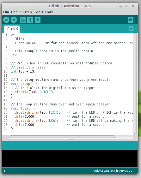
Arduino “blink” sketch should run on any Arduino compatible board.

Yes, I know they call them sketches, which is silly. But the fact is it’s just c++. The same c++ you’d use to program your PIC. The bootloader allows the IDE to call functions, making it easy to code and giving Arduino its reputation of being easy to work with. But don’t let the “easy” fool you. They’re real c/c++ functions that get passed to a real c/c++ compiler. In fact, any c/c++ construct will work in the Arduino IDE. With that said – if there is any negative attribute to Arduino, it is the IDE. It’s simple and there is no debugger.

The strength comes in the standardization of the platform. You can adapt the Arduino standard to a board you have made and that adaptation should allow the myriad of libraries for Arduino to work with your new piece of hardware. This is a powerful benefit of the ecosystem. At the same time, this easy of getting things up and running has resulted in a lot of the negative associations discussed previously.

So there you have it. Arduino is no different from any other microcontroller, and is fully capable of being used in consumer products along side PICs, ARMs etc. To say otherwise is foolish.

What is the Virtue of Arduino in Consumer Products?

This is Ask Hackaday so you know there’s a question in the works. What is the virtue of Arduino in consumer products? Most electronics these days have a Device Firmware Upgrade (DFU) mode that allows the end user to upgrade the code, so Arduino doesn’t have a leg up there. One might argue that using Arduino means the code is Open Source and therefore ripe for community improvements but closed-source binaries can still be distributed for the platform. Yet there are many products out there that have managed to unlock the “community multiplier” that comes from releasing the code and inviting improvements.

What do you think the benefits of building consumer goods around Arduino are, what will the future look like, and how will we get there? Leave your thoughts below!


Filed under: Arduino Hacks, Ask Hackaday, Hackaday Columns, rants