Posts with «light» label

Don’t Take Photos of Your Arduino 101 Either, Its Light Sensitive

Wafer level chips are cheap and very tiny, but as [Kevin Darrah] shows, vulnerable to bright light without the protective plastic casings standard on other chip packages.

We covered a similar phenomenon when the Raspberry Pi 2 came out. A user was taking photos of his Pi to document a project. Whenever his camera flash went off, it would reset the board.

[Kevin] got a new Arduino 101 board into his lab. The board has a processor from Intel, an accelerometer, and Bluetooth Low Energy out of the box while staying within the same relative price bracket as the Atmel versions. He was admiring the board, when he noticed that one of the components glittered under the light. Curious, he pulled open the schematic for the board, and found that it was the chip that switched power between the barrel jack and the USB. Not only that, it was a wafer level package.

So, he got out his camera and a laser. Sure enough, both would cause the power to drop off for as long as the package was exposed to the strong light. The Raspberry Pi foundation later wrote about this phenomenon in more detail. They say it won’t affect normal use, but if you’re going to expose your device to high energy light, simply put it inside a case or cover the chip with tape, Sugru, or a non-conductive paint to shield it.


Filed under: Arduino Hacks
Hack a Day 06 May 00:01

UV Laser Projector Shines With Glow-in-the-Dark Vinyl

Mirror galvanometers were originally developed in the 17th century to precisely measure very small changes in current. Unlike other instruments of the day, a mirror galvanometer could clearly show minute current variations by translating tiny movements of the mirror into large movements of the light reflected off of the mirror. Before clean electrical amplification became possible, this was the best means of measuring tiny differences in current. True mirror galvanometers are very sensitive instruments, but hobby servos can be used as a low-fidelity alternative, like with this project on Hackaday.io created by [robives].

Using a mirror galvanometer is by far the most common technique for laser projection shows – it’s really the only way to move the laser’s beam quickly enough to create the visual illusion of a solid line in real time. A mirror galvanometer works by using coils to attract magnets attached to the mirror, allowing the angle of the mirror to change when current is applied to the coils. This movement is extremely small, but is amplified by the distance to the projection surface, meaning the laser’s beam can move huge distances in an instance. If you’ve ever seen a laser show, it almost certainly used this technique. But driving galvos requires a beefy DAC, so we can’t blame [robives] for wanting to keep it digital.

[robives’s] project side-steps the need for galvanometers by using glow-in-the-dark vinyl and a UV laser. The result is a laser beam trail which lasts much longer, which means that solid lines are visible without the need for high-speed galvos. A build like this lets you experiment with laser projections without dealing with sensitive mirror galvos, and instead use components that you probably already have sitting on your workbench.


Filed under: laser hacks
Hack a Day 02 Dec 03:00

Arduino LED Light Box

Description

Long straight lines of LED luminescence is nice, but sometimes you may want to light up something that has an unusual shape, or is not so linear. This is where the 12mm diffused flat digital RGB LED Pixels can come into play. This cool strand of 25 NeoPixels fit nicely into 12mm pre-drilled holes of any material you like.

This tutorial is dedicated to making a LED Light Box. I wanted the box to be equally as interesting during the day as it was at night. If you decide you make your own, feel free to be as creative as you want !! However, if you lack artistic acumen, you may need to source a minion or two.


Arduino Libraries and IDE

Before you start to hook up any components, upload the following sketch to the Arduino microcontroller. I am assuming that you already have the Arduino IDE installed on your computer. If not, the IDE can be downloaded from here.

The FastLED library is useful for simplifying the code for programming the NeoPixels. The latest "FastLED library" can be downloaded from here. I used FastLED library version 3.0.3 in this project.

If you have a different LED strip or your NeoPixels have a different chipset, make sure to change the relevant lines of code to accomodate your hardware. I would suggest you try out a few of the FastLED library examples before using the code below, so that you become more familiar with the library, and will be better equipped to make the necessary changes.

If you have a single strand of 25 Neopixels with the WS8201 chipset, then you will not have to make any modification below.


ARDUINO CODE:

Arduino Code Description

The code above will generate a randomised raindrop pattern on the NeoPixel LED Light box, however I have written code for a few more LED animations. These animations were written specifically for this light-box setup. In other words, once you have hooked everything up, you will be able to upload these other LED animations to the Arduino board without any further modification to the hardware/wiring, and yet experience a totally different light effect. You can find the code for the other animation effects by clicking on the links below:

  1. Breathing effect
  2. Ripple effect
  3. Clock effect
  4. Rotation effect
  5. Sweep effect
  6. Spiral effect
  7. Lightning effect
  8. Paparazzi in the Rain effect

Hooking it up:

Power requirements

Each Neopixel LED can draw up to 60 milliamps at maximum brightness (white). ie. 20 mA for each colour (red, green and blue). Therefore you should not try to power the LED strand directly from the Arduino, because the strand will draw too much current and damage the microcontroller(and possibly your USB port too). The LED strand will therefore need to be powered by a separate power supply. The power supply must supply the correct voltage (5V DC) and must also be able to supply sufficient current (1.5A or greater per strand of 25 LEDs).

Excessive voltage will damage or destroy your Neopixel strand. The LEDs will only draw as much current as they need, however your power supply must provide at least 1.5A or greater for each strand. If you chain two strands together, you will need a 5V 3A power supply.

Neopixel strand connection

There are 25 Neopixel LEDs per strand. Four of the wires at each end of the strand are terminated with a JST connector. The red wire is for power (VCC), blue wire for ground (GND), yellow wire is for Data, and green wire for Clock. A spare red wire (VCC) and a spare blue wire (GND) are attached to the ends of each strand for convenience, however, I did not use either. Please double check the colour of your wires... they may be different.

If you want to attach the LED strand to a breadboard, you can cut the JST connector off and use the Neopixel strand wires. Alternatively, if you would prefer to preserve the JST connector, you can simply insert jumper wires (or some male header pins) into the JST connector, and then plug them into the breadboard as required.

Each neopixel LED is individually controllable using two pins on your Arduino. The strand is directional. i.e. There is an INPUT side and an OUTPUT side. The strand should be connected such that wires from the microcontroller are attached to the INPUT side of the first neopixel. The arrows on each LED show the direction of data flow from INPUT to OUTPUT. The arrow on the first NeoPixel should be pointing towards the second NeoPixel, NOT towards the breadboard.

Other considerations

As a precaution, you should use a large capacitor across the + and - terminals of the power supply to prevent the initial onrush of current from damaging the Neopixels. I used a 4700uF 16V Electrolytic capacitor for this purpose. According to Adafruit, a 1000uF 6.3V capacitor (or higher) will also do the trick. You may also want to consider a 330 ohm resistor between the Arduino Digital pin and the strand's DATA pin.

If you want to power the Arduino using the regulated 5V external power supply. Disconnect the USB cable from the Arduino, and then connect the positive terminal of the power supply to the 5V pin on the Arduino. Be warned however, that excess voltage at this pin could damage your Arduino, because the 5V regulator will be bypassed.
 
Providing the USB cable is NOT connected to the Arduino, it should now be safe to plug the power supply into the wall. This setup will allow you to power the Neopixel strand and the Arduino using the same power supply.
 
WARNING: Never change any connections while the circuit is powered.

For more information about these NeoPixel strands, you may want to visit the Adafruit site. Adafruit was the source for most of these NeoPixel Strand precautions.


Fritzing diagram

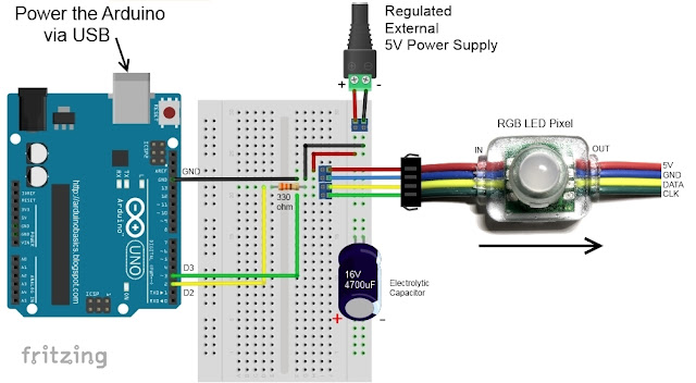
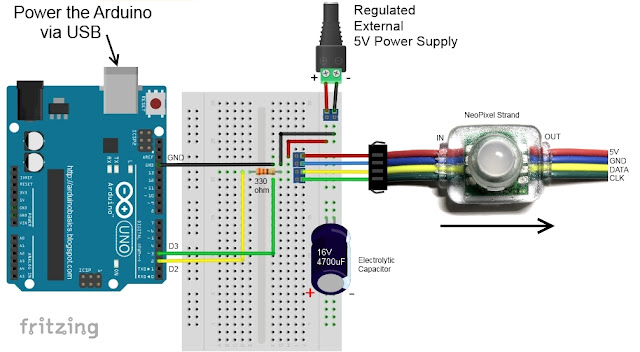
The following diagram demonstrates how to connect the NeoPixel Strand to the Arduino and to the External 5V power supply.


This diagram was created using Fritzing


Connection Instructions

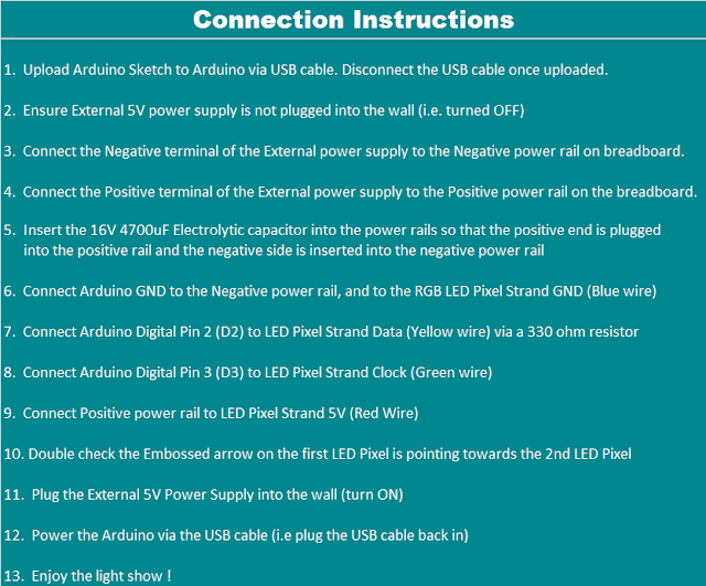
These instructions will help to guide you through the process of connecting your NeoPixel strand to the Arduino, and to the external power supply. The instructions assume that you will be powering the Arduino via a USB cable.


LightBox assembly

You will need to drill a 12mm hole into the craft timber box for each LED on the strand. It is worth taking the time to make accurate measurements before drilling the holes.
 
I made 12 holes for the outside circle pattern (12cm diameter), 6 holes for the inside circle pattern (8cm diameter), and a hole in the centre. I also made two holes at the front of the box, two on the left side, and two on the right side. I made one last hole at the back of the box for the 2.1mm DC power line socket.
 
Therefore you should have a total of 26 holes in the box. 25 of the holes are for the Neopixel LEDs and one for the external power supply socket.

The lid of the box is about 19.5cm x 14.5cm long, which makes for a very tight squeeze. Probably too tight, because you have to account for the inner dimensions of the box. The inside of the box is used to house the Arduino, breadboard, the chipset side of the LEDs and cables/components. The inner dimensions of the box are 18cm x 13cm. Therefore, the housing for the LED chipset PCB (1.8cm x 2.5cm) prevented the box from closing. I used a Dremel to carve out the space required to close the lid.

Each LED is approximately 8cm apart on the strand, however, if you are really keen, you could cut the wires and extend them to any distance you require. But keep in mind that each LED is mounted on a small PCB (with a WS2801 chipset).You will therefore need to leave a minimum of 2cm between each 12mm hole to accomodate the size of the PCB+LED. If you plan carefully, you can probably squeeze a couple of LEDs within a distance of 1cm... but I would recommend that you give yourself a bit more room, because the PCBs are not square, and there is a good chance that you will have to start all over again.

In hindsight, I could have made the circle patterns a bit smaller, however I don't know if I could have packed these LEDs any closer. The diameter of the inner circle pattern must be at least 2cm smaller than the outer circle pattern. So I think "a bigger box" would have been the best option.

Once all of the holes have been drilled, paint and decorate the box to suit your style.

When the paint is dry, insert the LEDs into the drilled holes in number order.
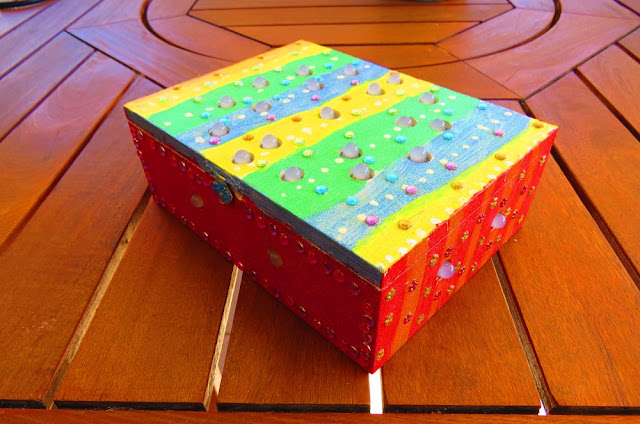
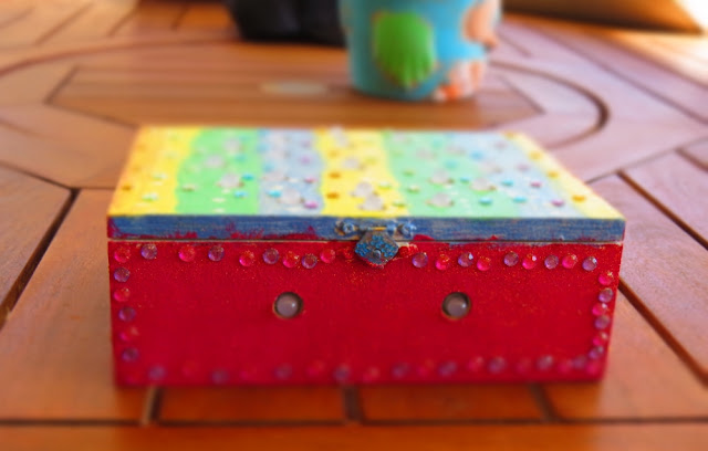
You can see the end result below.


Project Pictures

These pictures show the Light box after it has been drilled and painted. The LEDs have been inserted into their respective holes, and all wires + Arduino + breadboard are hidden within the box.


Concluding comments

Once you start writing LED animations for the NeoPixel Lightbox, it is very hard to stop. The colour combinations


If you like this page, please do me a favour and show your appreciation :

 
Visit my ArduinoBasics Google + page.
Follow me on Twitter by looking for ScottC @ArduinoBasics.
I can also be found on Pinterest and Instagram.
Have a look at my videos on my YouTube channel.


This project would not have been possible without OpenLab's collaborative effort.
Please visit their site for more cool projects.


However, if you do not have a google profile...
Feel free to share this page with your friends in any way you see fit.

Arduino LED Light Box

Description

Long straight lines of LED luminescence is nice, but sometimes you may want to light up something that has an unusual shape, or is not so linear. This is where the 12mm diffused flat digital RGB LED Pixels can come into play. This cool strand of 25 RGB LED pixels fit nicely into 12mm pre-drilled holes of any material you like.

This tutorial is dedicated to making a LED Light Box. I wanted the box to be equally as interesting during the day as it was at night. If you decide you make your own, feel free to be as creative as you want !! However, if you lack artistic acumen, you may need to source a minion or two.


Arduino Libraries and IDE

Before you start to hook up any components, upload the following sketch to the Arduino microcontroller. I am assuming that you already have the Arduino IDE installed on your computer. If not, the IDE can be downloaded from here.

The FastLED library is useful for simplifying the code for programming the RGB LED pixels. The latest "FastLED library" can be downloaded from here. I used FastLED library version 3.0.3 in this project.

If you have a different LED strip or your RGB LED pixels have a different chipset, make sure to change the relevant lines of code to accomodate your hardware. I would suggest you try out a few of the FastLED library examples before using the code below, so that you become more familiar with the library, and will be better equipped to make the necessary changes.

If you have a single strand of 25 RGB LED pixels with the WS8201 chipset, then you will not have to make any modification below.


ARDUINO CODE:

Arduino Code Description

The code above will generate a randomised raindrop pattern on the Arduino LED Light box, however I have written code for a few more LED animations. These animations were written specifically for this light-box setup. In other words, once you have hooked everything up, you will be able to upload these other LED animations to the Arduino board without any further modification to the hardware/wiring, and yet experience a totally different light effect. You can find the code for the other animation effects by clicking on the links below:

  1. Breathing effect
  2. Ripple effect
  3. Clock effect
  4. Rotation effect
  5. Sweep effect
  6. Spiral effect
  7. Lightning effect
  8. Paparazzi in the Rain effect

Hooking it up:

Power requirements

Each LED pixel can draw up to 60 milliamps at maximum brightness (white). ie. 20 mA for each colour (red, green and blue). Therefore you should not try to power the LED strand directly from the Arduino, because the strand will draw too much current and damage the microcontroller(and possibly your USB port too). The LED strand will therefore need to be powered by a separate power supply. The power supply must supply the correct voltage (5V DC) and must also be able to supply sufficient current (1.5A or greater per strand of 25 LEDs).

Excessive voltage will damage or destroy your LED pixel strand. The LEDs will only draw as much current as they need, however your power supply must provide at least 1.5A or greater for each strand. If you chain two strands together, you will need a 5V 3A power supply.

RGB LED pixel strand connection

There are 25 LED pixels per strand. Four of the wires at each end of the strand are terminated with a JST connector. The red wire is for power (VCC), blue wire for ground (GND), yellow wire is for Data, and green wire for Clock. A spare red wire (VCC) and a spare blue wire (GND) are attached to the ends of each strand for convenience, however, I did not use either. Please double check the colour of your wires... they may be different.

If you want to attach the LED strand to a breadboard, you can cut the JST connector off and use the LED pixel strand wires. Alternatively, if you would prefer to preserve the JST connector, you can simply insert jumper wires (or some male header pins) into the JST connector, and then plug them into the breadboard as required.

Each LED pixel is individually controllable using two pins on your Arduino. The strand is directional. i.e. There is an INPUT side and an OUTPUT side. The strand should be connected such that wires from the microcontroller are attached to the INPUT side of the first LED pixel. The arrows on each LED show the direction of data flow from INPUT to OUTPUT. The arrow on the first LED pixel should be pointing towards the second LED pixel, NOT towards the breadboard.

Other considerations

As a precaution, you should use a large capacitor across the + and - terminals of the power supply to prevent the initial onrush of current from damaging the RGB LED pixels. I used a 4700uF 16V Electrolytic capacitor for this purpose. According to Adafruit, a 1000uF 6.3V capacitor (or higher) will also do the trick. You may also want to consider a 330 ohm resistor between the Arduino Digital pin and the strand's DATA pin.

If you want to power the Arduino using the regulated 5V external power supply. Disconnect the USB cable from the Arduino, and then connect the positive terminal of the power supply to the 5V pin on the Arduino. Be warned however, that excess voltage at this pin could damage your Arduino, because the 5V regulator will be bypassed.
 
Providing the USB cable is NOT connected to the Arduino, it should now be safe to plug the power supply into the wall. This setup will allow you to power the RGB LED pixel strand and the Arduino using the same power supply.
 
WARNING: Never change any connections while the circuit is powered.

For more information about these RGB LED pixel strands, you may want to visit the Adafruit site. Adafruit was the source for most of these RGB LED pixel Strand precautions.


Fritzing diagram

The following diagram demonstrates how to connect the RGB LED pixel Strand to the Arduino and to the External 5V power supply.


This diagram was created using Fritzing


Connection Instructions

These instructions will help to guide you through the process of connecting your RGB LED pixel strand to the Arduino, and to the external power supply. The instructions assume that you will be powering the Arduino via a USB cable.


LightBox assembly

You will need to drill a 12mm hole into the craft timber box for each LED on the strand. It is worth taking the time to make accurate measurements before drilling the holes.
 
I made 12 holes for the outside circle pattern (12cm diameter), 6 holes for the inside circle pattern (8cm diameter), and a hole in the centre. I also made two holes at the front of the box, two on the left side, and two on the right side. I made one last hole at the back of the box for the 2.1mm DC power line socket.
 
Therefore you should have a total of 26 holes in the box. 25 of the holes are for the RGB LED pixel LEDs and one for the external power supply socket.
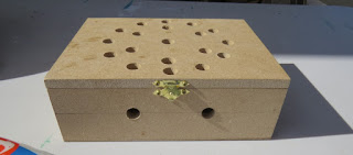
The lid of the box is about 19.5cm x 14.5cm long, which makes for a very tight squeeze. Probably too tight, because you have to account for the inner dimensions of the box. The inside of the box is used to house the Arduino, breadboard, the chipset side of the LEDs and cables/components. The inner dimensions of the box are 18cm x 13cm. Therefore, the housing for the LED chipset PCB (1.8cm x 2.5cm) prevented the box from closing. I used a Dremel to carve out the space required to close the lid.

Each LED is approximately 8cm apart on the strand, however, if you are really keen, you could cut the wires and extend them to any distance you require. But keep in mind that each LED is mounted on a small PCB (with a WS2801 chipset).You will therefore need to leave a minimum of 2cm between each 12mm hole to accomodate the size of the PCB+LED. If you plan carefully, you can probably squeeze a couple of LEDs within a distance of 1cm... but I would recommend that you give yourself a bit more room, because the PCBs are not square, and there is a good chance that you will have to start all over again.

In hindsight, I could have made the circle patterns a bit smaller, however I don't know if I could have packed these LEDs any closer. The diameter of the inner circle pattern must be at least 2cm smaller than the outer circle pattern. So I think "a bigger box" would have been the best option.

Once all of the holes have been drilled, paint and decorate the box to suit your style.

When the paint is dry, insert the LEDs into the drilled holes in number order.
You can see the end result below.


Project Pictures

These pictures show the Light box after it has been drilled and painted. The LEDs have been inserted into their respective holes, and all wires + Arduino + breadboard are hidden within the box.




Concluding comments

Once you start writing LED animations for the RGB LED pixel Lightbox, it is very hard to stop. The colour combinations


If you like this page, please do me a favour and show your appreciation :

 
Visit my ArduinoBasics Google + page.
Follow me on Twitter by looking for ScottC @ArduinoBasics.
I can also be found on Pinterest and Instagram.
Have a look at my videos on my YouTube channel.


This project would not have been possible without OpenLab's collaborative effort.
Please visit their site for more cool projects.


However, if you do not have a google profile...
Feel free to share this page with your friends in any way you see fit.

Sleek Desk Lamp Changes Colors Based on Sun Position

[Connor] was working on a project for his college manufacturing class when he came up with the idea for this sleek desk lamp. As a college student, he’s not fond of having his papers glowing brightly in front of him at night. This lamp takes care of the problem by adjusting the color temperature based on the position of the sun. It also contains a capacities touch sensor to adjust the brightness without the need for buttons with moving parts.

The base is made from two sheets of aluminum and a bar of aluminum. These were cut and milled to the final shape. [Connor] found a nice DC barrel jack from Jameco that fits nicely with this design. The head of the lamp was made from another piece of aluminum bar stock. All of the aluminum pieces are held together with brass screws.

A slot was milled out of the bottom of the head-piece to make room for an LED strip and a piece of 1/8″ acrylic. This piece of acrylic acts as a light diffuser.  Another piece of acrylic was cut and added to the bottom of the base of the lamp. This makes for a nice glowing outline around the bottom that gives it an almost futuristic look.

The capacitive touch sensor is a pretty simple circuit. [Connor] used the Arduino capacitive touch sensor library to make his life a bit easier. The electronic circuit really only requires a single resistor between two Arduino pins. One of the pins is also attached to the aluminum body of the lamp. Now simply touching the lamp body allows [Connor] to adjust the brightness of the lamp.

[Connor] ended up using an Electric Imp to track the sun. The Imp uses the wunderground API to connect to the weather site and track the sun’s location. In the earlier parts of the day, the LED colors are cooler and have more blues. In the evening when the sun is setting or has already set, the lights turn more red and warm. This is easier on the eyes when you are hunched over your desk studying for your next exam. The end result is not only functional, but also looks like something you might find at that fancy gadget store in your local shopping mall.


Filed under: Arduino Hacks

Using an Arduino to Light a Grounded F-16

Arduino boards and military hardware don’t generally go together. For a piece of hardware that is no longer in use and will be on display, however, it makes a great method for lighting control. In this case, the lights go to an F-16, beautifully restored for the National Museum of […]

Read more on MAKE

MAKE » Arduino 08 Dec 12:47
arduino  f-16  light  

Global emotional light with Arduino

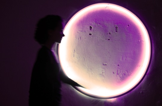
Based on open source technology and programming, LUZ is a lighting project that product designer Marina Mellado designed and targeted to those people who are physically and psychologically affected by the lack of sun or daylight.

Luz is a one meter diameter ring of light. It connects two LED stripes RGB SMD5050 to an Adafruit TCS34725 sensor ( which I use to get the temperature of colour (K) and the light intensity (Lux) Values ) and an Arduino Uno.

The electronic system is programmed to modify gradually the light-color sensibility of the lamp depending on the weather conditions when the sensor is positioned by the window.

Check the video below to see the lamp in action:

Arduino Blog 21 Nov 15:44

A simple light follower with Analog 180° Micro Servo

Servos are composed of an electric motor mechanically linked to a potentiometer and they are able to translate the width of the pulse into a position. When you command the servo  to rotate, the motor is powered until the potentiometer reaches the value corresponding to the commanded position.

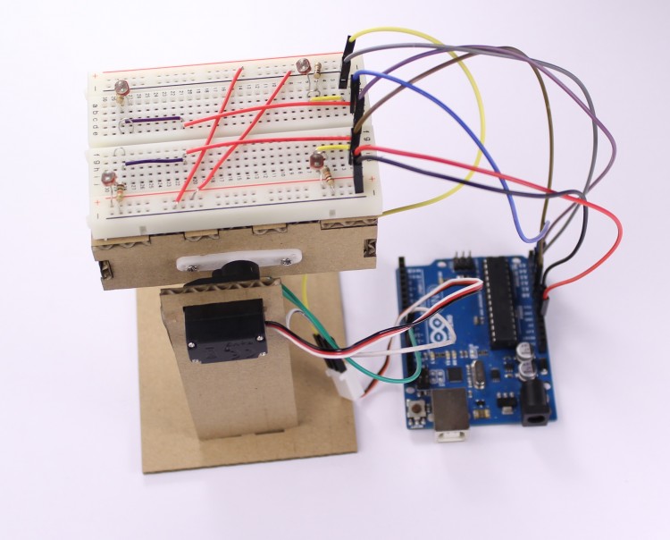
Today we’d like to share with you a tutorial with the aim of showing how to make a simple light follower made of cardboard using Arduino Uno and a microservo, in this case the Analog 180° Micro Servo.

Follow the step by step lesson to build one yourself.


Arduino Blog 10 Nov 22:18

433 MHz RF module with Arduino Tutorial 3


There are 4 parts to this tutorial:
To get the most out of this tutorial - it is best to start at tutorial Part 1, and then progress to Part 2 then Part 3 and then do Part 4 last. Doing the RF tutorials in this order will help you to understand the process better.


Project 3: RF Remote Control Emulation

In the first tutorial, I introduced the 433 MHz Transmitter and Receiver with a simple sketch to test their functionality. In the second tutorial, the 433MHz receiver was used to receive a signal from an RF remote. The RF remote signal was coded based on the pattern and length of its HIGH and LOW signals. The signals received by the remote can be described by the code below:

 
Code comparison table


The RF remote that I am using transmits the same signal 6 times in a row. The signal to turn the light on is different from that used to turn the light off. In tutorial 2, we were able to "listen to" or receive the signal from the RF remote using the RF receiver. I thought it would be possible to just play back the signal received on the Arduino's analogPin, but the time it takes to perform a digital write is different to the time it takes to do an AnalogRead. Therefore it won't work. You need to slow down the digitalWrite speed.
I would like to find out if it is possible to apply this delay to all 433 MHz signal projects, however, I only have one 433 MHz remote.

If the delay in your project is the same as mine (or different) I would be keen to know - please leave a comment at the end of the tutorial.

We are going to use trial and error to find the optimal digitalWrite delay time. We will do this by slowly incrementing the delay until the transmission is successful. The transmission is considered successful if the fan-light turns on/off. All we have to do is count the number of transmissions until it is successful, then we should be able to calculate the delay.


Parts Required


The Transmitter Fritzing Sketch


RF Calibration - Arduino Sketch


I used an array to hold the RF code for light ON and light OFF. Each number within the code represents a specific sequence of HIGH and LOW lengths. For example, 2 represents a SHORT HIGH and a LONG LOW combination. A short length = 3, a long length = 7, and a very long length = 92. You need to multiply this by the timeDelay variable to identify how much time to transmit the HIGH and LOW signals for.
The short and long lengths were identified from the experiments performed in tutorial 2 (using the RF receiver). Each code is transmitted 6 times. The LED is turned on at the beginning of each transmission, and then turned off at the end of the transmission. The timeDelay variable starts at 5 microseconds, and is incremented by 10 microseconds with every transmission.
In the video, you will notice that there is some flexibility in the timeDelay value. The Mercator Fan/Light will turn on and off when the timeDelay variable is anywhere between 75 and 135 microseconds in length. It also seems to transmit successfully when the timeDelay variable is 175 microseconds.
So in theory, if we want to transmit a signal to the fan/light, we should be able to use any value between 75 and 135, however in future projects, I think I will use a value of 105, which is right about the middle of the range.


Video


  Now that I have the timeDelay variable, I should be able to simplify the steps required to replicate a remote control RF signal. Maybe there is room for one more tutorial on this topic :)

Update: Here it is - tutorial 4
Where you can record and playback an RF signal (without using your computer).


433 MHz RF module with Arduino Tutorial 3


Project 3: RF Remote Control Emulation

In the first tutorial, I introduced the 433 MHz Transmitter and Receiver with a simple sketch to test their functionality. In the second tutorial, the 433MHz receiver was used to receive a signal from an RF remote. The RF remote signal was coded based on the pattern and length of its HIGH and LOW signals. The signals received by the remote can be described by the code below:

 
Code comparison table


The RF remote that I am using transmits the same signal 6 times in a row. The signal to turn the light on is different from that used to turn the light off. In tutorial 2, we were able to "listen to" or receive the signal from the RF remote using the RF receiver. I thought it would be possible to just play back the signal received on the Arduino's analogPin, but the time it takes to perform a digital write is different to the time it takes to do an AnalogRead. Therefore it won't work. You need to slow down the digitalWrite speed.
I would like to find out if it is possible to apply this delay to all 433 MHz signal projects, however, I only have one 433 MHz remote.

If the delay in your project is the same as mine (or different) I would be keen to know - please leave a comment at the end of the tutorial.

We are going to use trial and error to find the optimal digitalWrite delay time. We will do this by slowly incrementing the delay until the transmission is successful. The transmission is considered successful if the fan-light turns on/off. All we have to do is count the number of transmissions until it is successful, then we should be able to calculate the delay.


Parts Required


The Transmitter Fritzing Sketch


RF Calibration - Arduino Sketch

 1
2
3
4
5
6
7
8
9
10
11
12
13
14
15
16
17
18
19
20
21
22
23
24
25
26
27
28
29
30
31
32
33
34
35
36
37
38
39
40
41
42
43
44
45
46
47
48
49
50
51
52
53
54
55
56
57
58
59
60
61
62
63
64
65
66
67
68
69
70
71
72
73
74
75
76
77
78
79
80
81
82
83
84
85
86
87
88
89
90
91
92
93
94
95
96
97
98
99
100
101
102
103
104
105
106
107
108
109
110
111
112
113
114
115
116
117
118
119
120
121
122
123
124
125
126
127
128
/* 
  Transmit sketch - RF Calibration
     Written by ScottC 17 July 2014
     Arduino IDE version 1.0.5
     Website: http://arduinobasics.blogspot.com
     Transmitter: FS1000A/XY-FST
     Description: A simple sketch used to calibrate RF transmission.          
 ------------------------------------------------------------- */

 #define rfTransmitPin 4  //RF Transmitter pin = digital pin 4
 #define ledPin 13        //Onboard LED = digital pin 13
 
 const int codeSize = 25; //The size of the code to transmit
 int codeToTransmit[codeSize]; //The array used to hold the RF code
 int lightON[]={2,2,2,2,1,4,4,4,4,5,1,4,4,4,4,4,4,5,2,2,1,4,4,4,6}; //The RF code that will turn the light ON
 int lightOFF[]={2,2,2,2,1,4,4,4,4,5,1,4,4,4,4,4,4,5,2,2,2,2,2,2,3}; //The RF code that will turn the light OFF
 int codeToggler = 0; //Used to switch between turning the light ON and OFF
 int timeDelay=5; // The variable used to calibrate the RF signal lengths.


 void setup(){
   Serial.begin(9600); // Turn the Serial Protocol ON
   pinMode(rfTransmitPin, OUTPUT); //Transmit pin is an output
   pinMode(ledPin, OUTPUT);
  
 //LED initialisation sequence - gives us some time to get ready
  digitalWrite(ledPin, HIGH);
  delay(3000);
  digitalWrite(ledPin, LOW);
  delay(1000);
 }


  void loop(){
    toggleCode();    // switch between light ON and light OFF
    transmitCode();  // transmit the code to RF receiver on the Fan/Light
    
    timeDelay+=10;    //Increment the timeDelay by 10 microseconds with every transmission
    delay(2000); //Each transmission will be about 2 seconds apart.
  }


  /*----------------------------------------------------------------
     toggleCode(): This is used to toggle the code for turning 
                   the light ON and OFF 
  -----------------------------------------------------------------*/
  void toggleCode(){
    if(codeToggler){
       for(int i = 0; i<codeSize; i++){
         codeToTransmit[i]=lightON[i];
       } 
      
    } else{
      for(int i = 0; i<codeSize; i++){
         codeToTransmit[i]=lightOFF[i];
       } 
    }
    codeToggler=!codeToggler;
  }


  /*-----------------------------------------------------------------
    transmitCode(): Used to transmit the signal to the RF receiver on
                    the fan/light. There are 6 different HIGH-LOW signal combinations. 
                    
                    SH = short high   or  LH = long high   
                                     PLUS
         SL = short low    or    LL = long low    or    VLL = very long low
                    
  -------------------------------------------------------------------*/
   void transmitCode(){
    // The LED will be turned on to create a visual signal transmission indicator.
    digitalWrite(ledPin, HIGH);
   
   //initialise the variables
    int highLength = 0;
    int lowLength = 0;
    
    //The signal is transmitted 6 times in succession - this may vary with your remote.
    for(int j = 0; j<6; j++){
      for(int i = 0; i<codeSize; i++){
        switch(codeToTransmit[i]){
          case 1: // SH + SL
            highLength=3;
            lowLength=3;
          break;
          case 2: // SH + LL
            highLength=3;
            lowLength=7;
          break;
          case 3: // SH + VLL
            highLength=3;
            lowLength=92;
          break;
          case 4: // LH + SL
            highLength=7;
            lowLength=3;
          break;
          case 5: // LH + LL
            highLength=7;
            lowLength=7;
          break;
          case 6: // LH + VLL
            highLength=7;
            lowLength=92;
          break;
        }
           
         /* Transmit a HIGH signal - the duration of transmission will be determined
            by the highLength and timeDelay variables */
         digitalWrite(rfTransmitPin, HIGH);
         delayMicroseconds(highLength*timeDelay);
         
         /* Transmit a LOW signal - the duration of transmission will be determined
            by the lowLength and timeDelay variables */
         digitalWrite(rfTransmitPin,LOW);
         delayMicroseconds(lowLength*timeDelay);
      }
    }
    //Turn the LED off after the code has been transmitted.
    digitalWrite(ledPin, LOW);
 }
I used an array to hold the RF code for light ON and light OFF. Each number within the code represents a specific sequence of HIGH and LOW lengths. For example, 2 represents a SHORT HIGH and a LONG LOW combination. A short length = 3, a long length = 7, and a very long length = 92. You need to multiply this by the timeDelay variable to identify how much time to transmit the HIGH and LOW signals for.
The short and long lengths were identified from the experiments performed in tutorial 2 (using the RF receiver). Each code is transmitted 6 times. The LED is turned on at the beginning of each transmission, and then turned off at the end of the transmission. The timeDelay variable starts at 5 microseconds, and is incremented by 10 microseconds with every transmission.
In the video, you will notice that there is some flexibility in the timeDelay value. The Mercator Fan/Light will turn on and off when the timeDelay variable is anywhere between 75 and 135 microseconds in length. It also seems to transmit successfully when the timeDelay variable is 175 microseconds.
So in theory, if we want to transmit a signal to the fan/light, we should be able to use any value between 75 and 135, however in future projects, I think I will use a value of 105, which is right about the middle of the range.


Video


  Now that I have the timeDelay variable, I should be able to simplify the steps required to replicate a remote control RF signal. Maybe there is room for one more tutorial on this topic :)

Update: Here it is - tutorial 4
Where you can record and playback an RF signal (without using your computer).