Posts with «light» label

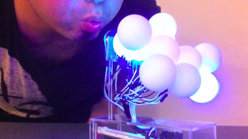
Creating colourful clouds of light

Arduino user SicLeung is part of Do Interactive, an interactive design team based in Hong Kong. He sent us a video about his experimental installation at Hong Kong Poly University – School of Design and exploring unusual ways of activating light:

Old Kit Review – Talking Electronics Fluorescent Simulator

Introduction

Slowly we’re working through the stock of old kits, and in this article we have the “Fluorescent Lamp” simulator from Talking Electronics. To save repeating myself you can read more about Talking Electronics here and watch interviews of the founder Colin Mitchell here.

So why would you want to simulate a fluoro’ tube anyway? Model railways! When your model world moves from day to night, it’s neat to have street lights and so on “flicker” on just like the real thing. And thus you can create this effect as well. It can drive incandescent lamps up to 12V, and allowing it to be powered easily from most layouts.

The kit was originally described in the Talking Electronics book “Electronics for Model Railways” (volume 1) which was full of useful and interesting electronics to liven up any layout. The book may now out of print however at the time of writing this you can download or view most of the projects from the index column of the Talking Electronics website… or contact Talking Electronics if they have any copies of the book (or kit) to sell.

Assembly

Time was not kind to the kit, to be frank it was surprising to find one at all:

(Just a note for any over-enthusiastic readers, Talking Electronics is no longer at the address on the bag shown above). However it was complete and ready for assembly. The PCB has a silk-screen with the required component placement information, polarities and so on – a first for the time:

The instructions and “how it works” are not included with the kit as you were meant to have the book, however TE have made them available as a separate download (.pdf) The kit included everything required to get started, and there’s an LED which replicates the effect so you can test the board without having to watch the connected bulb (which may be a distance away). Finally an IC socket is included

The actual assembly process was very straight forward, which simply required starting with the low-profile components and working up to the large ones:

The only problem with the PCB was the holes – looks like only one drill size had been used (apart from the mounting holes) which made getting that rectifier diode in a little tricky. Otherwise it was smooth sailing.

Not having a model railway at the moment left me with the simple example of the onboard LED and a small incandescent globe to try with the circuit. You can see the kit working in this video.

John – Why do you publish these “Old Kit Reviews”?

They’re more of  a selfish article, like many electronics enthusiasts I have enjoyed kits for decades – and finding kits from days gone by is a treat. From various feedback some of you are enjoying them, so they will continue for fun and some nostalgia. If you’re not interested, just ignore the posts starting with “Old”!

Conclusion

For a kit from the mid-1980s, this would have solved the problem neatly for model railway enthusiasts. By using two or more of the kits with different capacitor values, many model lights could blink on with seemingly random patterns. However it’s 2014 so you could use a PIC10F200 or ATtiny45 and reduce the board space and increase the blinking potential.

Nevertheless, it was an interesting example of what’s possible with a digital logic IC. Full-sized images and a lot more information about the kit are available on flickr. And if you enjoyed this article, or want to introduce someone else to the interesting world of Arduino – check out my book (now in a third printing!) “Arduino Workshop”.

Have fun and keep checking into tronixstuff.com. Why not follow things on twitterGoogle+, subscribe  for email updates or RSS using the links on the right-hand column, or join our forum – dedicated to the projects and related items on this website. Sign up – it’s free, helpful to each other –  and we can all learn something.

The post Old Kit Review – Talking Electronics Fluorescent Simulator appeared first on tronixstuff.
Pics captured during programming RGB LED...

Thats an interesting an captivating slideshow of some pics captured during programming a RGB LED to glow in different shades through Arduino...
Let's Make Robots 06 Feb 14:04

Plantoid Robot: Rimor Mundus, Terrapod v2

Primary image

What does it do?

Uses data based on the condition of a plant in a terraruim ecosystem to explore and react to the outer world.


Cost to build

$160,00

Embedded video

Finished project

Number

Time to build

8 hours

Type

legs

URL to more information

Weight

300 grams

read more

Light chasing autonomous rover

Primary image

What does it do?

Chases light source and avoids obstacles

I started 2 years ago with an autonomous rover that chases light and avoids obstacles. We're now 11 versions further and version 12 is almost ready! Eventually the rover must cruise around without hitting any objects and return to a charging station when the battery runs low. I'll show you the evolution of the rover, starting with version 2 (version 1 was crap)


Version 2

Cost to build

$250,00

Embedded video

Finished project

Number

Time to build

230 hours

Type

URL to more information

Weight

1500 grams

read more

Let's Make Robots 23 Jan 23:29

Light Seeking Car (Moth Car)

Primary image

What does it do?

Navigate around according to ambient light

Let me introduce you to my Moth Car! The Moth Car is made from the chassis of an old RC car I found out in the shed. Forgotten and deteriorating away I decided to give it a new life.

I carefully de-soldered the wires from the battery pack and DC motors and kept the receiver for another day. Using the Adafruit motor shield for the Arduino Uno I connected the cables. Making sure that everything was connected properly and operational I uploaded some test code and thankfully it all worked.

Cost to build

Embedded video

Finished project

Complete

Number

Time to build

Type

URL to more information

Weight

read more

Blinking light switch

In addition to being a great replacement for that aging eye patch, these specs act as a light switch. By watching your eyelids, they are able to kill the lights whenever you blink.

The installation is a shared experience piece conceived by [Michal Kohút]. He wanted to illustrate the constant blinking we all do but rarely think about. The system uses an Arduino to capture events from the blink sensors and switch the lights accordingly. This way the wearer doesn’t experience a loss of illumination, but the observer does. Check out the video after the break for a quick demonstration.

One of the commenters from the source article shared a video link to another blink-based light project. That one uses electrodes attached to skin around your eye in order to detect eyelid motion.

[via Reddit]


Filed under: wearable hacks
Hack a Day 11 Aug 16:01

Incredible RGB LED Cube Tutorial


We’ve seen our fair share of LED light cubes before, but what makes this one different is its incredibly detailed, step-by-step tutorial.   The creator of this light show previously made a one color LED light cube and shared the trials, tribulations and instructions.  He has since decided to go multi-color, again while challenging himself and learning some new tricks along the way.


The project requires 512, 10mm RGB LEDs and an Arduino compatible microcomputer. The creator used wooden strips to create vertical panels of LEDs rather than horizontal layers for ease of building. The building and soldering took about one weekend and the software took about 70 hours. The author saves you time by providing most of the code for you.  Learn how to  fbuild your own RGB LED cube!

Popular LED Projects:

Hack n Mod 11 Jul 11:07

Hipster chandelier

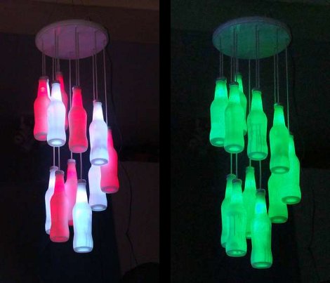
This chandelier is something we’d expect to see on sale in the local gallery store. [Starkec] made it a couple of years back and we just love the look. The materials are pretty common, and you can throw it together in an afternoon.

The diffuser are made from clear glass soda bottles. After removing the labels and giving them a good cleaning, they were each set upside down and sprayed with some glass frosting spray. A four-conductor telephone wire serves both as the support for the bottle and electrical path for the RGB LED inside of each. The original screw cap for the bottles makes it a twist to install them after the soldering is done. There are two common color buses so that alternating colors can be shown at the same time. After seeing the video we think you’ll agree that the wiring scheme makes for some great animated effects.

[Thanks Craig]


Filed under: led hacks
Hack a Day 28 May 19:01
arduino  bottle  chandelier  glass  lamp  led hacks  light  rgb  

Mouse Controlling Arduino LEDs


Use a mouse to control LEDs attached to an Arduino. This project uses the processing language to transmit the mouse coordinates to the Arduino, which then uses this information to turn on some LEDs. Please see the video below to see it in action.


Components Required for this project:

  • Arduino UNO
  • Breadboard
  • 9 LEDs
  • 9 x 330 ohm resistors
  • Wires to connect the circuit
  • USB connection cable: to connect the computer to the Arduino
  • A computer: to run the processing sketch, and to compile / upload the Arduino sketch
  • Processing Program installed on computer
  • Arduino Program installed on the computer

Arduino Sketch


This was made using Fritzing.

Arduino Code

You can download the Arduino IDE from this site.

 1
2
3
4
5
6
7
8
9
10
11
12
13
14
15
16
17
18
19
20
21
22
23
24
25
26
27
28
29
30
31
32
33
34
35
36
37
38
39
40
41
42
/* This program was created by ScottC on 9/5/2012 to receive serial 
signals from a computer to turn on/off 1-9 LEDs */

void setup() {
// initialize the digital pins as an output.
pinMode(2, OUTPUT);
pinMode(3, OUTPUT);
pinMode(4, OUTPUT);
pinMode(5, OUTPUT);
pinMode(6, OUTPUT);
pinMode(7, OUTPUT);
pinMode(8, OUTPUT);
pinMode(9, OUTPUT);
pinMode(10, OUTPUT);
// Turn the Serial Protocol ON
Serial.begin(9600);
}

void loop() {
byte byteRead;

/* check if data has been sent from the computer: */
if (Serial.available()) {

/* read the most recent byte */
byteRead = Serial.read();
//You have to subtract '0' from the read Byte to convert from text to a number.
byteRead=byteRead-'0';

//Turn off all LEDS
for(int i=2; i<11; i++){
digitalWrite(i, LOW);
}

if(byteRead>0){
//Turn on the relevant LEDs
for(int i=1; i<(byteRead+1); i++){
digitalWrite(i+1, HIGH);
}
}
}
}

The code above was formatted using this site.


Processing Code

You can download the Processing IDE from this site.

 1
2
3
4
5
6
7
8
9
10
11
12
13
14
15
16
17
18
19
20
21
22
23
24
25
26
27
28
29
30
31
32
33
34
35
36
37
38
39
40
41
42
43
44
45
46
47
48
49
50
51
52
53
54
//Created by ScottC on 12/05/2012 to send mouse coordinates to Arduino

import processing.serial.*;

// Global variables
int new_sX, old_sX;
int nX, nY;
Serial myPort;

// Setup the Processing Canvas
void setup(){
size( 800, 400 );
strokeWeight( 10 );

//Open the serial port for communication with the Arduino
//Make sure the COM port is correct
myPort = new Serial(this, "COM6", 9600);
myPort.bufferUntil('\n');
}

// Draw the Window on the computer screen
void draw(){

// Fill canvas grey
background( 100 );

// Set the stroke colour to white
stroke(255);

// Draw a circle at the mouse location
ellipse( nX, nY, 10, 10 );

//Draw Line from the top of the page to the bottom of the page
//in line with the mouse.
line(nX,0,nX,height);
}


// Get the new mouse location and send it to the arduino
void mouseMoved(){
nX = mouseX;
nY = mouseY;

//map the mouse x coordinates to the LEDs on the Arduino.
new_sX=(int)map(nX,0,800,0,10);

if(new_sX==old_sX){
//do nothing
} else {
//only send values to the Arduino when the new X coordinates are different.
old_sX = new_sX;
myPort.write(""+new_sX);
}
}

The code above was formatted using this site.