Posts with «fluorescent» label

Old Kit Review – Talking Electronics Fluorescent Simulator

Introduction

Slowly we’re working through the stock of old kits, and in this article we have the “Fluorescent Lamp” simulator from Talking Electronics. To save repeating myself you can read more about Talking Electronics here and watch interviews of the founder Colin Mitchell here.

So why would you want to simulate a fluoro’ tube anyway? Model railways! When your model world moves from day to night, it’s neat to have street lights and so on “flicker” on just like the real thing. And thus you can create this effect as well. It can drive incandescent lamps up to 12V, and allowing it to be powered easily from most layouts.

The kit was originally described in the Talking Electronics book “Electronics for Model Railways” (volume 1) which was full of useful and interesting electronics to liven up any layout. The book may now out of print however at the time of writing this you can download or view most of the projects from the index column of the Talking Electronics website… or contact Talking Electronics if they have any copies of the book (or kit) to sell.

Assembly

Time was not kind to the kit, to be frank it was surprising to find one at all:

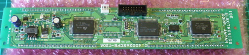
(Just a note for any over-enthusiastic readers, Talking Electronics is no longer at the address on the bag shown above). However it was complete and ready for assembly. The PCB has a silk-screen with the required component placement information, polarities and so on – a first for the time:

The instructions and “how it works” are not included with the kit as you were meant to have the book, however TE have made them available as a separate download (.pdf) The kit included everything required to get started, and there’s an LED which replicates the effect so you can test the board without having to watch the connected bulb (which may be a distance away). Finally an IC socket is included

The actual assembly process was very straight forward, which simply required starting with the low-profile components and working up to the large ones:

The only problem with the PCB was the holes – looks like only one drill size had been used (apart from the mounting holes) which made getting that rectifier diode in a little tricky. Otherwise it was smooth sailing.

Not having a model railway at the moment left me with the simple example of the onboard LED and a small incandescent globe to try with the circuit. You can see the kit working in this video.

John – Why do you publish these “Old Kit Reviews”?

They’re more of  a selfish article, like many electronics enthusiasts I have enjoyed kits for decades – and finding kits from days gone by is a treat. From various feedback some of you are enjoying them, so they will continue for fun and some nostalgia. If you’re not interested, just ignore the posts starting with “Old”!

Conclusion

For a kit from the mid-1980s, this would have solved the problem neatly for model railway enthusiasts. By using two or more of the kits with different capacitor values, many model lights could blink on with seemingly random patterns. However it’s 2014 so you could use a PIC10F200 or ATtiny45 and reduce the board space and increase the blinking potential.

Nevertheless, it was an interesting example of what’s possible with a digital logic IC. Full-sized images and a lot more information about the kit are available on flickr. And if you enjoyed this article, or want to introduce someone else to the interesting world of Arduino – check out my book (now in a third printing!) “Arduino Workshop”.

Have fun and keep checking into tronixstuff.com. Why not follow things on twitterGoogle+, subscribe  for email updates or RSS using the links on the right-hand column, or join our forum – dedicated to the projects and related items on this website. Sign up – it’s free, helpful to each other –  and we can all learn something.

The post Old Kit Review – Talking Electronics Fluorescent Simulator appeared first on tronixstuff.

Using older Noritake Itron VFD modules

Introduction

Now and again you come across interesting parts on ebay, from friends or just rooting around in second-hand stores. One example of this was a huge Noritake Itron 40 x 2 character vacuum-fluorescent display from 1994 (or earlier) which was passed on from a client. Originally it looked quite complex, however after spending some time the data sheets were found and it was discovered to have a simple serial interface – and with a little work we’ve got it working, so read on if you’re interested in classic VFDs or have a similar unit.

Getting Started

The model number for our display is CU40026SCPB-T20A. Here’s a quick walk-around, the front:

… the back:

… the interfaces:

… and configuration jumpers:

The serial interface baud rate is determined by the jumpers (above), for example:

So comparing the table above against the jumpers on our module gives us a data speed of 19200 bps with no parity. Great – we can easily create such a connection with a microcontroller with a serial output and 5V logic levels; for our examples we’ll use an Arduino-compatible board.

Wiring up the VFD is simple – see the white jumpers labelled CN2 as shown previously. Pin 1 is 5V (you need an external supply that can offer up to 700 mA), pin 2 to Arduino digital pin 7, and pin 3 to Arduino and power supply GND. We use Arduino D7 with software serial instead of TX so that the display doesn’t display garbage when a sketch is being uploaded. Then it’s a matter of simply sending text to the display, for example here’s a quick demonstration sketch:

// Working with Noritake Itron VFD modules - model CU40026SCPB-T20A
// John Boxall 2013

#include <SoftwareSerial.h>
SoftwareSerial VFD(6,7); // RX, TX

void setup()
{
  VFD.begin(19200);
}

void loop()
{
  VFD.print("Hello, world. This is a Noritake VFD "); // You can blast out text 
  do {} while (1);
}

… and the results:

If you’re not keen on the colour or intensity of the display, try some Perspex over the top – for example:

Controlling the display

At this point you’ll need the data sheet, there’s a couple you can download: data sheet onedata sheet two. As you saw previously, writing text is very simple – just use .print functions. However you may want to send individual characters, as well as special commands to control aspects of the display. These are outlined in the data sheet – see the “Software Commands” and “Character Fonts” tables.

If you need to send single commands – for example “clear display” which is 0x0E, use a .write command, such as:

VFD.write(0x0E); // clear display

Some commands are in the format of escape codes (remember those?) so you need to send ESC then the following byte, for example to change the brightness to 50%:

VFD.write(0x1B); // ESC
    VFD.write(0x4C); // brightness
    VFD.write(0x40); // 50% brightness

Armed with that knowledge and the data sheets you can now execute all the commands. According to the data sheet it is possible to change fonts however no matter what the hardware jumper or command we tried it wouldn’t budge from the Japanese katakana font. Your screen may vary. If you use the “screen priority write” function heed the data sheet with respect to the extended “busy” time by delaying subsequent writes to the display by a millisecond.

 Putting it all together

Instead of explaining each and every possible command, I’ve put the common ones inside documented functions in the demonstration sketch below, which is followed by a quick video of the sketch in operation.

// Working with Noritake Itron VFD modules - model CU40026SCPB-T20A
// John Boxall 2013

#include <SoftwareSerial.h>
SoftwareSerial VFD(6,7); // rx, tx

void setup()
{
  VFD.begin(19200); // set speed for software serial port 
  resetVFD();  
  VFDclearsceen();
//  VFD.write(0x12); // vertical scroll mode (on)
}

void resetVFD()
// performs a software reset on the VFD controller
{
  VFD.write(0x1B); // ESC
  VFD.write(0x49); // software reset
}

void VFDnewline()
// moves cursor to start of next line
{
  VFD.write(0x0D); // carriage return
  VFD.write(0x0A); // line feed
}

void VFDclearsceen()
// moves cursor to top-left and clears display
{
  VFD.write(0x0E); // clear display 
  VFD.write(0x0C); // form feed - cursor to top-left
}

void VFDbrightness(int amount)
// sets VFD brightness - 25/50/75/100%
// uses ESC sequences
{
  switch(amount)
  {
  case 25:
    VFD.write(0x1B); // ESC
    VFD.write(0x4C); // brightness
    VFD.print(0); // 25% brightness
    break;
  case 50:
    VFD.write(0x1B); // ESC
    VFD.write(0x4C); // brightness
    VFD.write(0x40); // 50% brightness
    break;
  case 75:
    VFD.write(0x1B); // ESC
    VFD.write(0x4C); // brightness
    VFD.write(0x80); // 75% brightness
    break;
  case 100:
    VFD.write(0x1B); // ESC
    VFD.write(0x4C); // brightness
    VFD.write(0xC0); // 100% brightness
  }
}

void VFDchars()
// run through characters for selected font
{
  for (int i = 21 ; i < 256; i++)
  {
    VFD.write(0x16); // underline cursor off
    VFD.write(i);
    delay(100);
  }
}

void moveCursor(byte position)
// moves the cursor - top row is 0~39, bottom row is 40~79
// vertical scroll mode must be turned off if used
{
    VFD.write(0x1B); // ESC
    VFD.write(0x48); // move cursor 
    VFD.write(position); // location
}

void loop()
{
  VFD.write(0x16); // underline cursor off
  VFD.print("Hello, world - line one."); // You can blast out text 
  delay(1000);      
  VFDnewline();
  VFD.print("Hello, world - line two."); 
  delay(1000);    
  VFDclearsceen();
  VFDbrightness(25);
  VFD.print("*** 25% brightness ***");   
  delay(1000);
  VFDclearsceen();  
  VFDbrightness(50);
  VFD.print("*** 50% brightness ***");     
  delay(1000);
  VFDclearsceen();   
  VFDbrightness(75);
  VFD.print("*** 75% brightness ***");       
  delay(1000);
  VFDclearsceen();   
  VFDbrightness(100);
  VFD.print("*** 100% brightness ***");         
  delay(1000);
  VFDclearsceen();

  VFDchars();
  VFDclearsceen();

  for (int i = 0; i < 80; i++)
  {
    VFD.write(0x16); // underline cursor off
    moveCursor(i);
    VFD.print("X");
    delay(100);
    moveCursor(i);    
    VFD.print(" ");    
  }
  VFDclearsceen();
}


Conclusion

We hope you found this interesting and helpful. And if you have an inexpensive source for these old displays, let us know in the comments. Full-sized images are on flickr. And if you made it this far – check out my new book “Arduino Workshop” from No Starch Press.

In the meanwhile have fun and keep checking into tronixstuff.com. Why not follow things on twitterGoogle+, subscribe  for email updates or RSS using the links on the right-hand column? And join our friendly Google Group – dedicated to the projects and related items on this website. Sign up – it’s free, helpful to each other –  and we can all learn something.

The post Using older Noritake Itron VFD modules appeared first on tronixstuff.