Robotic Xylophone Makes Music with MIDI Magic
The MIDI format has long been used to create some banging electronic music, so it’s refreshing to see how [John P. Miller] applied the standard in his decidedly analog self-playing robotic xylophone.
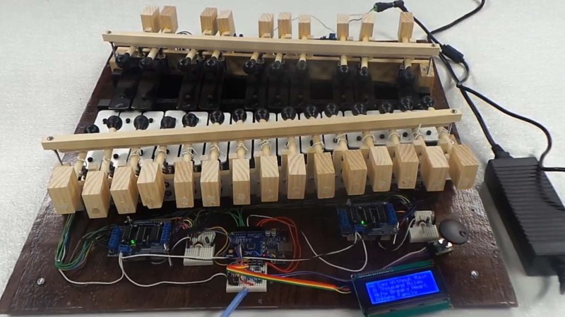
Framed inside a fetching Red Oak enclosure, the 25-key instrument uses individual solenoids for each key, meaning that it has no problem striking multiple bars simultaneously. This extra fidelity really helps in reproducing the familiar melodies via the MIDI format. The tracks themselves can be loaded onto the device via SD card, and selected for playback with character LCD and rotary knob.
The software transposes the full MIDI music spectrum of a particular track into a 25-note version compatible with the xylophone. Considering that a piano typically has 88 keys, some musical concessions are needed to produce a recognizable playback, but overall it’s an enjoyable musical experience.
Perhaps most remarkable about this project is the documentation. If you want to build your own, everything you need to know is available online, and the no-solder approach makes this project very accessible. Most of the write-up happened some years ago, and we’re really interested to see what improvements have been made since.
The robotic xylophone is reminiscent of these automatic tubular bells from some time ago. These musical hacks can be particularly inspiring, and we can’t wait to see more.
[Thanks Assad Ebrahim for the great tip.]