Posts with «schematics» label

Pocket Radio Powered By Tiny Microcontroller

Before the days of MP3 players and smartphones, and even before portable CD players, those of us of a certain age remember that our cassette players were about the only way to take music on-the-go. If we were lucky, they also had a built-in radio for when the single tape exhausted both of its sides. Compared to then, it’s much easier to build a portable radio even though cassettes are largely forgotten, as [wagiminator] shows us with this radio design based on an ATtiny.

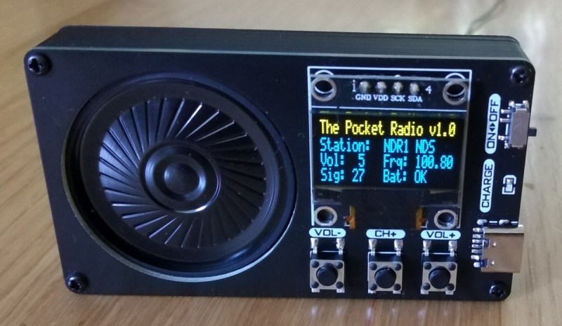
The build is about as compact as possible, with the aforementioned ATtiny 402/412 as its core, it also makes use of an integrated circuit FM tuner,  an integrated audio amplifier with its own single speaker, and a small OLED display. The unit also boasts its own lithium-polymer battery charger and its user interface consists of only three buttons, plenty for browsing radio stations and controlling volume.

The entire build fits easily in the palm of a hand and is quite capable for a mobile radio, plus all of the schematics and code is available on the project page. While it doesn’t include AM capability, just the fact that FM is this accessible nowadays when a few decades ago it was cutting-edge technology is quite remarkable. If you’re looking for an even smaller FM receiver without some of the bells and whistles of this one, take a look at this project too.

Hack a Day 06 Jul 21:00
arduino  attiny  audio  code  fm  oled  radio  radio hacks  schematics  speaker  

Useful Arduino & ATMega microcontrollers pinout diagrams

Pighixxx, from the Arduino forum, has created several pinout diagrams for the Arduino UNO and for several ATMega microcontrollers, such as the ATMega 328 and the ATMega 1284p.

These diagrams provide a clear picture about how to use each pin of the board and can be used as real “cheatsheets” for your own DIY projects. You can download them from here. Enjoy!

Arduino Blog 10 Feb 08:00

A simple Arduino-based tachometer


Chris, from PyroElectro.com, proposes a comprehensive tutorial on how to make a simple, yet effective, Arduino-based tachometer.
The circuit is very simple: an IR led is coupled with an IR phototransistor to detect possible interruptions of the light beam, while the Arduino is responsible to calculate the time interval between two such events. Finally, a LCD is used to display the current RPM to the user.
To validate his project, a typical computer fan has been used in the set-up and the outcomes have demonstrated to be very close to the true RPM value (2600 +/- 100 RPMs).
The bill of materials, as well as the schematic, the source code and a detailed tutorial on how to build the circuit is available here.

[Via: PyroElectro.com]


Arduino Blog 06 Sep 20:10

Going from Schematic to Breadboard

In the new edition of the Arduino Cookbook, Michael Margolis gives a great step-by-step explanation of how to read a schematic and build a breadboard prototype from it. The following excerpt is adapted from Appendix B of the Cookbook.

Using Schematic Diagrams

A schematic diagram, also called a circuit diagram, is the standard way of describing the components and connections in an electronic circuit. It uses iconic symbols to represent components, with lines representing the connections between the components.

A circuit diagram represents the connections of a circuit, but it is not a drawing of the actual physical layout. Although you may initially find that drawings and photos of the physical wiring can be easier to understand than a schematic, in a complicated circuit it can be difficult to clearly see where each wire gets connected.

Circuit diagrams are like maps. They have conventions that help you to orient yourself once you become familiar with their style and symbols. For example, inputs are usually to the left, outputs to the right; 0V or ground connections are usually shown at the bottom of simple circuits, the power at the top.

Here are some of the most common components, and the symbols used for them in circuit diagrams:


Here is a schematic diagram that illustrates the symbols used in a typical diagram:

Components such as the resistor and capacitor used here are not polarized—they can be connected either way around. Transistors, diodes, and integrated circuits are polarized, so it is important that you identify each lead and connect it according to the diagram.

This drawing shows how the wiring could look when connected using a breadboard:

The finished breadboard illustrations were produced using a tool called Fritzing that enables the drawing of electronic circuits.

Wiring a working breadboard from a circuit diagram is easy if you break the task into individual steps. The next illustration shows how each step of breadboard construction is related to the circuit diagram.

The finished circuit is from Recipe 1.6 in the Cookbook, which produces a sound that is controlled by a light dependent resistor.

More: