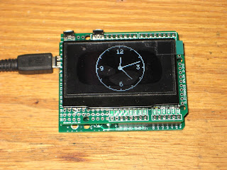
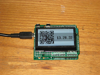
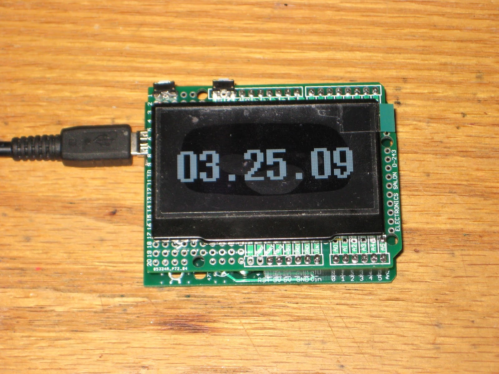
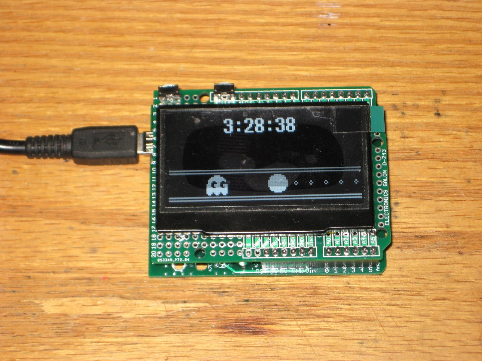
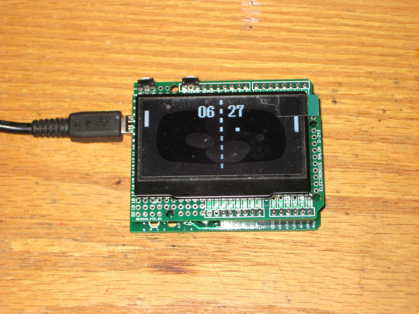
The 2.4" I2C OLED display I had sitting idle is too big for the "Promini OLED Clock shield", yet a perfect candidate for a regular Arduino shield. This is how it looks soldered on a prototype shield with two buttons on top, attached to wsduino running the OLED Clock sketch (each of the 5 faces shown):
The current sketch uses U8glib library and takes about 27k of ATmega328's 31k program memory. It could be enhanced by adding alarm (buzzer, relay etc.), since most of the digital pins are available (only D3 and D9 are used for the 2 buttons). Adding NTP time sync (with an ESP8266 module) could also be done, but one/some of the faces will need to be dropped because of memory constraints. All these are exercises/homework for the inquiring minds :)
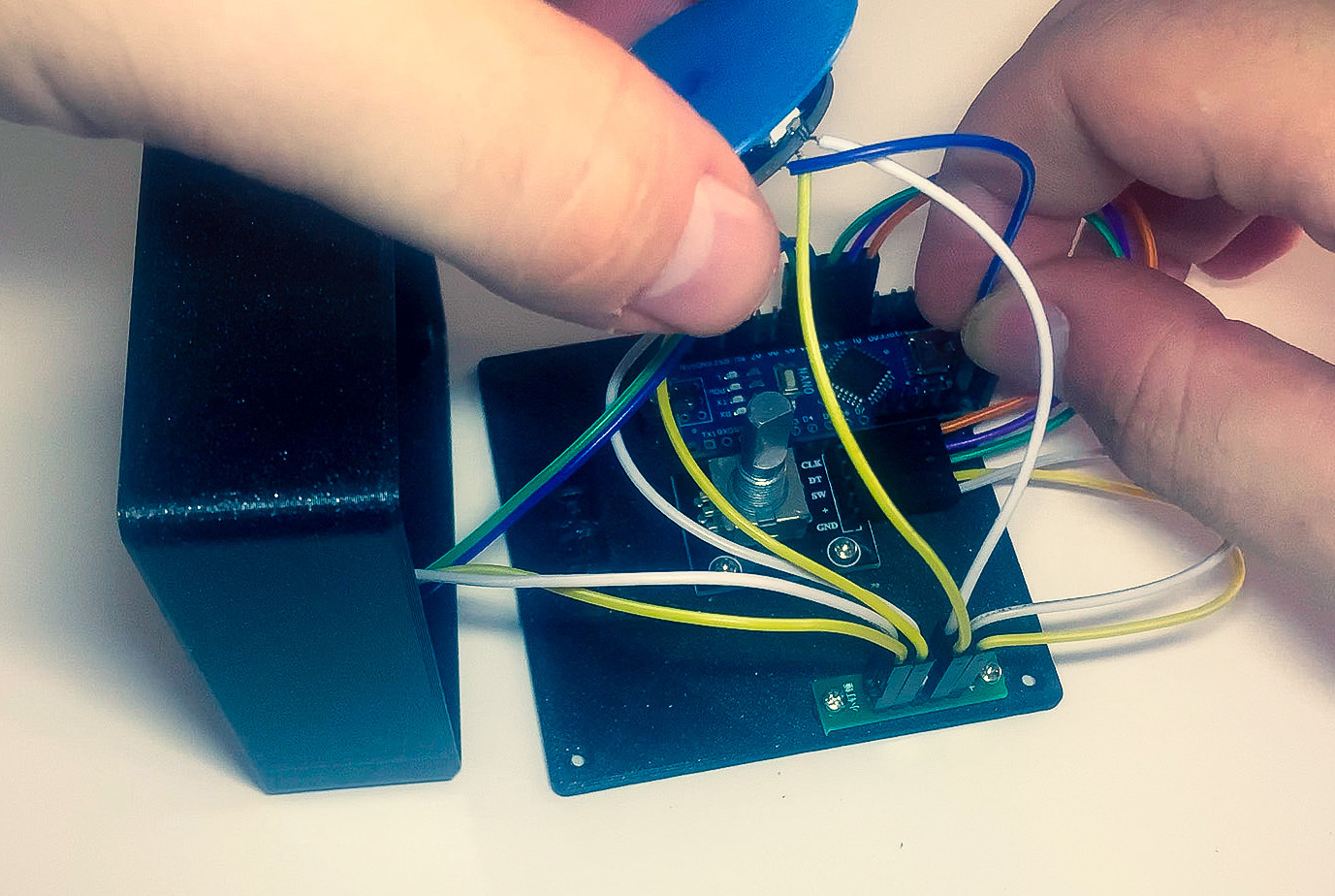
We’ve all been there. You’re manning the battle station, deep in the sim-racing or some other n00b-pwning zone and suddenly some loudmouth blows out your eardrums over Discord. It’s insulting to have to stop what you’re doing to find the right Windows volume slider. So why do that? Build [T3knomanzer]’s simple yet elegant multi-volume knob and stay zen in the zone.
It’s easy, just turn the knob to cycle through your programs until Discord comes up on the little screen, and then push down to change it into a volume knob. If you need to change another volume, just click it again. Since there’s no Alt+Tabbing out to the desktop, no checkered flags should ever slip through your fingers.
Inside the well-designed case you’ll find the usual suspects — Arduino Nano, rotary encoder, an OLED display, and an LED ring, each with their own place carved out.
This completely open-source knob looks great, and we love that it’s been made incredibly easy to replicate by standing up a site with foolproof, well-depicted, step-by-step instructions. Watch them take it for a spin after the break.
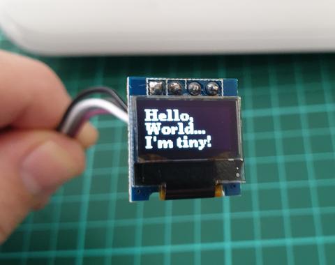
In this article we look at the tiny 0.49″ 64×32 graphic OLED from PMD Way. It is a compact and useful display, that only requires a small amount of time to get working with your Arduino or compatible board.
The purpose of this guide is to get your display successfully operating with your Arduino, so you can move forward and experiment and explore further types of operation with the display.
This includes installing the Arduino library, making a succesful board connection and running a demonstration sketch. So let’s get started!
Connecting the display to your Arduino
The display uses the I2C data bus for communication, and is a 5V and 3.3V-tolerant board.
Arduino Uno to Display
GND ---- GND (GND)

5V/3.3V- Vcc (power supply, can be 3.3V or 5V)

A5 ----- SCL (I2C bus clock)

A4 ----- SDA (I2C bus data)
I2C pinouts vary for other boards. Arduino Leonard uses D2/D3 for SDA and SCL or the separate pins to the left of D13. Arduino Mega uses D20/D21 for SDA and SCL. If you can’t find your I2C pins on other boards, email admin at tronixstuff dot com for assistance.
Installing the Arduino library
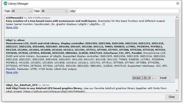
To install the library – simply open the Arduino IDE and select Manage Libraries… from the Tools menu. Enter “u8g2” in the search box, and after a moment it should appear in the results as shown in the image below. Click on the library then click “Install”:
After a moment the library will be installed and you can close that box.
Now it’s time to check everything necessary is working. Open a new sketch in the IDE, then copy and paste the following sketch into the IDE (you may find the “view raw” link at the end useful):
Your display should go through the demonstration of various font sizes and so on as shown in the video below:
You can see how we’ve used a different font in the sketch – at lines 19, 30 and 38. The list of fonts included with the library are provided at https://github.com/olikraus/u8g2/wiki/fntlistall.
Note that the initial location for each line of text (for example in line 20):
u8g2.drawStr(0, 5, "Hello,"); // write something to the internal memory
The x and y coordinates (0,5) are for the bottom-left of the first character.
If you want to display values, not text – such as integers, use:
u8g2.print();
… an example of which is show around line 49 in the example sketch.
Where to from here?
Now it’s time for you to explore the library reference guide which explains all the various functions available to create text and graphics on the display, as well as the fonts and so on. These can all be found on the right-hand side of the driver wiki page.
And that’s all for now. This post brought to you by pmdway.com – everything for makers and electronics enthusiasts, with free delivery worldwide.
To keep up to date with new posts at tronixstuff.com, please subscribe to the mailing list in the box on the right, or follow us on twitter @tronixstuff.
The purpose of this guide is to have an SSD1306-based OLED display successfully operating with your Arduino, so you can move forward and experiment and explore further types of operation with the display.
This includes installing the Arduino library, making a succesful board connection and running a demonstration sketch. So let’s get started!
Connecting the display to your Arduino
The display uses the I2C data bus for communication, and is a 5V and 3.3V-tolerant board.
Arduino Uno to Display
GND ---- GND (GND)

5V/3.3V- Vcc (power supply, can be 3.3V or 5V)

A5 ----- SCL (I2C bus clock)

A4 ----- SDA (I2C bus data)
I2C pinouts vary for other boards. Arduino Leonard uses D2/D3 for SDA and SCL or the separate pins to the left of D13. Arduino Mega uses D20/D21 for SDA and SCL. If you can’t find your I2C pins on other boards, ask your display supplier.
Installing the Arduino library
To install the library – simply open the Arduino IDE and select Manage Libraries… from the Tools menu. Enter “u8g2” in the search box, and after a moment it should appear in the results as shown in the image below. Click on the library then click “Install”:
After a moment the library will be installed and you can close that box.
Now it’s time to check everything necessary is working. Open a new sketch in the IDE, then copy and paste the following sketch into the IDE:
// Display > https://pmdway.com/products/0-96-128-64-graphic-oled-displays-i2c-or-spi-various-colors#include<Arduino.h>#include<U8x8lib.h>#ifdefU8X8_HAVE_HW_SPI#include<SPI.h>#endif#ifdefU8X8_HAVE_HW_I2C#include<Wire.h>#endifU8X8_SSD1306_128X64_NONAME_HW_I2Cu8x8(/* reset=*/U8X8_PIN_NONE);/* This example will probably not work with the SSD1606, because of the internal buffer swapping*/voidsetup(void){/* U8g2 Project: KS0108 Test Board *///pinMode(16, OUTPUT);//digitalWrite(16, 0); /* U8g2 Project: Pax Instruments Shield: Enable Backlight *///pinMode(6, OUTPUT);//digitalWrite(6, 0); u8x8.begin();//u8x8.setFlipMode(1);}voidpre(void){u8x8.setFont(u8x8_font_amstrad_cpc_extended_f);u8x8.clear();u8x8.inverse();u8x8.print(" U8x8 Library ");u8x8.setFont(u8x8_font_chroma48medium8_r);u8x8.noInverse();u8x8.setCursor(0,1);}voiddraw_bar(uint8_tc,uint8_tis_inverse){uint8_tr;u8x8.setInverseFont(is_inverse);for(r=0;r<u8x8.getRows();r++){u8x8.setCursor(c,r);u8x8.print(" ");}}voiddraw_ascii_row(uint8_tr,intstart){inta;uint8_tc;for(c=0;c<u8x8.getCols();c++){u8x8.setCursor(c,r);a=start+c;if(a<=255)u8x8.write(a);}}voidloop(void){inti;uint8_tc,r,d;pre();u8x8.print("github.com/");u8x8.setCursor(0,2);u8x8.print("olikraus/u8g2");delay(2000);u8x8.setCursor(0,3);u8x8.print("Tile size:");u8x8.print((int)u8x8.getCols());u8x8.print("x");u8x8.print((int)u8x8.getRows());delay(2000);pre();for(i=19;i>0;i--){u8x8.setCursor(3,2);u8x8.print(i);u8x8.print(" ");delay(150);}draw_bar(0,1);for(c=1;c<u8x8.getCols();c++){draw_bar(c,1);draw_bar(c-1,0);delay(50);}draw_bar(u8x8.getCols()-1,0);pre();u8x8.setFont(u8x8_font_amstrad_cpc_extended_f);for(d=0;d<8;d++){for(r=1;r<u8x8.getRows();r++){draw_ascii_row(r,(r-1+d)*u8x8.getCols()+32);}delay(400);}draw_bar(u8x8.getCols()-1,1);for(c=u8x8.getCols()-1;c>0;c--){draw_bar(c-1,1);draw_bar(c,0);delay(50);}draw_bar(0,0);pre();u8x8.drawString(0,2,"Small");u8x8.draw2x2String(0,5,"Scale Up");delay(3000);pre();u8x8.drawString(0,2,"Small");u8x8.setFont(u8x8_font_px437wyse700b_2x2_r);u8x8.drawString(0,5,"2x2 Font");delay(3000);pre();u8x8.drawString(0,1,"3x6 Font");u8x8.setFont(u8x8_font_inb33_3x6_n);for(i=0;i<100;i++){u8x8.setCursor(0,2);u8x8.print(i);// Arduino Print functiondelay(10);}for(i=0;i<100;i++){u8x8.drawString(0,2,u8x8_u16toa(i,5));// U8g2 Build-In functionsdelay(10);}pre();u8x8.drawString(0,2,"Weather");u8x8.setFont(u8x8_font_open_iconic_weather_4x4);for(c=0;c<6;c++){u8x8.drawGlyph(0,4,'@'+c);delay(300);}pre();u8x8.print("print \\n\n");delay(500);u8x8.println("println");delay(500);u8x8.println("done");delay(1500);pre();u8x8.fillDisplay();for(r=0;r<u8x8.getRows();r++){u8x8.clearLine(r);delay(100);}delay(1000);}
Your display should go through the demonstration of various things as shown in the video below:
If the display did not work – you may need to manually set the I2C bus address. To do this, wire up your OLED then run this sketch (open the serial monitor for results). It’s an I2C scanner tool that will return the I2C bus display.
Then use the following line in void setup():
u8x8.setI2CAddress(address)
Replace u8x8 with your display reference, and address with the I2C bus address (for example. 0x17).
Moving on…
By now you have an idea of what is possible with these great-value displays.
Now your display is connected and working, it’s time to delve deeper into the library and the various modes of operations. There are three, and they are described in the library documentation – click here to review them.
Whenever you use one of the three modes mentioned above, you need to use one of the following constructor lines:
U8G2_SSD1306_128X64_NONAME_F_HW_I2C u8g2(U8G2_R0, /* reset=*/ U8X8_PIN_NONE); // full buffer mode
U8X8_SSD1306_128X64_NONAME_HW_I2C u8x8(/* reset=*/ U8X8_PIN_NONE); // 8x8 character mode
Match the mode you wish to use with one of the constructors above. For example, in the demonstration sketch you ran earlier, we used the 8×8 character mode constructor in line 14.
Where to from here?
Now it’s time for you to explore the library reference guide which explains all the various functions available to create text and graphics on the display, as well as the fonts and so on. These can all be found on the right-hand side of the driver wiki page.
This post brought to you by pmdway.com – everything for makers and electronics enthusiasts, with free delivery worldwide.
To keep up to date with new posts at tronixstuff.com, please subscribe to the mailing list in the box on the right, or follow us on twitter @tronixstuff.
When building projects with a simple goal in mind, it’s not unheard of for us to add more and more switches, buttons, and complexity as the project goes through its initial prototyping stages. Feature creep like this tends to result in a tangled mess rather than a usable project. With enough focus, though, it’s possible to recognize when it’s happening and keep to the original plans. On the other hand, this single-button project with more than one use seems to be the opposite of feature creep. (YouTube, embedded below.)
[Danko]’s project has one goal: be as useful as possible while only using a single button and a tiny screen. Right now the small handheld device can be used as a stopwatch, a counter, and can even play a rudimentary version of flappy bird. It uses an Arduino Pro Mini, a 64×48 OLED screen running on I2C, and has a miniscule 100 mAh 3.7V battery to power everything. The video is worth watching if you’ve never worked with this small of a screen before, too.
Getting three functions out of a device with only one button is a pretty impressive feat, and if you can think of any other ways of getting more usefulness out of something like this be sure to leave it in the comments below. [Danko] is no stranger to simple projects with tiny screens, either. We recently featured his homebrew Arduino calculator that uses an even smaller screen.
A pocket watch, tucked into a waistcoat pocket and trailing a long chain, is a retro-hip accessory. A pocket watch gutted of its mechanical innards and updated as a smart appliance might be a horological abomination, but would still be a cool hack. A pocket watch converted to a digital Enigma machine is in a class all by itself.
[Simon] admits that he has a thing for pocket timepieces, having a sizable collection of old and not-so-old watches, some that even serve for everyday carry. Trouble is, they eventually break, and qualified watchmakers are getting hard to come by. So refitting defunct watches has become a hobby for him, and this example is a doozy. It uses an Enigma emulator running on an Arduino, similar to one that he stuffed into a somewhat oversized wristwatch a few years ago. Fitting it into a pocket watch case required a bit of finagling, including a 0.5-mm thick main PCB that flexes a bit to fit the contours of the case. A small OLED screen peeks through the front bezel, which is done up in an attractive black crinkle finish with brass buttons for a nice retro look. There’s even an acid-etched brass badge on the front cover with his special logo, complete with a profile of the original Enigma rotors.
In case you happen to have an ocean nearby, you’re probably familiar with its rising and falling tides. And if mudflat hiking is a thing in your area, you’re also aware of the importance of good timing and knowing when the water will be on its way back. Tide clocks will help you to be prepared, and they are a fun alternative to your usual clock projects. If you’re looking for a starting point, [rabbitcreek] put together an Arduino-based tide clock kit for educational purposes.
If you feel like you’re experiencing some déjà vu here, this indeed isn’t [rabbitcreek]’s first tide clock project. But unlike his prior stationary clock, he has now created a small and portable, coin-cell version to take with you out on the sea. And what shape would better fit than a 3D printed moon — unfortunately the current design doesn’t offer much waterproofing.
We live in a world in which nearly any kind of gadget or tool you can imagine is just a few clicks away. In many respects, this has helped fuel the maker culture over the last decade or so; now that people aren’t limited to the hardware that’s available locally, they’re able to create bigger and better things than ever before. But it can also have a detrimental effect. One has to question, for instance, why they should go through the trouble of building something themselves when they could buy it, often for less than the cost of the individual components.
The critic could argue that many of the projects that grace the pages of Hackaday could be supplanted with commercially available counterparts. We don’t deny it. But the difference between buying a turn-key product and building an alternative yourself is that you can make it exactly how you want it. That is precisely why [Sam Izdat] created this truly one of a kind microphone preamplifier. Could he have bought one online for cheaper? Probably. Could he have saved himself an immense amount of time and effort? Undoubtedly. Do we care? Not in the slightest.
The amplifier is based on the Texas Instruments INA217 chip, with an Arduino Nano and 128×64 OLED display providing the visualization. [Sam] was able to find a bare PCB for a typical INA217 implementation on eBay for a few bucks (see what we mean?), which helped get him started and allowed him to spend more time on the software side of things. His visualization code offers a number of interesting display modes, uses Fast Hartley Transforms, and very nearly maxes out the Arduino.
But perhaps no element of this build is as unique as the case. The rationale behind the design is that [Sam] wanted to compartmentalize each section of the device (power supply, amplifier, visualization) to avoid any interference. The cylindrical shapes were an issue of practicality: the compartments were constructed by using a hole saw to make wooden discs, which were then glued together and hollowed out. The case was stained and coated with polyurethane, but due to some slightly overzealous use of glue and fillers, the coloring isn’t uniform. This gives the final piece a somewhat weathered look, in sharp contrast to the decidedly high-tech looking display.
A good deal of the projects we cover here at Hackaday are not, in the strictest sense, practical endeavors. If we required that everything which graced our digital pages had a clear end result, the site would be in a rather sad state of affairs. Sometimes it’s enough just to do something for the challenge of it. But more often than not, you’ll learn something in the process which you can use down the line.
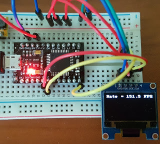
That’s precisely what pushed [Laurence Bank] to see how well he could optimize the frame rate on the popular SSD1306 OLED display. After several iterations of his code, he was able to achieve a blistering 151.5 FPS, with apparently still some room for improvement if he’s feeling up to the challenge. But considering his first attempt was only running at 5.5 FPS, we’d say he’s already more than earned his hacker cred on this one.
A few different tricks were used to achieve such incredible performance gains. To start with, while the official I2C specification says you’re supposed to wait for an acknowledgment back from the device when communicating with it, [Laurence] realized the SSD1306 didn’t actually care. He could continuously blast commands at the display without bothering to wait for an acknowledgment. He admits there are problems with this method, but you can’t argue with the results.
To really wring all the performance out of the system he could, [Laurence] donned his Assembly Cap and examined how the Arduino IDE compiler was interpreting his code. He identified a few areas where changing his C code would force the compiler to generate faster output. He notes that this wouldn’t normally be required when working with more advanced compilers, but that the Arduino toolchain needs its hand held occasionally.
Who would have thought you could make a game out of an optical bench? [Chris Mitchell] did, and while we were skeptical at first, his laser Light Bender game has some potential. Just watch your eyes.
The premise is simple: direct the beam of a colored laser to the correct target before time runs out. [Chris] used laser-cut acrylic for his playfield, which has nine square cutouts arranged in a grid. Red, green, and blue laser pointers line the bottom of the grid, with photosensors and RGB LEDs lining the grid on the other three sides. Play starts with a random LED lighting up in one of the three colors, acting as a target. The corresponding color laser comes on, and the player has to insert mirrors or pass-through blocks in the grid to create a path to the target. The faster you hit the CdS cell, the higher your score. It’s simple, but it looks really engaging. We can imagine all sorts of upgrades, like lighting up two different targets at once, or adding a beamsplitter block to hit two targets with the same color. Filters and polarizers could add to the optical fun too.
We like builds that are just for fun, especially when they’re well-crafted and have a slight air of danger. The balloon-busting killbots project we featured recently comes to mind.