Posts with «arduino tachometer» label

Build a tachometer for your metal lathe with Arduino

If you manage to get a small lathe in your home shop, it will likely come with a dial to adjust the speed, but it may not have a tachometer to tell you if it’s actually spinning at your desired setting. Rather than accept this imprecision on his model, hacker Tony Scarpelli designed his own non-contact tachometer using an Arduino Nano.

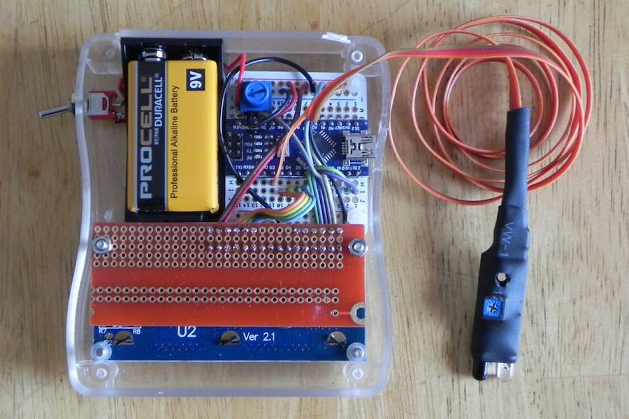
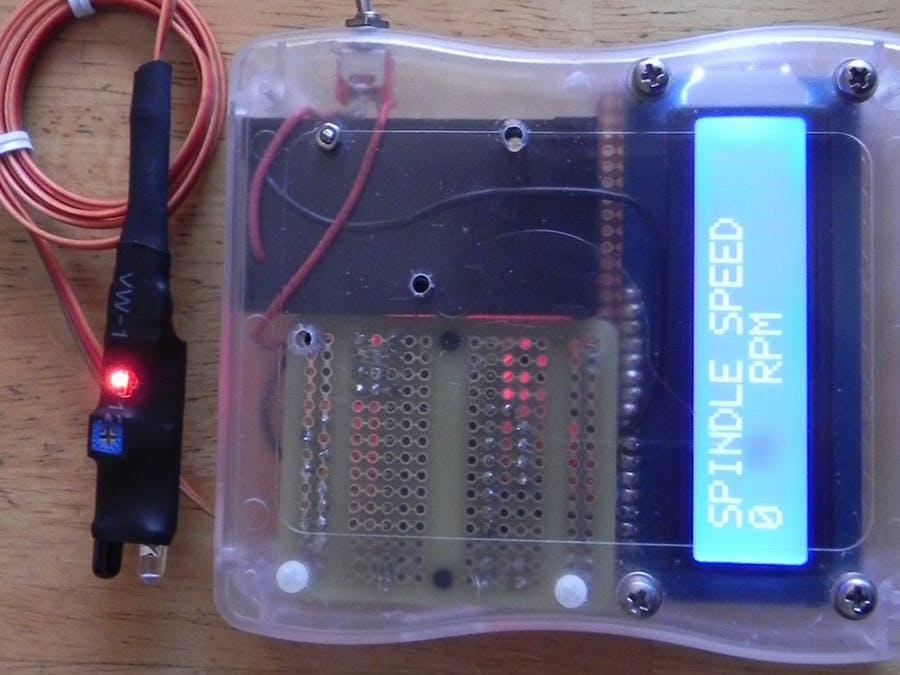
The build is ingeniously simple, and mounts an infrared proximity sensor near gearing in the back of the lathe’s headstock. White paper is placed on this rotating surface, allowing the sensor to tell between this marker and the otherwise dark surface as it spins. Sensor pulses are recorded by the Arduino, which outputs RPM values on a small 16×2 LCD display.

An Arduino tachometer for your older vehicle

Unlike most cars today, deepsyx’s old Opel Astra did not have a tachometer. So what’s a Maker to do? Build your own, of course.

To accomplish this, deepsyx used an Arduino Uno along with a few LEDs. The first LED turns on at 4000 RPM, while the others light up with every 500 RPM increment. At 5800 RPM, however, all the LEDs flash as a warning. There’s even a serial output of the RPM value, so logging real-time data can be a possible enhancement down the road.

I started by cutting a 5cm x 1.5cm piece of an old credit cart, drilled 4 holes in it, painted it black and glued 4 LED diodes to it. Then I soldered 220ohm resistors to each positive LED pin and used a common ground. I connected them to an Arduino via 5 x 30cm jumpers and hid the Arduino in a hole under the wheel. I connected the Arduino data pin via voltage divider to the signal pin of the coil and used an old phone charger to power the Arduino. In order to work, I shared the phone charger and Arduino’s grounds.

Intrigued? You can read more about this project on deepsyx’sGitHub page and over on Hackaday.