Posts with «serial» label

Showcase your project: ListComPorts per Windows

Marco Lai ci propone un software da lui sviluppato per semplificare la gestione delle porte COM su di un sistema Windows, nel caso vengano utilizzate differenti schede Arduino in una volta sola:

Spesso mi capita di usare diversi tipi di Arduino collegati allo stesso pc e diventa abbastanza frustrante capire quale sia la relativa porta COM, dato che nell’IDE viene elencato il nome della porta senza la descrizione del tipo di dispositivo associato.
Quindi devo accedere a gestione dispositivi e controllare nella voce Port (COM e LPT) quale sia questa associazione, in modo da caricare gli sketch sui giusto relativi dispositivi.
Il problema poi aumenta quando collego e scollego le schede dalla porta usb, magari invertendo l’ordine sulle porte, ottenendo così nuovi assegnamenti di COM che mi costringono a tenere aperta la finestra gestione dispositivi.
Ho scritto una piccola utility che elenca le porte COM con la descrizione del dispositivo collegato, in questo modo lavoro meglio e quando ricollego le schede posso cliccare sul pulsante aggiorna per ottenere la nuova lista aggiornata.

Maggiori informazioni, così come il link per scaricare ListComPorts, possono essere trovate qui.

Arduino Blog 15 Feb 16:00
com  port  serial  software  

Pocket Serial Host acts as an Apple II disk drive

[Osgeld] is showing off what he calls a sanity check. It’s the first non-breadboard version of his Pocket Serial Host. He’s been working on the project as a way to simplify getting programs onto the Apple II he has on his “retro bench”. When plugged in, the computer sees it as a disk drive.

The storage is provided by an SD card which is hidden on the underside of that protoboard. This makes it dead simple to hack away at your programs using a modern computer, then transfer them over to the retro hardware. The components used (starting at the far side of the board) are a DB9 serial connector next to a level converter to make it talk to the ATmega328 chip being pointed at with a tool. The chip below that is a level converter to get the microcontroller talking to the RTC chip seen to the right. The battery keeps that clock running when there’s no power from the 5V and 3.3V regulators mounted in the upper right.

The video after the break shows off this prototype, the breadboard circuit, and a demonstration with the Apple II.

[Thanks Brendan]


Filed under: classic hacks, computer hacks

Processing communicating with Arduino via Bluetooth problems

I am at my wits end! Ive spent the last three or so hours trying to get this to work with no avail.

read more

Let's Make Robots 05 Feb 09:29
arduino  avr  bluetooth  com  hc-05  processing  serial  

Bluetooth Tutorial 1


Introduction:
The bluetooth shield used in this project is a great way to detach the Arduino from your computer. What is even better, is that the shield allows you to control your arduino from your mobile phone or other bluetooth enabled device through simple Serial commands. In this tutorial we will connect a Grove Chainable RGB LED to the bluetooth shield directly, and send simple commands using the Bluetooth SPP app on a Samsung Galaxy S2 to change the colour of the LED (Red , Green and Blue)


Parts Required:
Freetronics Eleven or any compatible Arduino.
Bluetooth shield
Grove Chainable RGB LED
Grove Wire connectors


The Video:


The Arduino Sketch:


Arduino Code:
You can download the Arduino IDE from this site.


 1
2
3
4
5
6
7
8
9
10
11
12
13
14
15
16
17
18
19
20
21
22
23
24
25
26
27
28
29
30
31
32
33
34
35
36
37
38
39
40
41
42
43
44
45
46
47
48
49
50
51
52
53
54
55
56
57
58
59
60
61
62
63
64
65
66
67
68
69
70
71
72
73
74
75
76
77
78
79
80
81
82
83
84
85
86
87
88
89
90
91
92
93
94
95
96
97
98
99
100
101
102
103
104
105
106
107
108
109
110
111
112
113
114
115
116
117
118
119
120
121
122
123
124
125
126
127
128
129
130
131
132
133
134
135
136
137
138
139
140
141
142
143
144
145
146
147
148
149
150
151
152
153
154
155
156
157
158
159
/* This project combines the code from a few different sources.
This project was put together by ScottC on the 15/01/2013
http://arduinobasics.blogspot.com/

Bluetooth slave code by Steve Chang - downloaded from :
http://www.seeedstudio.com/wiki/index.php?title=Bluetooth_Shield

Grove Chainable RGB code can be found here :
http://www.seeedstudio.com/wiki/Grove_-_Chainable_RGB_LED#Introduction

*/

#include <SoftwareSerial.h> //Software Serial Port

#define uint8 unsigned char
#define uint16 unsigned int
#define uint32 unsigned long int

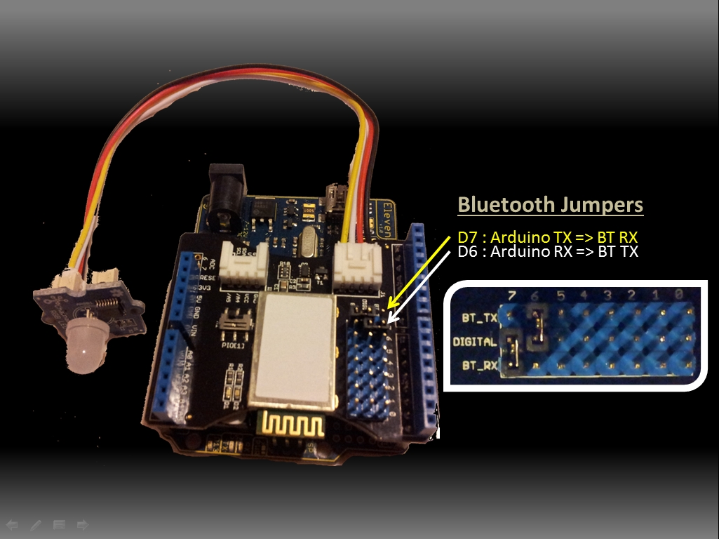
#define RxD 6 // This is the pin that the Bluetooth (BT_TX) will transmit to the Arduino (RxD)
#define TxD 7 // This is the pin that the Bluetooth (BT_RX) will receive from the Arduino (TxD)

#define DEBUG_ENABLED 1


int Clkpin = 9; //RGB LED Clock Pin (Digital 9)
int Datapin = 8; //RGB LED Data Pin (Digital 8)

SoftwareSerial blueToothSerial(RxD,TxD);

/*----------------------SETUP----------------------------*/
void setup() {
Serial.begin(9600); // Allow Serial communication via USB cable to computer (if required)
pinMode(RxD, INPUT); // Setup the Arduino to receive INPUT from the bluetooth shield on Digital Pin 6
pinMode(TxD, OUTPUT); // Setup the Arduino to send data (OUTPUT) to the bluetooth shield on Digital Pin 7
pinMode(13,OUTPUT); // Use onboard LED if required.
setupBlueToothConnection(); //Used to initialise the Bluetooth shield

pinMode(Datapin, OUTPUT); // Setup the RGB LED Data Pin
pinMode(Clkpin, OUTPUT); // Setup the RGB LED Clock pin

}

/*----------------------LOOP----------------------------*/
void loop() {
digitalWrite(13,LOW); //Turn off the onboard Arduino LED
char recvChar;
while(1){
if(blueToothSerial.available()){//check if there's any data sent from the remote bluetooth shield
recvChar = blueToothSerial.read();
Serial.print(recvChar); // Print the character received to the Serial Monitor (if required)

//If the character received = 'r' , then change the RGB led to display a RED colour
if(recvChar=='r'){
Send32Zero(); // begin
DataDealWithAndSend(255, 0, 0); // first node data
Send32Zero(); // send to update data
}

//If the character received = 'g' , then change the RGB led to display a GREEN colour
if(recvChar=='g'){
Send32Zero(); // begin
DataDealWithAndSend(0, 255, 0); // first node data
Send32Zero(); // send to update data
}

//If the character received = 'b' , then change the RGB led to display a BLUE colour
if(recvChar=='b'){
Send32Zero(); // begin
DataDealWithAndSend(0, 0, 255); // first node data
Send32Zero(); // send to update data
}
}

//You can use the following code to deal with any information coming from the Computer (serial monitor)
if(Serial.available()){
recvChar = Serial.read();

//This will send value obtained (recvChar) to the phone. The value will be displayed on the phone.
blueToothSerial.print(recvChar);
}
}
}


//The following code is necessary to setup the bluetooth shield ------copy and paste----------------
void setupBlueToothConnection()
{
blueToothSerial.begin(38400); //Set BluetoothBee BaudRate to default baud rate 38400
blueToothSerial.print("\r\n+STWMOD=0\r\n"); //set the bluetooth work in slave mode
blueToothSerial.print("\r\n+STNA=SeeedBTSlave\r\n"); //set the bluetooth name as "SeeedBTSlave"
blueToothSerial.print("\r\n+STOAUT=1\r\n"); // Permit Paired device to connect me
blueToothSerial.print("\r\n+STAUTO=0\r\n"); // Auto-connection should be forbidden here
delay(2000); // This delay is required.
blueToothSerial.print("\r\n+INQ=1\r\n"); //make the slave bluetooth inquirable
Serial.println("The slave bluetooth is inquirable!");
delay(2000); // This delay is required.
blueToothSerial.flush();
}


//The following code snippets are used update the colour of the RGB LED-----copy and paste------------
void ClkProduce(void){
digitalWrite(Clkpin, LOW);
delayMicroseconds(20);
digitalWrite(Clkpin, HIGH);
delayMicroseconds(20);
}

void Send32Zero(void){
unsigned char i;
for (i=0; i<32; i++){
digitalWrite(Datapin, LOW);
ClkProduce();
}
}

uint8 TakeAntiCode(uint8 dat){
uint8 tmp = 0;
if ((dat & 0x80) == 0){
tmp |= 0x02;
}

if ((dat & 0x40) == 0){
tmp |= 0x01;
}

return tmp;
}

// gray data
void DatSend(uint32 dx){
uint8 i;
for (i=0; i<32; i++){
if ((dx & 0x80000000) != 0){
digitalWrite(Datapin, HIGH);
} else {
digitalWrite(Datapin, LOW);
}

dx <<= 1;
ClkProduce();
}
}

// data processing
void DataDealWithAndSend(uint8 r, uint8 g, uint8 b){
uint32 dx = 0;

dx |= (uint32)0x03 << 30; // highest two bits 1,flag bits
dx |= (uint32)TakeAntiCode(b) << 28;
dx |= (uint32)TakeAntiCode(g) << 26;
dx |= (uint32)TakeAntiCode(r) << 24;

dx |= (uint32)b << 16;
dx |= (uint32)g << 8;
dx |= r;

DatSend(dx);
}

The code above was formatted using hilite.me

Notes:
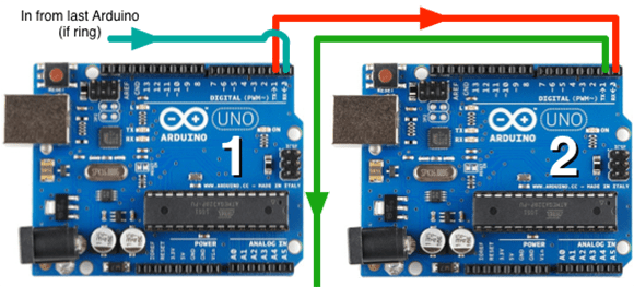
You don't need to download a library to get this project running. But if you plan to use bluetooth shields to get 2 Arduinos to communicate to each other, then I would advise that you download the library files (which are just examples) from the Seeedstudio site : here.

Visit this site to setup your phone or laptop for bluetooth communication to the shield - here

The app used on my Samsung Galaxy S2 phone was "Bluetooth SPP"

You will initially need to enter a pin of '0000' to establish a connection to the Bluetooth shield - which will appear as "SeeedBTSlave" or whatever text you place on line 90 of the Arduino code above.


Warning !

Not all phones are compatible with the bluetooth shield.
If you have used this shield before - please let me know what phone you used - so that we can build a list and inform others whether their phone is likely to work with this project or not. Obviously - those phones that do not have bluetooth within - will not work :).
And I have not tried any other apps either

I got it to work very easily with my Samsung Galaxy S2 using the free Bluetooth SPP app from the google play store.

This was fun, but I want to make my own app !
Have a look at my latest 4-part tutorial which takes you step-by-step through the process of building your own app using the Processing/Android IDE.
You can build your own GUI interface on your Android Phone and get it to communicate via Bluetooth to your Arduino/Bluetooth Shield. Click on the links below for more information:


If you like this page, please do me a favour and show your appreciation :

 
Visit my ArduinoBasics Google + page.
Follow me on Twitter by looking for ScottC @ArduinoBasics.
Have a look at my videos on my YouTube channel.


However, if you do not have a google profile...
Feel free to share this page with your friends in any way you see fit.

Serial monitoring

Hi.

Does anybody know of a decent freebie transparent serial monitor? I've been having some trouble with processing and arduino, (see this), and I'd like to be able to compare what processing and the arduino terminal are sending so I can find the problem.

Thans in advance.

Let's Make Robots 16 Dec 11:58
arduino  avr  processing  serial  

Talk to my computer through Serial?

Long time no see LMR!!!!

This semester was my most brutal yet, but the rewards have been priceless!


Anyways, back to the robots,

So my current project is to create a virtual indentity that I can have a VERY simple conversation with. His name is Sergei, cause everyone needs an awesome Russian buddy. But I find myself being a bit stuck on one thing: Serial Communications


What Im really trying to better understand is how to make the Arduino respond to my serial input. 

read more

How-To: Daisy Chain Arduinos via Serial

If you have a project that uses a bunch of Arduinos, how can you get them to communicate together? Scott Lawrence from The Geodesic Sphere shows us how to daisy chain multiple Arduinos together via their serial ports. He used this technique for his long-term Animatronic Avian project inspired by [...]

Read the full article on MAKE

MAKE » Arduino 03 Dec 18:30

Inventing networking protocols for dozens of Arduinos

When you don’t want to use I2C or SPI, and MIDI and DMX are old hat, [Scott] comes along and invents a very strange networking protocol that is just daisy chaining a few Arduinos together with serial connections.

Strange as it may seem, this networking protocol actually makes a whole lot of sense. [Scott] is working on an animatronic birdhouse in the vein of Disney’s Imagineers and needed to network a whole bunch of Arduinos without using up precious IO pins.

The networking stack [Scott] came up with capitalizes on the hardware UART in each Arduino by simply daisy-chaining several boards together. By adding an FTDI breakout at the beginning of the chain, [Scott] can control dozens of Arduinos straight from a terminal

[Scott] isn’t using off-the-shelf Arduinos for this project – a few months ago he found 100 Arduino-compatible stepper motor controllers while dumpster diving at his job, giving him more than enough nodes to come up with some pretty crazy networking protocols. It’s a great use of the hardware he has on hand, and a very clever solution to controlling dozens of microcontrollers at once.

Check out [Scott]‘s demo after the break.


Filed under: arduino hacks
Hack a Day 03 Dec 13:00

Processing-Arduino serial port problem

I've picked up an arduino to start working with, and have currently slung together a bit of code to toggle the on-board LED over serial. I've also modified one of the Processing demos to use as a GUI to turn it on and off. However, my arduino is on COM6, and if I try to change the port on Processing to anything other than 0, it comes up with an error. I know the arduino code works, as I've tried it with the arduino serial terminal, however the processing app doesn't want to play ball.

read more

Let's Make Robots 17 Nov 21:02
arduino  avr  processing  serial  

HC-SR04 Ultrasonic Sensor


Introduction:

The HC-SR04 Ultrasonic Sensor is a very affordable proximity/distance sensor that has been used mainly for object avoidance in various robotics projects . It essentially gives your Arduino eyes / spacial awareness and can prevent your robot from crashing or falling off a table. It has also been used in turret applications, water level sensing, and even as a parking sensor. This simple project will use the HC-SR04 sensor with an Arduino and a Processing sketch to provide a neat little interactive display on your computer screen.


Parts Required:
Freetronics Eleven or any compatible Arduino.
HC-SR04 Ultrasonic Sensor
Mini Breadboard 4.5cm x 3.5cm
Protoshieldand female header pins (not essential - but makes it more tidy)
Wiresto connect it all together


The Video:


The Arduino Sketch:


     The above sketch was created using Fritzing.


Arduino Code:
You can download the Arduino IDE from this site.

 1
2
3
4
5
6
7
8
9
10
11
12
13
14
15
16
17
18
19
20
21
22
23
24
25
26
27
28
29
30
31
32
33
34
35
36
37
38
39
40
41
42
43
44
45
46
47
48
49
50
51
52
53
54
55
56
57
58
59
60
/*
HC-SR04 Ping distance sensor:
VCC to arduino 5v
GND to arduino GND
Echo to Arduino pin 7
Trig to Arduino pin 8

This sketch originates from Virtualmix: http://goo.gl/kJ8Gl
Has been modified by Winkle ink here: http://winkleink.blogspot.com.au/2012/05/arduino-hc-sr04-ultrasonic-distance.html
And modified further by ScottC here: http://arduinobasics.blogspot.com.au/2012/11/arduinobasics-hc-sr04-ultrasonic-sensor.html
on 10 Nov 2012.
*/


#define echoPin 7 // Echo Pin
#define trigPin 8 // Trigger Pin
#define LEDPin 13 // Onboard LED

int maximumRange = 200; // Maximum range needed
int minimumRange = 0; // Minimum range needed
long duration, distance; // Duration used to calculate distance

void setup() {
Serial.begin (9600);
pinMode(trigPin, OUTPUT);
pinMode(echoPin, INPUT);
pinMode(LEDPin, OUTPUT); // Use LED indicator (if required)
}

void loop() {
/* The following trigPin/echoPin cycle is used to determine the
distance of the nearest object by bouncing soundwaves off of it. */
digitalWrite(trigPin, LOW);
delayMicroseconds(2);

digitalWrite(trigPin, HIGH);
delayMicroseconds(10);

digitalWrite(trigPin, LOW);
duration = pulseIn(echoPin, HIGH);

//Calculate the distance (in cm) based on the speed of sound.
distance = duration/58.2;

if (distance >= maximumRange || distance <= minimumRange){
/* Send a negative number to computer and Turn LED ON
to indicate "out of range" */
Serial.println("-1");
digitalWrite(LEDPin, HIGH);
}
else {
/* Send the distance to the computer using Serial protocol, and
turn LED OFF to indicate successful reading. */
Serial.println(distance);
digitalWrite(LEDPin, LOW);
}

//Delay 50ms before next reading.
delay(50);
}

The code above was formatted using hilite.me


Processing Code:
You can download the Processing IDE from this site.

 1
2
3
4
5
6
7
8
9
10
11
12
13
14
15
16
17
18
19
20
21
22
23
24
25
26
27
28
29
30
31
32
33
34
35
36
37
38
39
40
41
42
43
44
45
46
47
48
49
50
51
52
53
54
55
56
57
58
59
60
61
62
63
64
65
66
67
68
69
70
71
72
73
74
75
76
77
78
79
80
81
82
83
84
85
86
87
88
89
90
91
92
93
94
95
96
97
98
99
100
101
102
103
104
105
106
107
108
109
110
111
112
113
114
115
116
117
118
119
120
121
122
123
124
125
126
127
128
/* The following Processing Sketch was created by ScottC on
the 10 Nov 2012 : http://arduinobasics.blogspot.com/

Inspired by this Processing sketch by Daniel Shiffman:
http://processing.org/learning/basics/sinewave.html

*/
import processing.serial.*;


int numOfShapes = 60; // Number of squares to display on screen
int shapeSpeed = 2; // Speed at which the shapes move to new position
// 2 = Fastest, Larger numbers are slower

//Global Variables
Square[] mySquares = new Square[numOfShapes];
int shapeSize, distance;
String comPortString;
Serial myPort;

/* -----------------------Setup ---------------------------*/
void setup(){
size(displayWidth,displayHeight); //Use entire screen size.
smooth(); // draws all shapes with smooth edges.

/* Calculate the size of the squares and initialise the Squares array */
shapeSize = (width/numOfShapes);
for(int i = 0; i<numOfShapes; i++){
mySquares[i]=new Square(int(shapeSize*i),height-40);
}

/*Open the serial port for communication with the Arduino
Make sure the COM port is correct - I am using COM port 8 */
myPort = new Serial(this, "COM8", 9600);
myPort.bufferUntil('\n'); // Trigger a SerialEvent on new line
}

/* ------------------------Draw -----------------------------*/
void draw(){
background(0); //Make the background BLACK
delay(50); //Delay used to refresh screen
drawSquares(); //Draw the pattern of squares
}


/* ---------------------serialEvent ---------------------------*/
void serialEvent(Serial cPort){
comPortString = cPort.readStringUntil('\n');
if(comPortString != null) {
comPortString=trim(comPortString);

/* Use the distance received by the Arduino to modify the y position
of the first square (others will follow). Should match the
code settings on the Arduino. In this case 200 is the maximum
distance expected. The distance is then mapped to a value
between 1 and the height of your screen */
distance = int(map(Integer.parseInt(comPortString),1,200,1,height));
if(distance<0){
/*If computer receives a negative number (-1), then the
sensor is reporting an "out of range" error. Convert all
of these to a distance of 0. */
distance = 0;
}
}
}


/* ---------------------drawSquares ---------------------------*/
void drawSquares(){
int oldY, newY, targetY, redVal, blueVal;

/* Set the Y position of the 1st square based on
sensor value received */
mySquares[0].setY((height-shapeSize)-distance);

/* Update the position and colour of each of the squares */
for(int i = numOfShapes-1; i>0; i--){
/* Use the previous square's position as a target */
targetY=mySquares[i-1].getY();
oldY=mySquares[i].getY();

if(abs(oldY-targetY)<2){
newY=targetY; //This helps to line them up
}else{
//calculate the new position of the square
newY=oldY-((oldY-targetY)/shapeSpeed);
}
//Set the new position of the square
mySquares[i].setY(newY);

/*Calculate the colour of the square based on its
position on the screen */
blueVal = int(map(newY,0,height,0,255));
redVal = 255-blueVal;
fill(redVal,0,blueVal);

/* Draw the square on the screen */
rect(mySquares[i].getX(), mySquares[i].getY(),shapeSize,shapeSize);
}
}

/* ---------------------sketchFullScreen---------------------------*/
// This puts processing into Full Screen Mode
boolean sketchFullScreen() {
return true;
}

/* ---------------------CLASS: Square ---------------------------*/
class Square{
int xPosition, yPosition;

Square(int xPos, int yPos){
xPosition = xPos;
yPosition = yPos;
}

int getX(){
return xPosition;
}

int getY(){
return yPosition;
}

void setY(int yPos){
yPosition = yPos;
}
}

The code above was formatted using hilite.me


If you like this page, please do me a favour and show your appreciation :

  Visit my ArduinoBasics Google + page.
Follow me on Twitter by looking for ScottC @ArduinoBasics.
Have a look at my videos on my YouTube channel.


However, if you do not have a google profile...
Feel free to share this page with your friends in any way you see fit.