Posts with «arduinobasics» label

Simple Arduino Serial Communication (Part 2)

In Stages 1 to 5 , we experimented with the Serial Monitor on the Arduino IDE to transmit data to the Arduino and receive data from the Arduino. We performed simple Serial communication of data in both directions.

We then moved from transmitting a String of characters to the more difficult task of transmitting a double or a float.

Finally, we used the Serial monitor to receive sensor data from our Arduino, and played with a couple of Arduino functions.

We will now look at replacing the Serial Monitor with a much more exciting program such as "Processing" which is a free Open Source program that interfaces very easily with the Arduino. It can be downloaded here.

We will use a few processing scripts to bring our Arduino Sensor projects to life !


Stage 6: A simple Processing Sketch: BLINK


Arduino IDE vs Processing IDE


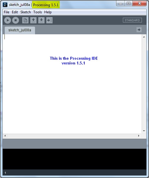
While the processing IDE looks very similar to the Arduino IDE, it is important that you realise that the Processing sketch will run on your computer, and NOT on the Arduino. In fact, you do not even need an Arduino to run a Processing sketch. And that is exactly what we are going to do: Run a Processing sketch without an Arduino.

Parts Required


  • A computer
  • Processing IDE

  • Once you have downloaded and installed the Processing IDE onto your computer, open the program and copy the following sketch into it, and then press the play button. This is different from the Arduino IDE, in that we do not have to upload it to anything, as it will be running from the computer.

    Processing Sketch


    1
    2
    3
    4
    5
    6
    7
    8
    9
    10
    11
    12
    13
    14
    15
    16
    17
    18
    19
    20
    21
    22
    23
    24
    25
    26
    27
    28
    29
    30
    31
    32
    33
    34
    35
    36
    37
    38
    39
    40
    41
    42

    /* Stage 6: Simple Processing Blink Sketch
    Created by ScottC on the 8/7/2012
    http://arduinobasics.blogspot.com/ */


    /* Setup the color variables and switching mechanism */
    color Red=color(255,0,0);
    color White=color(255,255,255);
    Boolean mySwitch=true;


    /* The setup function only runs once */

    void setup(){
    /* Set the size of the window using size(width,height) */
    size(400,400);
    }

    /* The draw function will refresh screen only after it has
    processed all functions within it. Which is why I needed
    a switch to swap between the red and the white background
    The draw() function will run in an endless loop. */

    void draw(){
    blink(mySwitch); //Call to blink function
    delay(2000); //The blinking speed (2 secs)
    }


    /* The blink function switches the background from red to white
    or from white to red. */

    void blink(Boolean swtch){
    /* If swtch is true, make the background red
    otherwise make it white */
    if(swtch){
    background(Red); // red
    }else {
    background(White); // white
    }
    /* Toggle mySwitch between true and false */
    mySwitch=!mySwitch;
    }


    Things to Try


    1. Change the White background to a black background

    2. Insert on line 9: color Black=color(0,0,0);
      Change line 38: background(Black);


    3. Increase the blink rate to 1 second

    4. Change line 25: delay(1000);
      WARNING : Do not increase the speed too much, it may cause an epileptic fit.


    Now that wasn't too hard I hope.
    And if you want a very good site to learn Processing have a look at these


  • The official Processing reference library
  • Official Processing Tutorials
  • Getting started with Processing
  • Daniel Shiffman's Processing Examples and Tutorials


  • Stage 7: Arduino and Processing Unite.


    So how do we get our Arduino to interface with our computer? Well, if the Serial Monitor on the Arduino IDE is not good enough, then you could use any program that is capable of Serial communication. Fortunately, Processing is one of those programs, but you could use C++, Java, Python, Microsoft Excel (using VBA), VB.Net, Gobetwino or some other programming language.

    Two programs will be created: One will be uploaded to the Arduino using the Arduino IDE, and the other will run on the computer. In this example we will use Processing as the program that will run on the computer.

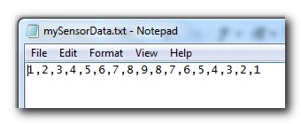
    Enter the following sketch into the Arduino IDE and upload it to the Arduino. It serves to generate a random number between 0 and 400 every 200msec and will send it to the computer via the USB cable , using Serial communication.

    Arduino Sketch


     1
    2
    3
    4
    5
    6
    7
    8
    9
    10
    11
    12
    13
    /* Stage 7: Simple Arduino Serial Random Number Generator
    Written by ScottC on 09/07/2012
    http://arduinobasics.blogspot.com/
    */


    void setup(){
    Serial.begin(9600); //Begin Serial Communication
    }

    void loop(){
    Serial.println(random(1,1000)); //Send Random # to computer
    delay(200); //Delay 200ms between values.
    }


    Instructions

    Once the program has been uploaded to the Arduino, we will want to make sure that it is performing to expectations before moving onto the Processing script.

    Open the Arduino Serial Monitor and make sure that you see a bunch of random numbers scrolling down the page. If not, then go back over your code and try again. Once you see the random numbers, then it is safe to move on to the next step.


    Processing

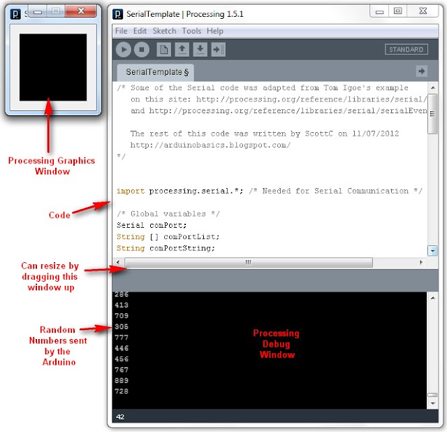
    The following Processing script will display the Random numbers being sent from the Arduino in the Processing IDE debug window. This particular script is very much like a simplified Arduino Serial Monitor, and it will show you that the Processing Script is successfully communicating with the Arduino.


    Processing Sketch

     1
    2
    3
    4
    5
    6
    7
    8
    9
    10
    11
    12
    13
    14
    15
    16
    17
    18
    19
    20
    21
    22
    23
    24
    25
    26
    27
    28
    29
    30
    31
    32
    33
    34
    35
    36
    37
    38
    39
    40
    41
    42
    43
    44
    45
    46
    47
    48
    49
    50
    51
    52
    53
    54
    /* Some of the Serial code was adapted from Tom Igoe's example
    on this site: http://processing.org/reference/libraries/serial/Serial.html
    and http://processing.org/reference/libraries/serial/serialEvent_.html

    The rest of this Processing code was written by ScottC on 11/07/2012
    http://arduinobasics.blogspot.com/
    */


    import processing.serial.*; /* Needed for Serial Communication */

    /* Global variables */
    Serial comPort;
    String [] comPortList;
    String comPortString;

    /*--------------------------------------------------*/

    void setup(){
    size(100,100); /* Set the size of the window */
    background(0); /* Set the background to black */


    /* Get the available com ports. If there is at least one
    com port available, then start communicating on it.
    If there are more than one com ports available, we will
    only open the first one (i.e. comPortList[0])
    The bufferUntil('\n'); statement will generate a serial Event
    when it reads a carriage return */

    comPortList = Serial.list();
    if(comPortList.length>0){
    comPort = new Serial(this, comPortList[0], 9600);
    comPort.bufferUntil('\n');
    }
    }

    /*--------------------------------------------------*/

    void draw(){
    /* The serialEvent function will update the display */
    }

    /*--------------------------------------------------*/

    void serialEvent(Serial cPort){
    comPortString = cPort.readStringUntil('\n');
    if(comPortString != null) {
    comPortString=trim(comPortString);

    /* Print to the Debug screen in Processing IDE */
    println(comPortString);
    }
    }


    When you run the Processing script, a little black window will appear. This is the Processing Graphics window, which is normally where all the action takes place. However in the sketch above, this window does nothing. Instead we make use of the black Debug window which is part of the Processing IDE (below the code window). If everything went to plan, you should see random numbers scrolling down in a similar fashion to the Arduino Serial monitor. Here is an example of what it should look like.


    Things to Try


    1. If you are having problems with COM port selection. Then have a look at the COM port being used on the Arduino IDE to upload sketches to the Arduino. Processing generally uses the same COM port. So make sure to close the Arduino Serial Monitor before running the Processing Sketches.


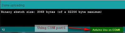
    The image above shows that I am currently using COM PORT 6 on my computer to upload Arduino Sketches. In the Processing sketch on line 32-35, I had this code:

    32
    33
    34
    35
      if(comPortList.length>0){
    comPort = new Serial(this, comPortList[0], 9600);
    comPort.bufferUntil('\n');
    }


    We can change line 33 to get Processing to use COM port 6 exclusively. We do this by replacing comPortList[0] with "COM6", as seen below:

    32
    33
    34
    35
      if(comPortList.length>0){
    comPort = new Serial(this, "COM6", 9600);
    comPort.bufferUntil('\n');
    }


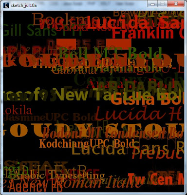
    Stage 8 : Arduino and Processing - Random Font Project


    Arduino and Processing are speaking to each other by this stage, and we will keep our original Arduino Sketch to produce random numbers for us. Sure, we don't actually need the Arduino to do this for us, because Processing is more than capable of doing this itself, but we are building up towards an interactive sketch, so lets just go through the motions.

    Just in case your mouse scroll wheel doesn't move upwards, here is the Arduino Sketch again:

    Arduino Sketch


     1
    2
    3
    4
    5
    6
    7
    8
    9
    10
    11
    12
    13
    /* Stage 8: Simple Arduino Serial Random Number Generator
    Written by ScottC on 09/07/2012
    http://arduinobasics.blogspot.com/
    */


    void setup(){
    Serial.begin(9600); //Begin Serial Communication
    }

    void loop(){
    Serial.println(random(1,1000)); //Send Random # to computer
    delay(100); //Delay 100ms between values.
    }


    Upload the Arduino sketch to the Arduino, and then put the following code into the Processing IDE:

    Processing Sketch


    The output of this sketch should look something like this:


    For stages 9 and above: Click Here


    Simple Arduino Serial Communication

    This Tutorial is progressive and will be updated from time to time. The goal is to start from a very basic form of Arduino Serial communication, and progressively add or improve components so that we can ultimately transmit data from one computer to another using an XBee.
    Please note: I am not an expert, but am happy to share what I have learned. The Arduino forums are a great place to ask questions, feel free to link to this blog (if required).

    Let us begin.


    Stage 1: ECHO ECHO                                                                                    


    Parts Required:

    • Computer
    • USB cable
    • Arduino UNO (or equivalent)
    • Arduino IDE

    The following code will make the Arduino ECHO anything you send to it. Therefore, if you type a 3, the Arduino will send back a 3. If you type a letter F, the Arduino will send back a letter F. 
    Enter the following code into your Arduino IDE and upload it to your Arduino.


    Arduino Sketch


     1
    2
    3
    4
    5
    6
    7
    8
    9
    10
    11
    12
    13
    14
    15
    16
    17
    18
    19
    20
    /* Simple Serial ECHO script : Written by ScottC 03/07/2012 */

    /* Use a variable called byteRead to temporarily store
    the data coming from the computer */
    byte byteRead;

    void setup() {
    // Turn the Serial Protocol ON
    Serial.begin(9600);
    }

    void loop() {
    /* check if data has been sent from the computer: */
    if (Serial.available()) {
    /* read the most recent byte */
    byteRead = Serial.read();
    /*ECHO the value that was read, back to the serial port. */
    Serial.write(byteRead);
    }
    }
    The above code was formatted using this site


    Instructions

    1. Once the Arduino sketch has been uploaded to the Arduino. Open the Serial monitor, which looks like a magnifying glass at the top right section of the Arduino IDE. Please note, that you need to keep the USB connected to the Arduino during this process, as the USB cable is your communication link between your computer and the Arduino.


    2. Type anything into the top box of the Serial Monitor and press <Enter> on your keyboard. This will send a series of bytes to the Arduino. The Arduino will respond by sending back your typed message in the larger textbox.


    3. Please note that we are using Serial.write(byteRead); on line 18 to get the Arduino to ECHO the message back to you on your computer. 


    Things to Try 

    1. Delete lines 16 to 18, and replace them with the following line :

                   Serial.write(Serial.read());

    This essentially eliminates the byteRead variable in the sketch above. But we will be using it later on, so once you have tested it out, put the code back together as originally displayed.


    --------------------------------------------------------------------
    2. Replace line 18 with a Serial.println instead of Serial.write

                   Serial.println(byteRead);

    Once uploaded, type 1 <enter> 2 <enter> 3 <enter>  into the Serial Monitor.
    You should see:

    49
    50
    51

    Serial.print and Serial.println will send back the actual ASCII code, whereas Serial.write will send back the actual text. See ASCII codes for more information.


    --------------------------------------------------------------------
    3. Try typing in numbers like 1.5  or  2.003  or  -15.6 into the Serial Monitor using Serial.write and Serial.print or Serial.println commands as described before.

    You will notice that the decimal point transmits as a number using Serial.print  or Serial.println, and will transmit as a decimal point when using Serial.write


    STAGE 2: Delimiters                                                                                


    How do you handle 2 or more numbers when sending or receiving?
    Let us say that you have number pairs that you want the Arduino to interpret. How do you separate the numbers? The answer is Delimiters.
    You may be familiar with CSV (comma separated value) files, where each field is separated by a comma (,). The comma is a useful way of separating or grouping information.

    Lets say you have the following stream of numbers:
    12345678910

    How will your Arduino know if this is a single number, or a series of numbers?
    Eg:

    12,34,56,78,91,0
    123,456,78,910
    1,2,3,4,5,6,7,8,9,10
    12345678910

    The comma delimiters help to identify how the numbers should be interpreted.

     In the echo example in Stage 1 above, you would have noticed that when we used Serial.print(byteRead); that the values displayed one after another in a similar fashion to 12345678910.

    You would have also noticed that Serial.println(byteRead); provided a line break between each value sent. And depending on the numbers sent, it could have looked like this:
    12
    34
    56
    78
    91
    0

    The Serial.println() function essentially uses a line feed to separate the values being sent. This line break can be used as a delimiter, but we will look at that later on. For now we will concentrate on using a comma (,).

    We will now get the Arduino to "listen" for the comma to help it identify a new number.
    According to the ASCII code site, a comma is equal to byte code 44. So when the Arduino reads a byte code that is equal to 44, we will get it to print a line feed.


    Enter the following sketch into your Arduino IDE and upload it to your Arduino.

    Arduino Sketch


     1
    2
    3
    4
    5
    6
    7
    8
    9
    10
    11
    12
    13
    14
    15
    16
    17
    18
    19
    20
    21
    22
    23
    24
    25
    26
    27
    /* Simple Serial ECHO script : Written by ScottC 04/07/2012 */
    /* Stage 2 : Delimiters */

    /* Use a variable called byteRead to temporarily store
    the data coming from the computer */
    byte byteRead;

    void setup() {
    // Turn the Serial Protocol ON
    Serial.begin(9600);
    }

    void loop() {
    /* check if data has been sent from the computer: */
    if (Serial.available()) {
    /* read the most recent byte */
    byteRead = Serial.read();

    /*Listen for a comma which equals byte code # 44 */
    if(byteRead==44){
    Serial.println();
    }else{
    /*ECHO the value that was read, back to the serial port. */
    Serial.write(byteRead);
    }
    }
    }
    The above code was formatted using this site


    Instructions

    1. Once the code has been uploaded to the Arduino, open the Serial Monitor once again and type the following sequence of numbers:

    1 <enter>  2 <enter> 3 <enter>

    You should see the Serial monitor display the following number:    123


    --------------------------------------------------------------------
    2. While still in the serial monitor, type the following:

    , <enter> 1 <enter> , <enter> 2 <enter> , <enter> 3 <enter> ,

    Please note the commas between each numerical entry. You should now see a pattern like this:
    1
    2
    3


    --------------------------------------------------------------------
    3. While still in the serial monitor, type the following:

    12,23,34,45, <enter>

    Please note the commas between each numerical entry. You should now see a pattern like this:
    12
    23
    34
    45

    You will notice that the commas have been replaced by line feeds, and each number should display on a new line.


    --------------------------------------------------------------------
    4. While still in the serial monitor, type the following:

    1,,2,,3, <enter>

    You should see the following pattern:
    1

    2

    3


    So hopefully that explains the concept of delimiters and how they can be used to separate a stream of numbers, no matter how long it takes to get to the Arduino. We used an IF-statement to listen for the comma, but we could have used any other delimiter provided we knew the byte code.

    We did not identify how to send delimiters FROM the Arduino, but we will get to that I promise. It is not that hard, and uses a similar principle. I am sure you can work it out, if not, stay tuned.


    STAGE 3: Arduino Maths: Simple addition                                                  


    In this stage, we are going to get the Arduino to do simple maths. We will send it two integers (or whole numbers), and the Arduino will do the hard work and send us the answer in no time at all.
    This might seem like a simple task, but when you send a number like 27 to the Arduino, it does not receive the number 27. It receives 2 and then 7 in byte form. In other words, the Arduino will see the byte codes 50 and then 55 as per the ASCII table on this page.

    One way to convert this byte code back to a 2 and a 7 is to subtract 48 from each byte received, providing the byte is in the range 48 to 57 inclusive (which equates to the numbers 0-9).
    We are not done yet. We then need to join these numbers to make 27.

    Step1: Subtract 48 from the bytes received, only if the bytes are in the range 48 to 57.
                     Example:    50 - 48 = 2
                                        55- 48 = 7

    Step2: Multiply the previous number by 10, before adding the most recent byte received.
                     Example:   (2 x 10) + 7 = 27

    If we have a number like 1928, then we would create this number using the following calculation
                                       1 =                         1
                       (1 x 10) + 9 =    10 + 9   =   19
                    (19 x 10) + 2  = 190 + 2   =  192
                  (192 x 10) + 8  = 1920 + 8 = 1928

    Step3: Use a "+" sign as a delimiter so that the Arduino can move onto the Second number

    Step4:  Capture the second number as per Step2. An "=" sign will tell the Arduino that it has reached the end of the second number, and to proceed to step 5.

    Step5:  Add the 2 numbers together and send back the answer.


    The following code will carry out the 5 steps above.
    Enter the following sketch into your Arduino IDE and upload it to your Arduino.

    Arduino Sketch


     1
    2
    3
    4
    5
    6
    7
    8
    9
    10
    11
    12
    13
    14
    15
    16
    17
    18
    19
    20
    21
    22
    23
    24
    25
    26
    27
    28
    29
    30
    31
    32
    33
    34
    35
    36
    37
    38
    39
    40
    41
    42
    43
    44
    45
    46
    47
    48
    49
    50
    51
    52
    53
    54
    55
    56
    57
    58
    59
    60
    61
    62
    63
    64
    /* Simple Serial ECHO script : Written by ScottC 05/07/2012 */
    /* Stage 3: Arduino Maths: Simple Addition */

    /* Global variables needed for programming workflow
    byteRead: holds the value being read from the COM port
    num1: holds the entire first number
    num2: holds the entire second number
    answer: holds the sum of num1 and num2
    mySwitch: enables the switch between num1 and num2 */

    byte byteRead;
    long num1, num2,answer;
    boolean mySwitch=false;

    void setup() {
    /* Turn the Serial Protocol ON and
    initialise num1 and num2 variables.*/
    Serial.begin(9600);
    num1=0;
    num2=0;
    }

    void loop() {
    /* check if data has been sent from the computer: */
    while (Serial.available()) {
    /* read the most recent byte */
    byteRead = Serial.read();

    //listen for numbers between 0-9
    if(byteRead>47 && byteRead<58){
    //number found

    /* If mySwitch is true, then populate the num1 variable
    otherwise populate the num2 variable*/
    if<!mySwitch)><br /> num1=(num1*10)+(byteRead-48);<br /> }<span>else</span>{<br /> num2=(num2*10)+(byteRead-48);<br /> }<br /> }<br /> <br /> <span>/*Listen for an equal sign (byte code 61) </span><br /><span> to calculate the answer and send it back to the</span><br /><span> serial monitor screen*/</span><br /> <span>if</span>(byteRead==61){<br /> answer=num1+num2;<br /> Serial.print(num1);<br /> Serial.print(<span>"+"</span>);<br /> Serial.print(num2);<br /> Serial.print(<span>"="</span>);<br /> Serial.println(answer);<br /> <br /> <span>/* Reset the variables for the next round */</span><br /> num1=0;<br /> num2=0;<br /> mySwitch=<span>false</span>;<br /> <br /> <span>/* Listen for the addition sign (byte code 43). This is</span><br /><span> used as a delimiter to help define num1 from num2 */</span> <br /> }<span>else</span> <span>if</span> (byteRead==43){<br /> mySwitch=<span>true</span>;<br /> }<br /> }<br />}<br /></pre></td></tr></tbody></table></div><br /><span>The above code was formatted using <a href="http://hilite.me/">this site</a></span><br /><br /><br /><h3> <u>Instructions</u></h3><br /><b>1.</b> Once the code has been uploaded to the Arduino, open the Serial Monitor once again and type the following sequence:<br /><br />         <span>1+2=   <enter></span><br /><br />You should get the following message sent back to Serial Monitor<br /><br />        <span> 1+2=3</span><br /><br /><br /><br /><h3> <b><u>Things to Try</u></b></h3><b>1.</b>   Enter this sequence: <br />              <span>10   <enter></span><br /><span>               +   <enter></span><br /><span>              10  <enter></span><br /><span>               =   <enter></span><br /><br />       Result:     <span>10+10=20</span><br /><br /><span>--------------------------------------------------------------------</span><br /><b>2. </b>  Enter this sequence:<br />            <span> 10  <enter></span><br /><span>             20  <enter></span><br /><span>             +5= <enter></span><br /><br /><br />      Result:  <span> 1020+5=1025</span><br /><br /><br /><br /><br /><span>--------------------------------------------------------------------</span><br /><b>3.</b>   Enter this sequence:<br />            <span> 10+20+30=   <enter></span><br /><br /><br />      Result:    <span>10+2030=2040</span><br /><br />I have specifically written this script to add <b>two</b> whole numbers together. If you start to introduce more complicated calculations, the results become unpredictable.<br /><br /><span>--------------------------------------------------------------------</span><br /><b>4.</b>    Enter this sequence:<br />           <span>1.2+1.0=    <enter></span><br /><br />      Result: <span>12+10=22</span><br /><br />Once again, I have only designed this script to handle whole numbers. Therefore, decimal points are ignored.<br /><br /><span>--------------------------------------------------------------------</span><br /><b>5.</b>  Enter this sequence:<br />         <span> -5 + 10=     <enter></span><br /><br /><br />     Result:    <span>5+10=15</span><br /><br /><br />This script ignores the negative sign, and treats the -5 as a positive 5.<br /><br /><br /><div>I have done this on purpose. I wanted to show you how the Arduino reads numbers from the com port, and how easy it is to exclude vital functionality in your code. I have kept this script simple, however, if you wanted to, you could make the Arduino deal with each of the above situations and more.  Multiplication, division and subtraction is handled in the same way. </div><br />This is the last thing I want you to try before we go to the next stage:<br /><br />6. Enter this sequence:<br />           <span>2147483646+1=  <enter></span>           Result:  <span>2147483646+1=2147483647</span><br />          <span> 2147483647+1=  <enter></span>           Result: <span>2147483647+1=</span><span>-</span><span>2147483648</span><br /><br /><br />Note that the maximum size of a "long" number is 2147483647. If you add one to this number, the result is equal to the minimum size of a "long" which is -2147483648.<br /><br /><br /><br /><br /><h3> <b><span><span>STAGE 4:  Sending doubles to Arduino</span> : <span>The double doubler</span>             </span></b></h3><div>Now we get to some tricky business. Sending and receiving Doubles (to and from) the Arduino.<br /><br />Up until now, I have tried to keep it simple using whole numbers, but there will come a time when you will want to send a fraction of a number through the Serial line.</div><div>To test our program, we will want to send a very small number to the Arduino, multiply the number by 2, and return it back.</div><div><br /></div><div>Our final test is to try a number like :  <b>0.000001</b></div><div>             and then a number like:<b>   123.321</b></div><div><br /></div><div><br /><b><span>IMPORTANT NOTE</span></b>:   When the Arduino sends a float or a double through the COM port using Serial.print() or Serial.println(), it will automatically send the number to 2 decimal places.<br />A number like 1.2345 will appear as 1.23,   and a number like 1.9996 will appear as 2.00<br />To demonstrate this, we will get the Arduino to send these floats/doubles to the Serial Monitor.<br /><br /><br /><div>Enter the following sketch into your Arduino IDE and upload it to your Arduino.</div><div><br /></div><h3> <u>Arduino Sketch</u></h3><br /><div><table><tbody><tr><td><pre><span><span> 1<br /> 2<br /> 3<br /> 4<br /> 5<br /> 6<br /> 7<br /> 8<br /> 9<br />10<br />11<br />12<br />13<br />14<br />15<br />16<br />17<br />18<br />19<br />20<br />21<br />22<br />23<br />24<br />25<br />26<br />27<br />28</span></span></pre></td><td><pre><span>/* Stage 4: Simple Transmission of a Double</span><br /><span> Written by ScottC on 7/7/2012 */</span><br /><br /><span>/* Declare the doubles that will be sent to the Serial Monitor */</span><br /> <span>double</span> myDub1, myDub2;<br /><br /><span>/* This part of the program only runs ONCE */</span><br /><br /> <span>void</span> setup(){<br /><br /> <span>/* Turn ON Serial Communication */</span><br /> Serial.begin(9600);<br /> <br /> <span>/* Assign a value 1.2345 and 1.9996 to the Doubles being sent */</span><br /> myDub1=1.2345;<br /> myDub2=1.9996;<br /> <br /> <span>/*Send the values to the Serial Monitor */</span><br /> Serial.print(<span>"myDub1 (1.2345) : "</span>);<br /> Serial.println(myDub1);<br /> Serial.print(<span>"myDub2 (1.9996) : "</span>);<br /> Serial.println(myDub2);<br /> }<br /><br /><br /> <span>void</span> loop(){<br /> <span>//Loop does nothing</span><br /> }<br /></pre></td></tr></tbody></table></div><span>The above code was formatted using </span><a href="http://hilite.me/">this site</a><br /><br />When you open the Serial monitor (after you have uploaded the sketch above), you will notice the following output:<br /><br /><br />         <span> myDub1 (1.2345) :</span> <span>1.23</span><br />         <span> myDub2 (1.9996) :</span> <span>2.00</span><br /><div><br /></div><br /><br />The <span>blue text</span> represents the string (or array of characters) being sent using lines 19 and 21.<br />The <span>red text</span> represents the actual double being sent using lines 20 and 22.<br /><br />You will notice that myDub2 rounds to 2.00.  This may or may not be what you want.<br />If you wish to increase the number of decimal places, then you will need to change lines 20 and 22 to the following:<br /><br /><span><span>20         Serial.println(myDub1,</span><span>4</span><span>)</span>;</span><br /><span><span>22         Serial.println(myDub2,</span><span>4</span><span>);</span></span><br /><br />The number 4 highlighted in red, indicates the number of decimal places you wish to send.<br />Try it ! And try changing this number to something bigger or smaller.<br /><br />---------------------------------------------------------------------------------------------------<br />Ok - now that we understand this little Serial.print(double,decimals) trick, we will now get the Arduino to echo back a Double.<br /><br />Before we jump in, perhaps we should try and map out our strategy. For this we will choose a simple decimal to make it easier. So in this example, we will choose <b>0.1</b></div><div>Once we get this working, we can then do our final test (as mentioned above).</div><div><br /></div><div>If we send 0.1 to the Arduino, it will read the following byte code</div><div><br /></div><div>48                    0</div><div>46                    .</div><div>49                    1</div><div><br /></div><div>We can use the decimal point as a delimiter.<br />We will use the following 5 steps to echo the double back to the Serial Monitor:</div><div><br /></div><div><b><span>Step1</span>:</b> Arduino collects all numbers before the decimal point using the same technique as in Stage3.<br /><br /></div><div><b><span>Step2</span>: </b>When the Arduino receives byte code 46, it will go into decimal mode.<br /><br /></div><div><b><span>Step3</span>:</b> The Arduino will collect numbers after the decimal point using a similar technique to step1.<br /><br /></div><div><b><span>Step4</span>:</b> Use maths to create the double, and then multiply it by 2<br /><br /></div><div><b><span>Step5</span>:</b> Display the doubled Double value in the Serial monitor.</div><div><br /></div><div><br /></div><div><br /><div>Enter the following sketch into your Arduino IDE and upload it to your Arduino.</div><div><br /></div><h3> <u>Arduino Sketch</u></h3></div><div><br /></div><div><table><tbody><tr><td><pre><span><span> 1<br /> 2<br /> 3<br /> 4<br /> 5<br /> 6<br /> 7<br /> 8<br /> 9<br />10<br />11<br />12<br />13<br />14<br />15<br />16<br />17<br />18<br />19<br />20<br />21<br />22<br />23<br />24<br />25<br />26<br />27<br />28<br />29<br />30<br />31<br />32<br />33<br />34<br />35<br />36<br />37<br />38<br />39<br />40<br />41<br />42<br />43<br />44<br />45<br />46<br />47<br />48<br />49<br />50<br />51<br />52<br />53<br />54<br />55<br />56<br />57<br />58<br />59<br />60<br />61<br />62<br />63<br />64<br />65<br />66<br />67<br />68<br />69<br />70<br />71<br />72<br />73<br />74<br />75<br />76<br />77<br />78<br />79<br />80<br />81<br />82<br />83<br />84<br />85</span></span></pre></td><td><pre><span>/* Simple Serial ECHO script : Written by ScottC 06/07/2012 */</span><br /><span>/* Stage 4: Double doubler */</span><br /><br /><span>/* Global variables needed for programming workflow</span><br /><span> ------------------------------------------------------</span><br /><span> byteRead: holds the value being read from the COM port</span><br /><span> num1: holds the number before the decimal point</span><br /><span> num2: holds the number after the decimal point</span><br /><span> complNum: holds the complete number (before multiplation)</span><br /><span> answer: holds the final value after multiplication</span><br /><span> counter: is used to convert num2 to the number after the decimal</span><br /><span> numOfDec: counts the numbers after the decimal point</span><br /><span> mySwitch: enables the switch between num1 and num2 */</span><br /> <br /> byte byteRead;<br /> <span>double</span> num1, num2;<br /> <span>double</span> complNum,answer,counter;<br /> <span>int</span> numOfDec;<br /> boolean mySwitch=<span>false</span>;<br /><br /><br /> <span>void</span> setup() { <br /><span>/* Turn the Serial Protocol ON and </span><br /><span> initialise num1 and num2 variables.*/</span><br /> Serial.begin(9600);<br /> num1=0;<br /> num2=0;<br /> complNum=0;<br /> counter=1;<br /> numOfDec=0;<br /> }<br /><br /> <span>void</span> loop() {<br /><span>/* check if data has been sent from the computer: */</span><br /> <span>while</span> (Serial.available()) {<br /> <span>/* read the most recent byte */</span><br /> byteRead = Serial.read();<br /> <br /> <span>//listen for numbers between 0-9</span><br /> <span>if</span>(byteRead>47 && byteRead<58){<br /> <span>//number found</span><br /> <br /> <span>/* If mySwitch is true, then populate the num1 variable</span><br /><span> otherwise populate the num2 variable*/</span><br /> <span>if</span><!mySwitch)><br /> num1=(num1*10)+(byteRead-48);<br /> }<span>else</span>{<br /> num2=(num2*10)+(byteRead-48);<br /> <br /> <span>/* These counters are important */</span><br /> counter=counter*10;<br /> numOfDec++;<br /> }<br /> }<br /> <br /> <span>/*Listen for an equal sign (byte code 61) </span><br /><span> to calculate the answer and send it back to the</span><br /><span> serial monitor screen*/</span><br /> <span>if</span>(byteRead==61){<br /> <span>/* Create the double from num1 and num2 */</span><br /> complNum=num1+(num2/(counter));<br /> <br /> <span>/* Multiply the double by 2 */</span> <br /> answer=complNum*2;<br /> <br /> <span>/* Send the result to the Serial Monitor */</span> <br /> Serial.print(complNum,numOfDec);<br /> Serial.print(<span>" x 2 = "</span>);<br /> Serial.println(answer,numOfDec);<br /> <br /> <span>/* Reset the variables for the next round */</span><br /> num1=0;<br /> num2=0;<br /> complNum=0;<br /> counter=1;<br /> mySwitch=<span>false</span>;<br /> numOfDec=0;<br /> <br /> <span>/* Listen for the decimal point (byte code 46). This is</span><br /><span> used as a delimiter to help define num1 from num2 */</span> <br /> }<span>else</span> <span>if</span> (byteRead==46){<br /> mySwitch=<span>true</span>;<br /> }<br /> }<br /> }<br /></pre></td></tr></tbody></table></div><div><span>The above code was formatted using </span><a href="http://hilite.me/">this site</a></div><div><br /></div><div><br /></div><div><br /><h3> <b><u>Things to Try</u></b></h3><div><b><u><br /></u></b></div><div>1. Type the following into the serial monitor:</div><div><br /></div><div>       <span>1.2=  <enter></span>                             Result:   <span>1.2 x 2 = 2.4</span></div><div><br /></div><div>Make sure that you type the equal sign (=) before you press enter, otherwise the Arduino will not know that you are finished, and will not send anything back.</div><div><br /></div><div>--------------------------------------------------------------------</div><div>2. Type the following into the serial monitor:</div><div><br /></div><div>      <span>100.001=  <enter></span>                      Result:   <span>100.001 x 2 = 200.002</span></div><div><br /></div><div>You will notice that the Arduino is formatting the decimal to the SAME number of decimals as that entered.</div><div>This is controlled by the variable: <span>numOfDec</span>.</div><div>---------------------------------------------------------------------</div><div>3. Now for our final test: Type the following into the serial monitor:</div><div><br /></div><div>   <span> 0.000001= <enter></span>                       Result: <span>0.000001 x 2 = 0.000002</span></div><div><br /></div><div>First test:<span> PASSED</span></div><div><br /></div><div>----------------------------------------------------------------------</div><div>4. Type the following into the Serial monitor for our last test:</div><div><br /></div><div>     <span>123.321=  <enter></span>                      Result: <span>123.321 x 2 = 246.642</span></div><div><br /></div><div>Second test: <span>PASSED</span></div><div>-----------------------------------------------------------------------</div><div><br /></div><div><span>BEWARE</span>: While everything looks perfect, let me tell you that it isn't. But hopefully this code will help you get on the right track. If you decide to type in a number like 123123.111222, you will not get the answer you expected. </div><div>I have found that this program will work if the amount of numbers before and after the decimal point are less than about 9.  Eg. 1234.1234   will produce the right result.</div><div>However, 11111.2222 will NOT, because there are 9 numbers represented.</div><div><br /></div><div>I think this has something to do with the memory allocated to a double, but I am not sure. </div><div>I don't know if people work with these types of numbers, but I am sure there is a workaround, and I am sure someone out there can work it out. I don't personally need this kind of precision, but thought to mention it just in case you do.</div><div><br /></div><div><br />----------------------------------------------------------------------- <br />----------------------------------------------------------------------- <br /><br /><h3> <b><span><span>STAGE 5:  Sending sensor data to the Serial Monitor</span>             </span></b></h3><br /><br />We know the Arduino is very good at copy-Cat games, how about getting the Arduino to send us some data from one of our sensors. We will use the Serial Monitor to view the sensor data.<br /><br />Disconnect the USB cable, and hook up one of your favourite analog sensors to your Arduino. For simplicity, I am going to hook up a potentiometer as per the Fritzing sketch below.<br /><br /><h3> <u> Parts Required</u></h3><br /><ul><li>Arduino UNO (or equivalent)</li><li>Computer with USB cable</li><li>Breadboard</li><li>Potentiometer</li><li>3 Wires</li></ul><div><br /></div><br /><h3> <u> Arduino Fritzing Sketch</u></h3><br /></div><div><div><a href="http://1.bp.blogspot.com/-JZlWUi3MDck/T_g6ldkqSVI/AAAAAAAAAPY/_UJj4EU3YYE/s1600/Fritzing_Potentiometer_Sketch.jpg"><img src="http://1.bp.blogspot.com/-JZlWUi3MDck/T_g6ldkqSVI/AAAAAAAAAPY/_UJj4EU3YYE/s400/Fritzing_Potentiometer_Sketch.jpg" /></a></div><br /></div><div><br /></div><div>     </div><div><br /></div><div><br /></div></div><br /><br /><br /><br /><br /><br /><br /><br /><br /><br /><br /><br /><br /><br /><br /><br /><br />Once you have attached your sensor to the board, plug your USB cable into the Arduino, and upload the following sketch.<br /><br /><br /><h3> <u>Arduino Sketch</u></h3><div><u><br /></u></div><div><table><tbody><tr><td><pre><span><span> 1<br /> 2<br /> 3<br /> 4<br /> 5<br /> 6<br /> 7<br /> 8<br /> 9<br />10<br />11<br />12<br />13<br />14<br />15<br />16<br />17<br />18<br />19<br />20<br />21</span></span></pre></td><td><pre> <span>/* Stage 5: Send Sensor Value to Serial Monitor</span><br /><span> Written by ScottC on 7/7/2012 */</span><br /><br /> <span>int</span> sensorVal = 0; <br /><br /> <span>void</span> setup() {<br /> <span>// Setup Serial communication with computer</span><br /> Serial.begin(9600);<br /> }<br /><br /> <span>void</span> loop() {<br /> <span>// Read the value from the sensor:</span><br /> sensorVal = analogRead(A0);<br /> <br /> <span>// Send the value to the Serial Monitor</span><br /> Serial.print(<span>"Sensor Value="</span>);<br /> Serial.println(sensorVal);<br /><br /> <span>// Interval between readings = 1 second</span><br /> delay(1000); <br /> }<br /></pre></td></tr></tbody></table></div><div><span>The above code was formatted using </span><a href="http://hilite.me/">this site</a><br /><u><br /></u><br /><u><br /></u><br /><h3> <u>Instructions</u></h3></div></div></div><div>1. Open the Serial monitor and watch the readings change depending on the input conditions. In my case, by turning the potentiometer from left to right, I get an output similar to the picture below.</div><div><br /></div><div><a href="http://2.bp.blogspot.com/-F8H8h8YkXJo/T_g_dcPTN1I/AAAAAAAAAPk/AXQaR5x_UFk/s1600/Serial+Monitor.jpg"><img src="http://2.bp.blogspot.com/-F8H8h8YkXJo/T_g_dcPTN1I/AAAAAAAAAPk/AXQaR5x_UFk/s400/Serial+Monitor.jpg" /></a></div><div><br /></div><div><br /></div><div><br /></div><div><br /></div><div><br /></div><div><br /></div><div><br /></div><div><br /></div><div><br /></div><div><br /></div><div><br /></div><div><br /></div><div><br /></div><div><br /></div><div><br /></div><div><br /></div><div><br /></div><div><br /></div><div><br /></div><div>As per the Arduino reference site, <a href="http://arduino.cc/en/Reference/analogRead">AnalogRead</a> returns an integer between 0 and 1023. You can see this is true based on the picture above. But what if we do not want a value between 0 and 1023. Let us say we want a value between 0 and 100?</div><div><br /></div><div>You would have to use the <a href="http://arduino.cc/en/Reference/Map">map function</a>. We will do it by changing line 13 to this:</div><div><br /></div><div><pre><span><span>13</span></span><span> </span><span><span><b>sensorVal = map(analogRead(A0),0,1023,0,100);</b></span></span></pre></div><div><br /></div><div>The map function is quite a cool function, and good fun to play around with. So here are some things to try.</div><div><h3> <b><u>Things to Try</u></b></h3></div><div>1. Change line 13 to the following, upload to the Arduino </div><div>    and then open the Serial Monitor to see the effect.</div><div><br /></div><div><b><span>Trial 1</span></b>:</div><div><pre><span><span>13</span></span><span> </span><span><span><b>sensorVal = map(analogRead(A0),0,1023,100,0);</b></span></span></pre></div><div><br /></div><div><div><b><span>Trial 2</span></b>:</div><div><pre><span><span>13</span></span><span> </span><span><span><b>sensorVal = map(analogRead(A0),0,1023,0,1000);</b></span></span></pre></div></div><div><br /></div><div><div><span><b>Trial 3</b></span>:</div><div><pre><span><span>13</span></span><span> </span><span><span><b>sensorVal = map(analogRead(A0),200,800,0,100);</b></span></span></pre></div></div><div><br /></div><div><br /></div><div>In <b><span>Trial 1</span></b>: We see that the values have been inverted. Instead of ranging from 0 up to100, they now go from 100 down to 0.</div><div><br /></div><div>In <b><span>Trial 2</span></b>: The analog readings are now mapped to a range of 0 up to 1000. </div><div><br /></div><div>In <b><span>Trial 3</span></b>: The analog readings that range from 200 to 800 are mapped to a range of 0 to 100. Therefore if the analog readings drop below 200, we will end up with a negative value for sensorVal. </div><div>If the analog readings go above 800, we will end up with a value greater than 100.  For this particular example, my readings actually range from  -33 to 137.</div><div><br /></div><div>Therefore an Analog reading of 0 = -33</div><div>                 Analog reading of 200 = 0</div><div>                 Analog reading of 800 = 100</div><div>               Analog reading of 1023 = 137</div><div><br /></div><div><br /></div><div>----------------------------------------------------------------------------------</div><div>What if we don't want the output to go beyond our intended limits of 0 to 100?</div><div>Then you would have to use the <a href="http://arduino.cc/en/Reference/Constrain">constrain function</a>. This essentially trims the reading range of the sensor, and sets a minimum and maximum value.</div><div><br /></div><div>Replace line 13 with the following code:</div><div><br /></div><div><pre><span><span>13</span></span><span> </span><span><span><b>sensorVal = constrain(map(analogRead(A0),200,800,0,100),0,100);</b></span></span></pre></div><div><br /></div><div><div>Therefore an Analog reading of 0 = 0</div><div>                 Analog reading of 100 = 0</div><div>                 Analog reading of 200 = 0</div><div>                 Analog reading of 800 = 100</div><div>                  Analog reading of 955 = 100</div><div>               Analog reading of 1023 = 100</div></div><div>Analog values between 200 and 800 will produce a result between 0 and 100.</div><div><br /></div><div>-------------------------------------------------------------------------------------<br /><br /><h3><span>If you wish to continue with this tutorial (stage 6 and above), please follow this link:  <a href="http://arduinobasics.blogspot.com/2012/07/arduino-basics-simple-arduino-serial_09.html">Serial Communication Stage 6 and above</a> </span></h3></div><div><br /></div><div><br /></div> <br />  <br />  <div> <p> <!--separator --> <img src="https://images-blogger-opensocial.googleusercontent.com/gadgets/proxy?url=http%3A%2F%2F1.bp.blogspot.com%2F-XQiwNpdqOxk%2FT_rKCzDh4nI%2FAAAAAAAAAQY%2FOfYBljhU6Lk%2Fs1600%2FSeparator.jpg&container=blogger&gadget=a&rewriteMime=image%2F*" /><br /> <br /> </p> </div> <p> <div> <p> If you like this page, please do me a favour and show your appreciation : <br /> <br />  <br /> Visit my <a href="https://plus.google.com/u/0/b/107402020974762902161/107402020974762902161/posts">ArduinoBasics Google + page</a>.<br /> Follow me on Twitter by looking for <a href="https://twitter.com/ArduinoBasics">ScottC @ArduinoBasics</a>.<br /> I can also be found on <a href="https://www.pinterest.com/ArduinoBasics/">Pinterest</a> and <a href="https://instagram.com/arduinobasics">Instagram</a>. <br /> Have a look at my videos on my <a href="https://www.youtube.com/user/ScottCMe/videos">YouTube channel</a>.<br /> </p></div> <div> <p>              <a href="http://arduinobasics.blogspot.com.au/p/arduino-basics-projects-page.html"><img src="http://2.bp.blogspot.com/-4b59S-y-Tws/VYeJtC1HNyI/AAAAAAAABk4/_CWyTKOPYOw/s320/ArduinoBasics_OpenLogo%2Bon%2BBlack.png" /></a> </p></div> <div> <p> <img src="https://images-blogger-opensocial.googleusercontent.com/gadgets/proxy?url=http%3A%2F%2F1.bp.blogspot.com%2F-XQiwNpdqOxk%2FT_rKCzDh4nI%2FAAAAAAAAAQY%2FOfYBljhU6Lk%2Fs1600%2FSeparator.jpg&container=blogger&gadget=a&rewriteMime=image%2F*" /><br /> <br /> </p></div> <div> <p> However, if you do not have a google profile... <br />Feel free to share this page with your friends in any way you see fit. </p></div></p>

    Jumper: Arduino controlled animation

    In this project, I have connected an Arduino to my computer and used a photoresistor to control an animation on the screen. Other sensors could have been used, but I chose a photoresistor because it feels like magic!!

    The photoresistor responds to changes in ambient light as my hand moves up and down. The Arduino sends the reading to a Processing sketch on the computer via a Serial command (through the USB cable). The processing sketch interprets the signal from the Arduino and selects the appropriate picture to display.

    I took a series of screenshots from the following YouTube video: http://www.youtube.com/watch?v=h6nE8m74kDg  And after borrowing a bit of code from these sites (1,2), the project was born.
    This idea is not new, nor my own. There are many people who have done this project before, but I thought to blog about how I have done it, just for fun.

    The Project Movie


    Components Required


    • Arduino Uno (and associated software), and USB cable
    • Photoresistor or Photocell
    • 10K resistor
    • Wires to put it all together
    • Processing IDE from http://processing.org
    • Computer/laptop


    The Arduino Sketch


    The Arduino Code:

    You can download the Arduino IDE from this site.
     1
    2
    3
    4
    5
    6
    7
    8
    9
    10
    11
    12
    13
    14
    15
    16
    17
    18
    19
    20
    21
    22
    23
    24
    25
    26
    27
    28
    29
    30
    31
    32
    33
    34
    35
    36
    37
    38
    39
    40
    41
    42
    43
    44
    45
    46
    47
    48
    49
    /* Jumper: Using an Arduino to animate:
    Written by ScottC on 02/06/2012 */

    int photoRPin = 0;
    int minLight;
    int maxLight;
    int lightLevel;
    int adjustedLightLevel;
    int oldLightLevel;

    void setup() {
    Serial.begin(9600);

    //Setup the starting light level limits
    lightLevel=analogRead(photoRPin);
    minLight=lightLevel-10;
    maxLight=lightLevel;
    oldLightLevel=lightLevel;
    }

    void loop(){
    lightLevel=analogRead(photoRPin);
    delay(10);

    //auto-adjust the minimum and maximum limits in real time
    if(minLight>lightLevel){
    minLight=lightLevel;
    }
    if(maxLight<lightLevel){
    maxLight=lightLevel;
    }

    //Map the light level to produce a result between 1 and 28.
    adjustedLightLevel = map(lightLevel, (minLight+20), (maxLight-20), 1, 28);
    adjustedLightLevel = constrain (adjustedLightLevel, 1,28);

    /*Only send a new value to the Serial Port if the
    adjustedLightLevel value changes.*/
    if(oldLightLevel==adjustedLightLevel){
    //do nothing if the old value and the new value are the same.
    }else{
    //Update the oldLightLevel value for the next round
    oldLightLevel=adjustedLightLevel;

    /*Send the adjusted Light level result
    to Serial port (processing)*/
    Serial.println(adjustedLightLevel);
    }
    }

    The code above was formatted using this site.


    The Processing Code:

    You can download the Processing IDE from this site.

     1
    2
    3
    4
    5
    6
    7
    8
    9
    10
    11
    12
    13
    14
    15
    16
    17
    18
    19
    20
    21
    22
    23
    24
    25
    26
    27
    28
    29
    30
    31
    32
    33
    34
    35
    36
    37
    38
    39
    40
    41
    42
    43
    44
    45
    46
    47
    48
    49
    50
    51
    52
    53
    54
    55
    56
    57
    58
    59
    60
    61
    62
    63
    64
    65
    66
    67
    68
    69
    70
    71
    72
    73
    74
    75
    76
    77
    /* Jumper: Using an Arduino to animate
    Written by ScottC on 02/06/2012

    Source code derived from :
    http://processing.org/learning/topics/sequential.html
    http://processing.org/discourse/beta/num_1267080062.html

    Pictures captured from:
    http://www.youtube.com/watch?v=h6nE8m74kDg

    ======================================================= */

    import processing.serial.*;
    Serial myPort;
    String sensorReading="";

    // Create the array that will hold the images
    PImage[] movieImage = new PImage[29];

    /* The frame variable is used to control which
    image is displayed */
    int frame = 1;


    /* Setup the size of the window. Initialise serial communication with Arduino
    and pre-load the images to be displayed later on. This is done only once.
    I am using COM6 on my computer, you may need replace this value with your
    active COM port being used by the Arduino.*/

    void setup(){
    size(700,600);

    myPort = new Serial(this, "COM6", 9600);
    myPort.bufferUntil('\n');

    for(int i=0;i<28;i++){
    movieImage[i] = loadImage("Jumper" + (i+1) + ".jpg");
    }
    }


    // The draw function controls the animation sequence.

    void draw(){

    //this draws the relevant image to the window
    image(movieImage[frame-1],0,0,width,height);
    }

    void serialEvent (Serial myPort){
    sensorReading = myPort.readStringUntil('\n');
    if(sensorReading != null){
    sensorReading=trim(sensorReading);
    if (sensorReading.length()<2){
    frame = integerFromChar(sensorReading.charAt(0));
    }else{
    frame = integerFromChar(sensorReading.charAt(0))*10;
    frame += integerFromChar(sensorReading.charAt(1));
    }
    }
    }


    /* This function used to convert the character received from the
    serial port (Arduino), and converts it to a number */

    int integerFromChar(char myChar) {
    if (myChar < '0' || myChar > '9') {
    return -1;
    }else{
    return myChar - '0';
    }
    }

    The code above was formatted using this site.


    The pictures 

    Captured from this YouTube Video: http://www.youtube.com/watch?v=h6nE8m74kDg


    Mouse Controlling Arduino LEDs


    Use a mouse to control LEDs attached to an Arduino. This project uses the processing language to transmit the mouse coordinates to the Arduino, which then uses this information to turn on some LEDs. Please see the video below to see it in action.


    Components Required for this project:

    • Arduino UNO
    • Breadboard
    • 9 LEDs
    • 9 x 330 ohm resistors
    • Wires to connect the circuit
    • USB connection cable: to connect the computer to the Arduino
    • A computer: to run the processing sketch, and to compile / upload the Arduino sketch
    • Processing Program installed on computer
    • Arduino Program installed on the computer

    Arduino Sketch


    This was made using Fritzing.

    Arduino Code

    You can download the Arduino IDE from this site.

     1
    2
    3
    4
    5
    6
    7
    8
    9
    10
    11
    12
    13
    14
    15
    16
    17
    18
    19
    20
    21
    22
    23
    24
    25
    26
    27
    28
    29
    30
    31
    32
    33
    34
    35
    36
    37
    38
    39
    40
    41
    42
    /* This program was created by ScottC on 9/5/2012 to receive serial 
    signals from a computer to turn on/off 1-9 LEDs */

    void setup() {
    // initialize the digital pins as an output.
    pinMode(2, OUTPUT);
    pinMode(3, OUTPUT);
    pinMode(4, OUTPUT);
    pinMode(5, OUTPUT);
    pinMode(6, OUTPUT);
    pinMode(7, OUTPUT);
    pinMode(8, OUTPUT);
    pinMode(9, OUTPUT);
    pinMode(10, OUTPUT);
    // Turn the Serial Protocol ON
    Serial.begin(9600);
    }

    void loop() {
    byte byteRead;

    /* check if data has been sent from the computer: */
    if (Serial.available()) {

    /* read the most recent byte */
    byteRead = Serial.read();
    //You have to subtract '0' from the read Byte to convert from text to a number.
    byteRead=byteRead-'0';

    //Turn off all LEDS
    for(int i=2; i<11; i++){
    digitalWrite(i, LOW);
    }

    if(byteRead>0){
    //Turn on the relevant LEDs
    for(int i=1; i<(byteRead+1); i++){
    digitalWrite(i+1, HIGH);
    }
    }
    }
    }

    The code above was formatted using this site.


    Processing Code

    You can download the Processing IDE from this site.

     1
    2
    3
    4
    5
    6
    7
    8
    9
    10
    11
    12
    13
    14
    15
    16
    17
    18
    19
    20
    21
    22
    23
    24
    25
    26
    27
    28
    29
    30
    31
    32
    33
    34
    35
    36
    37
    38
    39
    40
    41
    42
    43
    44
    45
    46
    47
    48
    49
    50
    51
    52
    53
    54
    //Created by ScottC on 12/05/2012 to send mouse coordinates to Arduino

    import processing.serial.*;

    // Global variables
    int new_sX, old_sX;
    int nX, nY;
    Serial myPort;

    // Setup the Processing Canvas
    void setup(){
    size( 800, 400 );
    strokeWeight( 10 );

    //Open the serial port for communication with the Arduino
    //Make sure the COM port is correct
    myPort = new Serial(this, "COM6", 9600);
    myPort.bufferUntil('\n');
    }

    // Draw the Window on the computer screen
    void draw(){

    // Fill canvas grey
    background( 100 );

    // Set the stroke colour to white
    stroke(255);

    // Draw a circle at the mouse location
    ellipse( nX, nY, 10, 10 );

    //Draw Line from the top of the page to the bottom of the page
    //in line with the mouse.
    line(nX,0,nX,height);
    }


    // Get the new mouse location and send it to the arduino
    void mouseMoved(){
    nX = mouseX;
    nY = mouseY;

    //map the mouse x coordinates to the LEDs on the Arduino.
    new_sX=(int)map(nX,0,800,0,10);

    if(new_sX==old_sX){
    //do nothing
    } else {
    //only send values to the Arduino when the new X coordinates are different.
    old_sX = new_sX;
    myPort.write(""+new_sX);
    }
    }

    The code above was formatted using this site.

    Reading from a Text File and Sending to Arduino

    The following tutorial will demonstrate how to Read values from a Text file (.txt, .csv) to blink 1 of 9 LEDs attached to an Arduino. It uses the combination of an Arduino and Processing program to process the file. The Processing program will read the text file in real time, only sending new information to the Arduino.


    Components Required

    • Arduino UNO
    • Breadboard
    • 9 LEDs
    • 9 x 330 ohm resistors
    • Wires to connect the circuit
    • USB connection cable: to connect the computer to the Arduino
    • A computer: to run the processing sketch, and to compile / upload the Arduino sketch
    • Processing Program installed on computer
    • Arduino Program installed on the computer
    • A comma separated text file (*.txt).


    Arduino Layout


    The Text File

    • Open Notepad or equivalent text file editor, and paste the following data into it.

    1,2,3,4,5,6,7,8,9,8,7,6,5,4,3,2,1

    • Save the file on your hard drive. In my case, I have chosen to save the file at this location.

    D:/mySensorData.txt

    • It should look like the following screenshot


    Additional notes regarding the Text file:
    • Just remember what you call it, and where you saved it, because we will be referring to this file later on in the Processing script.
    • Keep all values on the same line.
    • Separate each number with a comma.
    • The number 1 will blink the first LED which is attached to Pin 2 on the Arduino.
    • The number 9 will blink the last LED which is attached to Pin 10 on the Arduino.


    Processing Code

    You can download the Processing IDE from this site.

     1
    2
    3
    4
    5
    6
    7
    8
    9
    10
    11
    12
    13
    14
    15
    16
    17
    18
    19
    20
    21
    22
    23
    24
    25
    26
    27
    28
    29
    30
    31
    32
    33
    34
    35
    36
    37
    38
    39
    40
    41
    42
    43
    44
    45
    46
    47
    48
    49
    50
    51
    52
    53
    54
    55
    56
    57
    58
    59
    60
    61
    62
    63
    64
    65
    66
    67
    68
    69
    70
    71
    72
    73
    74
    75
    76
    77
    78
    79

    style="color: blue;">import
    processing.serial.*;

    style="color: blue;">import
    java.io.*;

    style="color: rgb(43, 145, 175);">int
    mySwitch=0;

    style="color: rgb(43, 145, 175);">int
    counter=0;
    String [] subtext;
    Serial myPort;


    style="color: rgb(43, 145, 175);">void
    setup(){

    style="color: green;">//Create a switch that will control the frequency of text file reads.


    style="color: green;">//When mySwitch=1, the program is setup to read the text file.


    style="color: green;">//This is turned off when mySwitch = 0

    mySwitch=1;


    style="color: green;">//Open the serial port for communication with the Arduino


    style="color: green;">//Make sure the COM port is correct

    myPort =
    style="color: blue;">new
    Serial(this,
    style="color: rgb(163, 21, 21);">"COM6"
    , 9600);
    myPort.bufferUntil(
    style="color: rgb(163, 21, 21);">'\n'
    );
    }


    style="color: rgb(43, 145, 175);">void
    draw() {

    style="color: blue;">if
    (mySwitch>0){

    style="color: green;">/*The readData function can be found later in the code.


    style="color: green;"> This is the call to read a CSV file on the computer hard-drive. */

    readData(
    style="color: rgb(163, 21, 21);">"D:/mySensorData.txt"
    );


    style="color: green;">/*The following switch prevents continuous reading of the text file, until


    style="color: green;"> we are ready to read the file again. */

    mySwitch=0;
    }

    style="color: green;">/*Only send new data. This IF statement will allow new data to be sent to


    style="color: green;"> the arduino. */


    style="color: blue;">if
    (counter<subtext.length){

    style="color: green;">/* Write the next number to the Serial port and send it to the Arduino


    style="color: green;"> There will be a delay of half a second before the command is


    style="color: green;"> sent to turn the LED off : myPort.write('0'); */

    myPort.write(subtext[counter]);
    delay(500);
    myPort.write(
    style="color: rgb(163, 21, 21);">'0'
    );
    delay(100);

    style="color: green;">//Increment the counter so that the next number is sent to the arduino.

    counter++;
    }
    style="color: blue;">else
    {
    //If the text file has run out of numbers, then read the text file again in 5 seconds.
    delay(5000);
    mySwitch=1;
    }
    }


    style="color: green;">/* The following function will read from a CSV or TXT file */


    style="color: rgb(43, 145, 175);">void
    readData(String myFileName){

    File file=
    style="color: blue;">new
    File(myFileName);
    BufferedReader br=
    style="color: blue;">null
    ;

    try{
    br=
    style="color: blue;">new
    BufferedReader(
    style="color: blue;">new
    FileReader(file));
    String text=
    style="color: blue;">null
    ;


    style="color: green;">/* keep reading each line until you get to the end of the file */


    style="color: blue;">while
    ((text=br.readLine())!=
    style="color: blue;">null
    ){
    /* Spilt each line up into bits and pieces using a comma as a separator */
    subtext = splitTokens(text,
    style="color: rgb(163, 21, 21);">","
    );
    }
    }
    style="color: blue;">catch
    (FileNotFoundException e){
    e.printStackTrace();
    }
    style="color: blue;">catch
    (IOException e){
    e.printStackTrace();
    }
    style="color: blue;">finally
    {
    try {

    style="color: blue;">if
    (br != null){
    br.close();
    }
    }
    style="color: blue;">catch
    (IOException e) {
    e.printStackTrace();
    }
    }
    }

    I used this site to highlight and format my code.

    Once you have copied the text above into the Processing IDE, you can now start working on the Arduino code as seen below.


    Arduino Code

    You can download the Arduino IDE from this site.

    Copy and paste the following code into the Arduino IDE.

     1
    2
    3
    4
    5
    6
    7
    8
    9
    10
    11
    12
    13
    14
    15
    16
    17
    18
    19
    20
    21
    22
    23
    24
    25
    26
    27
    28
    29
    30
    31
    32
    33
    34
    35
    36
    37
    38
    39
    40
    41
    42
    43
    44
    45
    46
    47
    48
    49

    style="color: green;">/* This program was created by ScottC on 8/5/2012 to receive serial


    style="color: green;">signals from a computer to turn on/off 1-9 LEDs */


    style="color: rgb(43, 145, 175);">void
    setup() {

    style="color: green;">// initialize the digital pins as an output.

    pinMode(2, OUTPUT);
    pinMode(3, OUTPUT);
    pinMode(4, OUTPUT);
    pinMode(5, OUTPUT);
    pinMode(6, OUTPUT);
    pinMode(7, OUTPUT);
    pinMode(8, OUTPUT);
    pinMode(9, OUTPUT);
    pinMode(10, OUTPUT);

    style="color: green;">// Turn the Serial Protocol ON

    Serial.begin(9600);
    }


    style="color: rgb(43, 145, 175);">void
    loop() {

    style="color: rgb(43, 145, 175);">byte
    byteRead;


    style="color: green;">/* check if data has been sent from the computer: */


    style="color: blue;">if
    (Serial.available()) {


    style="color: green;">/* read the most recent byte */

    byteRead = Serial.read();

    style="color: green;">//You have to subtract '0' from the read Byte to convert from text to a number.

    byteRead=byteRead-
    style="color: rgb(163, 21, 21);">'0'
    ;


    style="color: green;">//Turn off all LEDs if the byte Read = 0


    style="color: blue;">if
    (byteRead==0){

    style="color: green;">//Turn off all LEDS

    digitalWrite(2, LOW);
    digitalWrite(3, LOW);
    digitalWrite(4, LOW);
    digitalWrite(5, LOW);
    digitalWrite(6, LOW);
    digitalWrite(7, LOW);
    digitalWrite(8, LOW);
    digitalWrite(9, LOW);
    digitalWrite(10, LOW);
    }


    style="color: green;">//Turn LED ON depending on the byte Read.


    style="color: blue;">if
    (byteRead>0){
    digitalWrite((byteRead+1), HIGH);
    style="color: green;">// set the LED on

    }
    }
    }

    Additional Information:
    • The Arduino code will still work without the processing program. You can open the serial monitor window to send the commands to the Arduino manually. In fact, if you encounter any problems, I would suggest you do this. It will help to identify the root cause of the problem (ie Processing or Arduino Code, or physical connections).
    • If you choose to use the Serial Monitor feature of the Arduino IDE, you cannot use the Processing program at the same time.

    Once you have assembled the Arduino with all the wires, LEDs, resistors etc, you should now be ready to put it all together and get this baby cranking!


    Connecting it all together

    • Connect the USB cable from your computer to the Arduino, and upload the code.
    • Keep the USB cable connected between the Arduino and the computer, as this will become the physical connection needed by the Processing Program
    • Make sure that you have the text file in the correct location on your hard drive, and that it only contains numbers relevant to the code provided (separated by commas).
    • Run the Processing program and watch the LEDs blink in the sequence described by the text file.
    • You can add more numbers to the end of the line, however, the processing program will not be aware of them until you save the file. The text file does not have to be closed.
    Other programs can be used to create text file, but you will need the processing program to read the file and send the values to the Arduino. The Arduino will receive each value and react appropriately.

    SIMILAR PROJECT: Use a mouse to control the LEDs on your Arduino - see this post.


    An alternative Processing Sketch

    This Processing sketch uses the loadStrings()method instead of the FileReader method used in the first sketch. This sketch also provides better control over sending the values to the Arduino. When the sketch first loads, the application window will be red. By clicking your mouse inside the window, the background will turn green and the file will be imported and sent to the Arduino, with every value being sent at half second intervals. If you update the text file and save, only new values will be transmitted, however, if you want the entire file to transmit again, you can press the window once (to reset the counter), and then again to read the file and send the values again from the beginning of the file.
    I personally like this updated version better than the first, plus I was inspired to update this blog posting due to the fact that some people were having problems with the FileReader method in the first sketch. But both sketches should work (they worked for me).


     1
    2
    3
    4
    5
    6
    7
    8
    9
    10
    11
    12
    13
    14
    15
    16
    17
    18
    19
    20
    21
    22
    23
    24
    25
    26
    27
    28
    29
    30
    31
    32
    33
    34
    35
    36
    37
    38
    39
    40
    41
    42
    43
    44
    45
    46
    47
    48
    49
    50
    51
    52
    53
    54
    55
    56
    57
    58
    59
    60
    61
    62

    style="color: rgb(0, 128, 0);">/* TextFile Sender: Written by Scott C on 5th April 2013


    style="color: rgb(0, 128, 0);"> using Processing Version 2.0b8 */


    import processing.serial.*;

    Serial comPort;

    style="color: rgb(43, 145, 175);">int
    counter=0;
    style="color: rgb(0, 128, 0);">// Helps to keep track of values sent.


    style="color: rgb(43, 145, 175);">int
    numItems=0;
    style="color: rgb(0, 128, 0);">//Keep track of the number of values in text file

    boolean sendStrings=
    style="color: rgb(0, 0, 255);">false
    ;
    style="color: rgb(0, 128, 0);">//Turns sending on and off

    StringLoader sLoader;
    style="color: rgb(0, 128, 0);">//Used to send values to Arduino


    style="color: rgb(43, 145, 175);">void
    setup(){
    comPort =
    style="color: rgb(0, 0, 255);">new
    Serial(
    style="color: rgb(0, 0, 255);">this
    , Serial.list()[0], 9600);
    background(255,0,0);
    style="color: rgb(0, 128, 0);">//Start with a Red background

    }


    style="color: rgb(43, 145, 175);">void
    draw(){
    }


    style="color: rgb(43, 145, 175);">void
    mousePressed() {

    style="color: rgb(0, 128, 0);">//Toggle between sending values and not sending values

    sendStrings=!sendStrings;


    style="color: rgb(0, 128, 0);">//If sendStrings is True - then send values to Arduino


    style="color: rgb(0, 0, 255);">if
    (sendStrings){
    background(0,255,0);
    style="color: rgb(0, 128, 0);">//Change the background to green


    style="color: rgb(0, 128, 0);">/*When the background is green, transmit


    style="color: rgb(0, 128, 0);"> text file values to the Arduino */

    sLoader=
    style="color: rgb(0, 0, 255);">new
    StringLoader();
    sLoader.start();
    }
    style="color: rgb(0, 0, 255);">else
    {
    background(255,0,0);
    style="color: rgb(0, 128, 0);">//Change background to red


    style="color: rgb(0, 128, 0);">//Reset the counter

    counter=0;
    }
    }


    style="color: rgb(0, 128, 0);">/*============================================================*/


    style="color: rgb(0, 128, 0);">/* The StringLoader class imports data from a text file


    style="color: rgb(0, 128, 0);"> on a new Thread and sends each value once every half second */


    style="color: rgb(0, 0, 255);">public

    style="color: rgb(0, 0, 255);">class

    style="color: rgb(43, 145, 175);">StringLoader
    extends Thread{


    style="color: rgb(0, 0, 255);">public
    StringLoader(){

    style="color: rgb(0, 128, 0);">//default constructor

    }


    style="color: rgb(0, 0, 255);">public

    style="color: rgb(43, 145, 175);">void
    run() {
    String textFileLines[]=loadStrings(
    style="color: rgb(163, 21, 21);">"d:/mySensorData.txt"
    );
    String lineItems[]=splitTokens(textFileLines[0],
    style="color: rgb(163, 21, 21);">","
    );
    numItems=lineItems.length;

    style="color: rgb(0, 0, 255);">for
    (
    style="color: rgb(43, 145, 175);">int
    i = counter; i<numItems; i++){
    comPort.write(lineItems[i]);
    delay(500);
    comPort.write(
    style="color: rgb(163, 21, 21);">"0"
    );
    }
    counter=numItems;
    }
    }


    ScottC 09 May 14:09

    NPN Transistor Sketch (P2N2222AG) using PWM

    We are now going to build a simple circuit to test out the P2N2222AG transistor in the sparkfun inventor's kit. You can also buy this transistor from RS-online.

    Here are the components that you will need.
    • 1 x Arduino UNO
    • 1 x Breadboard
    • 1 x P2N2222AG transistor
    • 3 x LEDs  (1 x Red LED, 2 x Yellow LEDs)
    • 3 x 330 ohm Resistors
    • Wires to connect it all together.
    Here is the Fritzing sketch:


    We will use Pulse width modulation (PWM) to fade the LEDs in and out. 
    Load the "Fading" example into the Arduino. (File>Examples>Analog>Fading)


    I used this sketch to help me understand how electricity flowed through the transistor by disconnecting a wire here and there. I am not sure if this is advisable, so do this at your own risk. If you are an electrical engineer, feel free to comment. Please let me know if this is "risky" business.
    I have had no formal training in electronics, so don't blame me if your arduino, or transistor blows up !
    But from what I understand, I cannot see any harm in disconnecting wires with this particular circuit.
    Please note, that I would disconnect the power to the arduino before modifying the wires.

    Poor Man's Colour Detector (Part 2) - The project

    In this project we will be detecting the colour of 3 different Mega Blok colours (Red, Yellow and Green). We will be using an Arduino UNO connected to  2 LEDs (one Yellow and one Red LED) as light detectors, and an RGB LED to illuminate the subject. We will use a Photocell to account for varying ambient light levels. 

    The signals from the LED light sensors will be sent to a Processing.org program via a Serial command. The computer program will make use of my Neural Network to classify the pattern of results and hopefully provide the correct colour "answer". The program should change the colour of the computer screen background to coincide with the colour of the Mega Blok.

    The Video


    Parts Required:

    • Arduino UNO...........x1   
    • Red LED .................x1
    • Yellow LED.............x1
    • 330 Ohm resistors... x 5  (for the LEDs)
    • Photocell .................x1
    • 10K Ohm resistor....x1   (for the Photocell)
    • Around 11 wires and a Breadboard (or two) to put it all together


    Here is the Fritzing Sketch:   (made with Fritzing)


    The Arduino Code

    Load the following code into the Arduino.


    arduino code Arduino: Colour Detector

    01
    02
    03
    04
    05
    06
    07
    08
    09
    10
    11
    12
    13
    14
    15
    16
    17
    18
    19
    20
    21
    22
    23
    24
    25
    26
    27
    28
    29
    30
    31
    32
    33
    34
    35
    36
    37
    38
    39
    40
    41
    42
    43
    44
    45
    46
    47
    48
    49
    50
    51
    52
    53
    54
    55
    56
    57
    58
    59
    60
    61
    62
    63
    64
    65
    66
    67
    68
    69
    70
    71
    72
    73
    74
    75
    76
    77
    78
    79
    80
    81
    82
    83
    84
    85
    86
    87
    88
    89
    90
    91
    92
    93
    94
    95
    96
    97
    98
    99
    100
    101
    102
    103
    104
    105
    106
    107
    108
    109
    110
    111
    112
    113
    114
    /* Define the pin for the PhotoResistor */
    #define PhotoR_Pin 0

    /* Define the pins for the Red LED Sensor */
    #define Red_LED_Sensor_POS 4
    #define Red_LED_Sensor_NEG 5

    /* Define the pins for the Yellow LED Sensor */
    #define Yellow_LED_Sensor_POS 7
    #define Yellow_LED_Sensor_NEG 8

    /* Define the pin for the RGB LED torch */
    #define RGB_LED_RedPin 11
    #define RGB_LED_GreenPin 10
    #define RGB_LED_BluePin 9

    /* Controls the brightness of the RGB LED */
    int intensity=255;


    /* Define the maximum cycles/time allowed for each LED to capture light */
    long max_darkness=80000;


    void setup(){
    /* Setup the RED LED Sensor */
    pinMode(Red_LED_Sensor_POS,OUTPUT);
    digitalWrite(Red_LED_Sensor_POS,LOW);

    /* Setup the YELLOW LED Sensor */
    pinMode(Yellow_LED_Sensor_POS,OUTPUT);
    digitalWrite(Yellow_LED_Sensor_POS,LOW);

    /* No need to setup the RGB LED Pins */

    /* Turn on Serial Protocol */
    Serial.begin(9600);
    }

    void loop()
    {
    byte byteRead;

    /* check if data has been sent from the computer: */
    if (Serial.available()) {

    /* read the most recent byte (which will be from 0 to 255): */
    byteRead = Serial.read();

    if(byteRead==0){

    /* Turn off if the byte Read was 0 */
    set_RGB_LED(0,0,0,false);

    }else{

    /* set the brightness of the LED and then take readings: */
    set_RGB_LED(0,0,0,false);
    photoR_Read();
    set_RGB_LED(0,0,0,true);
    set_RGB_LED(intensity,0,0,true);
    set_RGB_LED(0,intensity,0,true);
    set_RGB_LED(0,0,intensity,true);
    }
    }
    }

    void photoR_Read(){
    int ambiLight = analogRead(PhotoR_Pin);
    ambiLight = map(ambiLight, 0, 900, 0, 50);
    ambiLight = constrain(ambiLight, 0, 50);

    /* Print the Ambient light level to the serial port */
    Serial.println(ambiLight);
    }

    void set_RGB_LED(int redInt, int greenInt, int blueInt, boolean takeReadings ){
    /* set the brightness and colour of the RGB LED: */
    analogWrite(RGB_LED_RedPin, redInt);
    analogWrite(RGB_LED_GreenPin, greenInt);
    analogWrite(RGB_LED_BluePin, blueInt);

    /* If takeReadings is true - then take Readings. */
    if(takeReadings){

    /* Read the amount of Yellow light */
    read_LED('Y', Yellow_LED_Sensor_NEG);

    /* Read the amount of Red light */
    read_LED('R', Red_LED_Sensor_NEG);
    }
    }

    void read_LED(char LED_Colour, int LED_Pin){

    /* Charge the LED by applying voltage in the opposite direction */
    pinMode(LED_Pin,OUTPUT);
    digitalWrite(LED_Pin,HIGH);

    /* Read the amount of Light coming into the LED sensor */
    long darkness=0;
    int lightLevel=0;
    pinMode(LED_Pin,INPUT);
    digitalWrite(LED_Pin,LOW);

    while((digitalRead(LED_Pin)!=0) && darkness < max_darkness){
    darkness++;
    }

    lightLevel=((max_darkness-darkness)+1)/80;

    /* Print the light level to the serial port */
    Serial.println(lightLevel);
    }


    The Processing Code:

    The processing code is very long:
    Please visit this link to copy and paste the code into your Processing sketch.
    http://www.openprocessing.org/visuals/?visualID=34210

    Make sure to select "Source Code" when you get there: (as displayed below)


    If you have any problems with accessing the code - please let me know in the comments section of this blog.


    This sketch utilises a simple feed forward Neural Network (that I developed from scratch). For more detailed information about this neural network please navigate through my previous blog postings.

    Neural Network


    So there you go, a simple idea, a simple outcome, and a lot of "stuff" happening in the background.
    I am sorry. This project is not basic, but hopefully someone out there will get some use out of it.

    Have fun !

    ScottC

    Neural Network (Part 7) : Cut and Paste Code

    Ok - so you don't like tutorials, and would rather just cut and paste some code.
    This is for you.
    http://www.openprocessing.org/visuals/?visualID=33991

    Make sure to select "Source code" when you get there, otherwise it will be quite boring.
    Here is an animated gif which shows the program in action.


    See BELOW for the WHOLE screenshot so that you don't have to speed read.


    If you want to know how it works, then you will have to go back and read part 1 to 6.


  • Neural Network


  • But as you can see from the example above:
    Before the neural network is trained, the outputs are not even close to the expected outputs. After training, the neural network produces the desired results (or very close to it).

    Please note, this neural network also allows more than one output neuron, so you are not limited to single yes no decisions. You can use this neural network to make classifications. You will soon see this with my LED colour sensor.

    Feel free to use this Neural Network in your own projects, but please let me know if you do, just for curiosity sake.

    Update: See below for the Processing Sketch (much easier than going to the open processing site). It is a bit long - but saves you from having to navigate to another site.

    Processing sketch

      1
    2
    3
    4
    5
    6
    7
    8
    9
    10
    11
    12
    13
    14
    15
    16
    17
    18
    19
    20
    21
    22
    23
    24
    25
    26
    27
    28
    29
    30
    31
    32
    33
    34
    35
    36
    37
    38
    39
    40
    41
    42
    43
    44
    45
    46
    47
    48
    49
    50
    51
    52
    53
    54
    55
    56
    57
    58
    59
    60
    61
    62
    63
    64
    65
    66
    67
    68
    69
    70
    71
    72
    73
    74
    75
    76
    77
    78
    79
    80
    81
    82
    83
    84
    85
    86
    87
    88
    89
    90
    91
    92
    93
    94
    95
    96
    97
    98
    99
    100
    101
    102
    103
    104
    105
    106
    107
    108
    109
    110
    111
    112
    113
    114
    115
    116
    117
    118
    119
    120
    121
    122
    123
    124
    125
    126
    127
    128
    129
    130
    131
    132
    133
    134
    135
    136
    137
    138
    139
    140
    141
    142
    143
    144
    145
    146
    147
    148
    149
    150
    151
    152
    153
    154
    155
    156
    157
    158
    159
    160
    161
    162
    163
    164
    165
    166
    167
    168
    169
    170
    171
    172
    173
    174
    175
    176
    177
    178
    179
    180
    181
    182
    183
    184
    185
    186
    187
    188
    189
    190
    191
    192
    193
    194
    195
    196
    197
    198
    199
    200
    201
    202
    203
    204
    205
    206
    207
    208
    209
    210
    211
    212
    213
    214
    215
    216
    217
    218
    219
    220
    221
    222
    223
    224
    225
    226
    227
    228
    229
    230
    231
    232
    233
    234
    235
    236
    237
    238
    239
    240
    241
    242
    243
    244
    245
    246
    247
    248
    249
    250
    251
    252
    253
    254
    255
    256
    257
    258
    259
    260
    261
    262
    263
    264
    265
    266
    267
    268
    269
    270
    271
    272
    273
    274
    275
    276
    277
    278
    279
    280
    281
    282
    283
    284
    285
    286
    287
    288
    289
    290
    291
    292
    293
    294
    295
    296
    297
    298
    299
    300
    301
    302
    303
    304
    305
    306
    307
    308
    309
    310
    311
    312
    313
    314
    315
    316
    317
    318
    319
    320
    321
    322
    323
    324
    325
    326
    327
    328
    329
    330
    331
    332
    333
    334
    335
    336
    337
    338
    339
    340
    341
    342
    343
    344
    345
    346
    347
    348
    349
    350
    351
    352
    353
    354
    355
    356
    357
    358
    359
    360
    361
    362
    363
    364
    365
    366
    367
    368
    369
    370
    371
    372
    373
    374
    375
    376
    377
    378
    379
    380
    381
    382
    383
    384
    385
    386
    387
    388
    389
    390
    391
    392
    393
    394
    395
    396
    397
    398
    399
    400
    401
    402
    403
    404
    405
    406
    407
    408
    409
    410
    411
    412
    413
    414
    415
    416
    417
    418
    419
    420
    421
    422
    423
    424
    425
    426
    427
    428
    429
    430
    431
    432
    433
    434
    435
    436
    437
    438
    439
    440
    441
    442
    443
    444
    445
    446
    447
    448
    449
    450
    451
    452
    453
    454
    455
    456
    457
    458
    459
    460
    461
    462
    463
    464
    465
    466
    467
    468
    469
    470
    471
    472
    473
    474
    475
    476
    477
    478
    479
    480
    481
    482
    483
    484
    485
    486
    487
    488
    489
    490
    491
    492
    493
    494
    495
    496
    497
    498
    499
    500
    501
    502
    503
    504
    505
    506
    507
    508
    509
    510
    511
    512
    513
    514
    515
    516
    517
    518
    519
    520
    521
    522
    523
    524
    525
    526
    527
    528
    529
    530
    531
    532
    533
    534
    535
    536
    537
    538
    539
    540
    541
    542
    543
    544
    545
    546
    547
    548
    549
    550
    551
    552
    553
    554
    555
    556
    557
    558
    559
    560
    561
    562
    563
    564
    565
    566
    567
    568
    569
    570
    571
    572
    573
    /*Neural Network created by ScottC on 15th Aug 2011

    Please visit my blog for a detailed explanation of my Neural Network
    http://arduinobasics.blogspot.com/p/arduinoprojects.html

    */


    void setup(){
    ArrayList myTrainingInputs = new ArrayList();
    ArrayList myTrainingOutputs = new ArrayList();

    float[] myInputsA={0,0};
    float[] myInputsB={0,1};
    float[] myInputsC={1,0};
    float[] myInputsD={1,1};
    float[] myOutputsA={1};
    float[] myOutputsB={0};


    println("TRAINING DATA");
    println("--------------------------------------------");
    myTrainingInputs.add(myInputsA);
    myTrainingOutputs.add(myOutputsA);
    println("INPUTS= " + myInputsA[0] + ", " + myInputsA[1] + "; Expected output = " + myOutputsA[0]);
    myTrainingInputs.add(myInputsB);
    myTrainingOutputs.add(myOutputsB);
    println("INPUTS= " + myInputsB[0] + ", " + myInputsB[1] + "; Expected output = " + myOutputsB[0]);
    myTrainingInputs.add(myInputsC);
    myTrainingOutputs.add(myOutputsB);
    println("INPUTS= " + myInputsC[0] + ", " + myInputsC[1] + "; Expected output = " + myOutputsB[0]);
    myTrainingInputs.add(myInputsD);
    myTrainingOutputs.add(myOutputsA);
    println("INPUTS= " + myInputsD[0] + ", " + myInputsD[1] + "; Expected output = " + myOutputsA[0]);
    println("--------------------------------------------");

    NeuralNetwork NN = new NeuralNetwork();
    NN.addLayer(2,2);
    NN.addLayer(2,1);

    println("Before Training");
    float[] myInputDataA1={0,0};
    NN.processInputsToOutputs(myInputDataA1);
    float[] myOutputDataA1={};
    myOutputDataA1=NN.getOutputs();
    println("Feed Forward: INPUT = 0,0; OUTPUT=" + myOutputDataA1[0]);

    float[] myInputDataB1={0,1};
    NN.processInputsToOutputs(myInputDataB1);
    float[] myOutputDataB1={};
    myOutputDataB1=NN.getOutputs();
    println("Feed Forward: INPUT = 0,1; OUTPUT=" + myOutputDataB1[0]);

    float[] myInputDataC1={1,0};
    NN.processInputsToOutputs(myInputDataC1);
    float[] myOutputDataC1={};
    myOutputDataC1=NN.getOutputs();
    println("Feed Forward: INPUT = 1,0; OUTPUT=" + myOutputDataC1[0]);

    float[] myInputDataD1={1,1};
    NN.processInputsToOutputs(myInputDataD1);
    float[] myOutputDataD1={};
    myOutputDataD1=NN.getOutputs();
    println("Feed Forward: INPUT = 1,1; OUTPUT=" + myOutputDataD1[0]);

    println("");
    println("--------------------------------------------");

    println("Begin Training");
    NN.autoTrainNetwork(myTrainingInputs,myTrainingOutputs,0.0001,500000);
    println("");
    println("End Training");
    println("");
    println("--------------------------------------------");
    println("Test the neural network");
    float[] myInputDataA2={0,0};
    NN.processInputsToOutputs(myInputDataA2);
    float[] myOutputDataA2={};
    myOutputDataA2=NN.getOutputs();
    println("Feed Forward: INPUT = 0,0; OUTPUT=" + myOutputDataA2[0]);

    float[] myInputDataB2={0,1};
    NN.processInputsToOutputs(myInputDataB2);
    float[] myOutputDataB2={};
    myOutputDataB2=NN.getOutputs();
    println("Feed Forward: INPUT = 0,1; OUTPUT=" + myOutputDataB2[0]);

    float[] myInputDataC2={1,0};
    NN.processInputsToOutputs(myInputDataC2);
    float[] myOutputDataC2={};
    myOutputDataC2=NN.getOutputs();
    println("Feed Forward: INPUT = 1,0; OUTPUT=" + myOutputDataC2[0]);

    float[] myInputDataD2={1,1};
    NN.processInputsToOutputs(myInputDataD2);
    float[] myOutputDataD2={};
    myOutputDataD2=NN.getOutputs();
    println("Feed Forward: INPUT = 1,1; OUTPUT=" + myOutputDataD2[0]);


    }


    /* ---------------------------------------------------------------------
    A connection determines how much of a signal is passed through to the neuron.
    -------------------------------------------------------------------- */

    class Connection{
    float connEntry;
    float weight;
    float connExit;

    //This is the default constructor for an Connection
    Connection(){
    randomiseWeight();
    }

    //A custom weight for this Connection constructor
    Connection(float tempWeight){
    setWeight(tempWeight);
    }

    //Function to set the weight of this connection
    void setWeight(float tempWeight){
    weight=tempWeight;
    }

    //Function to randomise the weight of this connection
    void randomiseWeight(){
    setWeight(random(2)-1);
    }

    //Function to calculate and store the output of this Connection
    float calcConnExit(float tempInput){
    connEntry = tempInput;
    connExit = connEntry * weight;
    return connExit;
    }
    }


    /* -----------------------------------------------------------------
    A neuron does all the processing and calculation to convert an input into an output
    --------------------------------------------------------------------- */

    class Neuron{
    Connection[] connections={};
    float bias;
    float neuronInputValue;
    float neuronOutputValue;
    float deltaError;

    //The default constructor for a Neuron
    Neuron(){
    }

    /*The typical constructor of a Neuron - with random Bias and Connection weights */
    Neuron(int numOfConnections){
    randomiseBias();
    for(int i=0; i<numOfConnections; i++){
    Connection conn = new Connection();
    addConnection(conn);
    }
    }

    //Function to add a Connection to this neuron
    void addConnection(Connection conn){
    connections = (Connection[]) append(connections, conn);
    }

    /* Function to return the number of connections associated with this neuron.*/
    int getConnectionCount(){
    return connections.length;
    }

    //Function to set the bias of this Neron
    void setBias(float tempBias){
    bias = tempBias;
    }

    //Function to randomise the bias of this Neuron
    void randomiseBias(){
    setBias(random(1));
    }

    /*Function to convert the inputValue to an outputValue
    Make sure that the number of connEntryValues matches the number of connections */

    float getNeuronOutput(float[] connEntryValues){
    if(connEntryValues.length!=getConnectionCount()){
    println("Neuron Error: getNeuronOutput() : Wrong number of connEntryValues");
    exit();
    }

    neuronInputValue=0;

    /* First SUM all of the weighted connection values (connExit) attached to this neuron. This becomes the neuronInputValue. */
    for(int i=0; i<getConnectionCount(); i++){
    neuronInputValue+=connections[i].calcConnExit(connEntryValues[i]);
    }

    //Add the bias to the Neuron's inputValue
    neuronInputValue+=bias;

    /* Send the inputValue through the activation function to produce the Neuron's outputValue */
    neuronOutputValue=Activation(neuronInputValue);

    //Return the outputValue
    return neuronOutputValue;
    }

    //Activation function
    float Activation(float x){
    float activatedValue = 1 / (1 + exp(-1 * x));
    return activatedValue;
    }

    }

    class Layer{
    Neuron[] neurons = {};
    float[] layerINPUTs={};
    float[] actualOUTPUTs={};
    float[] expectedOUTPUTs={};
    float layerError;
    float learningRate;


    /* This is the default constructor for the Layer */
    Layer(int numberConnections, int numberNeurons){
    /* Add all the neurons and actualOUTPUTs to the layer */
    for(int i=0; i<numberNeurons; i++){
    Neuron tempNeuron = new Neuron(numberConnections);
    addNeuron(tempNeuron);
    addActualOUTPUT();
    }
    }


    /* Function to add an input or output Neuron to this Layer */
    void addNeuron(Neuron xNeuron){
    neurons = (Neuron[]) append(neurons, xNeuron);
    }


    /* Function to get the number of neurons in this layer */
    int getNeuronCount(){
    return neurons.length;
    }


    /* Function to increment the size of the actualOUTPUTs array by one. */
    void addActualOUTPUT(){
    actualOUTPUTs = (float[]) expand(actualOUTPUTs,(actualOUTPUTs.length+1));
    }


    /* Function to set the ENTIRE expectedOUTPUTs array in one go. */
    void setExpectedOUTPUTs(float[] tempExpectedOUTPUTs){
    expectedOUTPUTs=tempExpectedOUTPUTs;
    }


    /* Function to clear ALL values from the expectedOUTPUTs array */
    void clearExpectedOUTPUT(){
    expectedOUTPUTs = (float[]) expand(expectedOUTPUTs, 0);
    }


    /* Function to set the learning rate of the layer */
    void setLearningRate(float tempLearningRate){
    learningRate=tempLearningRate;
    }


    /* Function to set the inputs of this layer */
    void setInputs(float[] tempInputs){
    layerINPUTs=tempInputs;
    }


    /* Function to convert ALL the Neuron input values into Neuron output values in this layer, through a special activation function. */
    void processInputsToOutputs(){

    /* neuronCount is used a couple of times in this function. */
    int neuronCount = getNeuronCount();

    /* Check to make sure that there are neurons in this layer to process the inputs */
    if(neuronCount>0) {
    /* Check to make sure that the number of inputs matches the number of Neuron Connections. */
    if(layerINPUTs.length!=neurons[0].getConnectionCount()){
    println("Error in Layer: processInputsToOutputs: The number of inputs do NOT match the number of Neuron connections in this layer");
    exit();
    } else {
    /* The number of inputs are fine : continue
    Calculate the actualOUTPUT of each neuron in this layer,
    based on their layerINPUTs (which were previously calculated).
    Add the value to the layer's actualOUTPUTs array. */
    for(int i=0; i<neuronCount;i++){
    actualOUTPUTs[i]=neurons[i].getNeuronOutput(layerINPUTs);
    }
    }
    }else{
    println("Error in Layer: processInputsToOutputs: There are no Neurons in this layer");
    exit();
    }
    }


    /* Function to get the error of this layer */
    float getLayerError(){
    return layerError;
    }


    /* Function to set the error of this layer */
    void setLayerError(float tempLayerError){
    layerError=tempLayerError;
    }


    /* Function to increase the layerError by a certain amount */
    void increaseLayerErrorBy(float tempLayerError){
    layerError+=tempLayerError;
    }


    /* Function to calculate and set the deltaError of each neuron in the layer */
    void setDeltaError(float[] expectedOutputData){
    setExpectedOUTPUTs(expectedOutputData);
    int neuronCount = getNeuronCount();
    /* Reset the layer error to 0 before cycling through each neuron */
    setLayerError(0);
    for(int i=0; i<neuronCount;i++){
    neurons[i].deltaError = actualOUTPUTs[i]*(1-actualOUTPUTs[i])*(expectedOUTPUTs[i]-actualOUTPUTs[i]);

    /* Increase the layer Error by the absolute difference between the calculated value (actualOUTPUT) and the expected value (expectedOUTPUT). */
    increaseLayerErrorBy(abs(expectedOUTPUTs[i]-actualOUTPUTs[i]));
    }
    }


    /* Function to train the layer : which uses a training set to adjust the connection weights and biases of the neurons in this layer */
    void trainLayer(float tempLearningRate){
    setLearningRate(tempLearningRate);

    int neuronCount = getNeuronCount();

    for(int i=0; i<neuronCount;i++){
    /* update the bias for neuron[i] */
    neurons[i].bias += (learningRate * 1 * neurons[i].deltaError);

    /* update the weight of each connection for this neuron[i] */
    for(int j=0; j<neurons[i].getConnectionCount(); j++){
    neurons[i].connections[j].weight += (learningRate * neurons[i].connections[j].connEntry * neurons[i].deltaError);
    }
    }
    }
    }

    /* -------------------------------------------------------------
    The Neural Network class is a container to hold and manage all the layers
    ---------------------------------------------------------------- */

    class NeuralNetwork{
    Layer[] layers = {};
    float[] arrayOfInputs={};
    float[] arrayOfOutputs={};
    float learningRate;
    float networkError;
    float trainingError;
    int retrainChances=0;

    NeuralNetwork(){
    /* the default learning rate of a neural network is set to 0.1, which can changed by the setLearningRate(lR) function. */
    learningRate=0.1;
    }


    /* Function to add a Layer to the Neural Network */
    void addLayer(int numConnections, int numNeurons){
    layers = (Layer[]) append(layers, new Layer(numConnections,numNeurons));
    }


    /* Function to return the number of layers in the neural network */
    int getLayerCount(){
    return layers.length;
    }


    /* Function to set the learningRate of the Neural Network */
    void setLearningRate(float tempLearningRate){
    learningRate=tempLearningRate;
    }


    /* Function to set the inputs of the neural network */
    void setInputs(float[] tempInputs){
    arrayOfInputs=tempInputs;
    }


    /* Function to set the inputs of a specified layer */
    void setLayerInputs(float[] tempInputs, int layerIndex){
    if(layerIndex>getLayerCount()-1){
    println("NN Error: setLayerInputs: layerIndex=" + layerIndex + " exceeded limits= " + (getLayerCount()-1));
    } else {
    layers[layerIndex].setInputs(tempInputs);
    }
    }


    /* Function to set the outputs of the neural network */
    void setOutputs(float[] tempOutputs){
    arrayOfOutputs=tempOutputs;
    }


    /* Function to return the outputs of the Neural Network */
    float[] getOutputs(){
    return arrayOfOutputs;
    }


    /* Function to process the Neural Network's input values and convert them to an output pattern using ALL layers in the network */
    void processInputsToOutputs(float[] tempInputs){
    setInputs(tempInputs);

    /* Check to make sure that the number of NeuralNetwork inputs matches the Neuron Connection Count in the first layer. */
    if(getLayerCount()>0){
    if(arrayOfInputs.length!=layers[0].neurons[0].getConnectionCount()){
    println("NN Error: processInputsToOutputs: The number of inputs do NOT match the NN");
    exit();
    } else {
    /* The number of inputs are fine : continue */
    for(int i=0; i<getLayerCount(); i++){

    /*Set the INPUTs for each layer: The first layer gets it's input data from the NN, whereas the 2nd and subsequent layers get their input data from the previous layer's actual output. */
    if(i==0){
    setLayerInputs(arrayOfInputs,i);
    } else {
    setLayerInputs(layers[i-1].actualOUTPUTs, i);
    }

    /* Now that the layer has had it's input values set, it can now process this data, and convert them into an output using the layer's neurons. The outputs will be used as inputs in the next layer (if available). */
    layers[i].processInputsToOutputs();
    }
    /* Once all the data has filtered through to the end of network, we can grab the actualOUTPUTs of the LAST layer
    These values become or will be set to the NN output values (arrayOfOutputs), through the setOutputs function call. */
    setOutputs(layers[getLayerCount()-1].actualOUTPUTs);
    }
    }else{
    println("Error: There are no layers in this Neural Network");
    exit();
    }
    }


    /* Function to train the entire network using an array. */
    void trainNetwork(float[] inputData, float[] expectedOutputData){
    /* Populate the ENTIRE network by processing the inputData. */
    processInputsToOutputs(inputData);

    /* train each layer - from back to front (back propagation) */
    for(int i=getLayerCount()-1; i>-1; i--){
    if(i==getLayerCount()-1){
    layers[i].setDeltaError(expectedOutputData);
    layers[i].trainLayer(learningRate);
    networkError=layers[i].getLayerError();
    } else {
    /* Calculate the expected value for each neuron in this layer (eg. HIDDEN LAYER) */
    for(int j=0; j<layers[i].getNeuronCount(); j++){
    /* Reset the delta error of this neuron to zero. */
    layers[i].neurons[j].deltaError=0;
    /* The delta error of a hidden layer neuron is equal to the SUM of [the PRODUCT of the connection.weight and error of the neurons in the next layer(eg OUTPUT Layer)]. */
    /* Connection#1 of each neuron in the output layer connect with Neuron#1 in the hidden layer */
    for(int k=0; k<layers[i+1].getNeuronCount(); k++){
    layers[i].neurons[j].deltaError += (layers[i+1].neurons[k].connections[j].weight * layers[i+1].neurons[k].deltaError);
    }
    /* Now that we have the sum of Errors x weights attached to this neuron. We must multiply it by the derivative of the activation function. */
    layers[i].neurons[j].deltaError *= (layers[i].neurons[j].neuronOutputValue * (1-layers[i].neurons[j].neuronOutputValue));
    }
    /* Now that you have all the necessary fields populated, you can now Train this hidden layer and then clear the Expected outputs, ready for the next round. */
    layers[i].trainLayer(learningRate);
    layers[i].clearExpectedOUTPUT();
    }
    }
    }


    /* Function to train the entire network, using an array of input and expected data within an ArrayList */
    void trainingCycle(ArrayList trainingInputData, ArrayList trainingExpectedData, Boolean trainRandomly){
    int dataIndex;

    /* re-initialise the training Error with every cycle */
    trainingError=0;

    /* Cycle through the training data either randomly or sequentially */
    for(int i=0; i<trainingInputData.size(); i++){
    if(trainRandomly){
    dataIndex=(int) (random(trainingInputData.size()));
    } else {
    dataIndex=i;
    }

    trainNetwork((float[]) trainingInputData.get(dataIndex),(float[]) trainingExpectedData.get(dataIndex));

    /* Use the networkError variable which is calculated at the end of each individual training session to calculate the entire trainingError. */
    trainingError+=abs(networkError);
    }
    }


    /* Function to train the network until the Error is below a specific threshold */
    void autoTrainNetwork(ArrayList trainingInputData, ArrayList trainingExpectedData, float trainingErrorTarget, int cycleLimit){
    trainingError=9999;
    int trainingCounter=0;


    /* cycle through the training data until the trainingError gets below trainingErrorTarget (eg. 0.0005) or the training cycles have exceeded the cycleLimit

    variable (eg. 10000). */
    while(trainingError>trainingErrorTarget && trainingCounter<cycleLimit){

    /* re-initialise the training Error with every cycle */
    trainingError=0;

    /* Cycle through the training data randomly */
    trainingCycle(trainingInputData, trainingExpectedData, true);

    /* increment the training counter to prevent endless loop */
    trainingCounter++;
    }

    /* Due to the random nature in which this neural network is trained. There may be occasions when the training error may drop below the threshold
    To check if this is the case, we will go through one more cycle (but sequentially this time), and check the trainingError for that cycle
    If the training error is still below the trainingErrorTarget, then we will end the training session.
    If the training error is above the trainingErrorTarget, we will continue to train. It will do this check a Maximum of 9 times. */
    if(trainingCounter<cycleLimit){
    trainingCycle(trainingInputData, trainingExpectedData, false);
    trainingCounter++;

    if(trainingError>trainingErrorTarget){
    if (retrainChances<10){
    retrainChances++;
    autoTrainNetwork(trainingInputData, trainingExpectedData,trainingErrorTarget, cycleLimit);
    }
    }

    } else {
    println("CycleLimit has been reached. Has been retrained " + retrainChances + " times. Error is = " + trainingError);
    }
    }
    }
    The above code was formatted using hilite.me

    Neural Network (Part 6) : Back Propagation, a worked example

    A worked example of a Back-propagation training cycle.


    In this example we will create a 2 layer network (as seen above), to accept 2 readings, and produce 2 outputs. The readings are (0,1) and the expectedOutputs in this example are (1,0).

    Step 1: Create the network

    NeuralNetwork NN = new NeuralNetwork();   
    NN.addLayer(2,2);
    NN.addLayer(2,2);
    float[] readings = {0,1};
    float[] expectedOutputs = {1,0};
    NN.trainNetwork(readings,expectedOutputs);

    This neural network will have randomised weights and biases when created.
    Let us assume that the network generates the following random variables:

    LAYER1.Neuron1
    Layer1.Neuron1.Connection1.weight = cW111 = 0.3
    Layer1.Neuron1.Connection2.weight = cW112 = 0.8
    Layer1.Neuron1.Bias = bW11 = 0.5

    LAYER1.Neuron2
    Layer1.Neuron2.Connection1.weight = cW121 =  0.1
    Layer1.Neuron2.Connection2.weight = cW122 =  0.1
    Layer1.Neuron2.Bias = bW12 = 0.2

    LAYER2.Neuron1
    Layer2.Neuron1.Connection1.weight = cW211 = 0.6
    Layer2.Neuron1.Connection2.weight = cW212 = 0.4
    Layer2.Neuron1.Bias = bW21 = 0.4

    LAYER2.Neuron2
    Layer2.Neuron2.Connection1.weight = cW221 = 0.9
    Layer2.Neuron2.Connection2.weight = cW222 = 0.9
    Layer2.Neuron2.Bias = bW22 = 0.5


    Step 2: Process the Readings through the Neural Network

    a) Provide the Readings to the first layer, and calculate the neuron outputs

    The readings provided to the neural network is (0,1), which go straight through to the first layer (layer1).
    Starting with Layer 1:
    Layer1.INPUT1 = 0
    Layer1.INPUT2 =1

       Calculate Layer1.Neuron1.NeuronOutput
       ConnExit (cEx111) = ConnEntry (cEn111)  x Weight (cW111) = 0 x 0.3 = 0;
       ConnExit (cEx112) = ConnEntry (cEn112)  x Weight (cW112) = 1 x 0.8 = 0.8;
       Bias (bEx11) = ConnEntry (1) x Weight (bW11) = 1 x 0.4 = 0.4
       NeuronInputValue11 = 0 + 0.8 + 0.4 = 1.2
       NeuronOutputValue11 = 1/(1+EXP(-1 x 1.2)) = 0.768525
      
      Calculate Layer1.Neuron2.NeuronOutput
       ConnExit (cEx121) = ConnEntry (cEn121)  x Weight (cW121) = 0 x 0.1 = 0;
       ConnExit (cEx122) = ConnEntry (cEn122)  x Weight (cW122) = 1 x 0.1 = 0.1;
       Bias (bEx12) = ConnEntry (1) x Weight (bW12) = 1 x 0.2 = 0.2
       NeuronInputValue12 = 0 + 0.1 + 0.2 = 0.3
       NeuronOutputValue12 = 1/(1+EXP(-1 x 0.3)) = 0.574443


    b) Provide LAYER2 with Layer 1 Outputs.

    Now lets move to  Layer 2:
    Layer2.INPUT1 = NeuronOutputValue11 = 0.768525
    Layer2.INPUT2 = NeuronOutputValue12 = 0.574443

       Calculate Layer2.Neuron1.NeuronOutput
       ConnExit (cEx211) = (cEn211)  x Weight (cW211) = 0.768525 x 0.6 = 0.461115;
       ConnExit (cEx212) = (cEn212)  x Weight (cW212) = 0.574443 x 0.4 = 0.229777;
       Bias (bEx21) = ConnEntry (1) x Weight (bW21) = 1 x 0.4 = 0.4
       NeuronInputValue21 = 0.461115 + 0.229777 + 0.4 = 1.090892
       NeuronOutputValue21 = 1/(1+EXP(-1 x 1.090892)) = 0.74855
      
      Calculate Layer2.Neuron2.NeuronOutput
       ConnExit (cEx221) = (cEn221)  x Weight (cW221) = 0.768525  x 0.1 = 0.076853;
       ConnExit (cEx222) = (cEn222)  x Weight (cW222) = 0.574443  x 0.1 = 0.057444;
       Bias(bEx22) = ConnEntry (1) x Weight (bW22) = 1 x 0.5 = 0.5
       NeuronInputValue22 = 0.076853 + 0.057444 + 0.5 = 0.634297  
       NeuronOutputValue22 = 1/(1+EXP(-1 x 0.634297)) = 0.653463


    Step 3) Calculate the delta error for neurons in layer 2
         -Because layer 2 is the last layer in this neural network -
          we will use the expected output data (1,0) to calculate the delta error.
       
    LAYER2.Neuron1:
    Let Layer2.ExpectedOutput1 = eO21 = 1    
          Layer2.ActualOutput1= aO21 = NeuronOutputValue21= 0.74855         
          Layer2.Neuron1.deltaError1 = dE21

    dE21 =     aO21       x      (1 - aO21)     x  (eO21 - aO21)
           =  (0.74855)  x  (1 - 0.74855)  x  (1 - 0.74855)
            = (0.74855)  x     (0.25145)     x    (0.25145)
            = 0.047329


    LAYER2.Neuron2:
    Let Layer2.ExpectedOutput2 = eO22 = 0         
          Layer2.ActualOutput2     = aO22 = NeuronOutputValue22 = 0.653463      
          Layer2.Neuron2.deltaError = dE22

    dE22  =      aO22       x      (1 - aO22)       x  (eO22 - aO22)
            = (0.653463)  x  (1 - 0.653463)  x  (0 - 0.653463)
            = (0.653463)  x     (0.346537)     x    (-0.653463)
            = -0.14797


    Step 4) Calculate the delta error for neurons in layer 1

    LAYER1.Neuron1 delta Error calculation

    Let              Layer1.Neuron1.deltaError  = dE11 
                                Layer1.actualOutput1  = aO11 = NeuronOutputValue11 =  0.768525
          Layer2.Neuron1.Connection1.weight = cW211   =  0.6
                         Layer2.Neuron1.deltaError = dE21 =  0.047329
          Layer2.Neuron2.Connection1.weight = cW221   =  0.9
                         Layer2.Neuron2.deltaError = dE22 = -0.14797

    dE11 = (aO11)          x  (1 -   aO11)         x ( [cW211   x   dE21]      +   [cW221  x    dE22] )
               = (0.768525) x   (1 - 0.768525)     x   ([0.6        x  0.047329]  +   [  0.9      x  -0.14797]  )
               = -0.01864

    LAYER1.Neuron2 delta Error calculation

    Let              Layer1.Neuron2.deltaError  = dE12 
                                Layer1.actualOutput2  = aO12    = NeuronOutputValue12 =  0.574443
          Layer2.Neuron1.Connection2.weight = cW212   =  0.4
                         Layer2.Neuron1.deltaError = dE21 =  0.047329
          Layer2.Neuron2.Connection2.weight = cW222   =  0.9
                         Layer2.Neuron2.deltaError = dE22 = -0.14797

    dE12  = (aO12)          x  (1 -   aO12)         x ( [cW212  x     dE21]      +   [cW222  x    dE22] )
               = (0.574443) x   (1 - 0.574443)  x     ([0.4      x  0.047329]  +      [  0.9      x  -0.14797]  )
               = -0.02793


    Step 5) Update Layer_2 neuron connection weights and bias (with a learning rate (LR) = 0.1)


    Layer 2, Neuron 1 calculations:

    Let
    Layer2.Neuron1.Connection1.New_weight = New_cW211
    Layer2.Neuron1.Connection1.Old_weight   =   Old_cW211   = 0.6
    Layer2.Neuron1.Connection1.connEntry =                 cEn211 = 0.768525
    Layer2.Neuron1.deltaError =                                       dE21 = 0.047329

    New_cW211 = Old_cW211 + (LR x cEn211 x dE21)
                         =    0.6            + (0.1 x 0.768525 x 0.047329)
                         =    0.6            + ( 0.003627)
                         =    0.603627


    Layer2.Neuron1.Connection2.New_weight = New_cW212
    Layer2.Neuron1.Connection2.Old_weight   =   Old_cW212 = 0.4
    Layer2.Neuron1.Connection2.connEntry =                cEn212 = 0.574443
    Layer2.Neuron1.deltaError =                                      dE21 = 0.047329

    New_cW212 = Old_cW212 + (LR x cEn212 x dE21)
                         =    0.4            + (0.1 x 0.574443 x 0.047329)
                         =    0.4            + (0.002719)
                         =    0.402719


    Layer2.Neuron1.New_Bias = New_Bias21
    Layer2.Neuron1.Old_Bias =    Old_Bias21 = 0.4
    Layer2.Neuron1.deltaError =             dE21 = 0.047329

    New_Bias21 = Old_Bias21 + (LR x  1  x  de21)
                         =  0.4              + (0.1 x 1  x 0.047329)
                         =  0.4              + (0.0047329)
                         =  0.4047329


    --------------------------------------------------------------------

    Layer 2, Neuron 2 calculations:

    Layer2.Neuron2.Connection1.New_weight = New_cW221
    Layer2.Neuron2.Connection1.Old_weight =    Old_cW221 = 0.9
    Layer2.Neuron2.Connection1.connEntry =               cEn221 = 0.768525
    Layer2.Neuron2.deltaError =                                     dE22 = -0.14797

    New_cW221 = Old_cW221 + (LR x cEn221 x dE22)
                         =    0.9            + (0.1 x 0.768525 x -0.14797)
                         =    0.9            + ( -0.01137)
                         =    0.88863


    Layer2.Neuron2.Connection2.New_weight = New_cW222
    Layer2.Neuron2.Connection2.Old_weight =    Old_cW222 = 0.9
    Layer2.Neuron2.Connection2.connEntry =              cEn222 = 0.574443
    Layer2.Neuron2.deltaError =                                    dE22 = -0.14797

    New_cW222 = Old_cW222 + (LR x cEn222 x dE22)
                         =    0.9            + (0.1 x 0.574443 x -0.14797)
                         =    0.9            + (-0.0085)
                         =    0.8915


    Layer2.Neuron2.New_Bias = New_Bias22
    Layer2.Neuron2.Old_Bias =    Old_Bias22 =  0.5
    Layer2.Neuron2.deltaError =             dE22 = -0.14797

    New_Bias22 = Old_Bias22 + (LR x  1  x  de22)
                         =  0.5              + (0.1 x  1  x  -0.14797)
                         =  0.5            +   (-0.014797)
                         =  0.485203


    --------------------------------------------------------------------------


    Step 6) Update Layer_1 neuron connection weights and bias.

    Layer 1, Neuron 1 calculations:

    Let
    Layer1.Neuron1.Connection1.New_weight = New_cW111
    Layer1.Neuron1.Connection1.Old_weight   =   Old_cW111   =  0.3
    Layer1.Neuron1.Connection1.connEntry =                 cEn111 = 0
    Layer1.Neuron1.deltaError =                                       dE11 = -0.01864

    New_cW111 = Old_cW111 + (LR   x  cEn111   x   dE11)
                         =  0.3              +   (0.1   x     0      x    -0.01864)
                         =  0.3              +   ( 0 )
                         =  0.3    


    Layer1.Neuron1.Connection2.New_weight = New_cW112
    Layer1.Neuron1.Connection2.Old_weight   =   Old_cW112 = 0.8
    Layer1.Neuron1.Connection2.connEntry =               cEn112 = 1
    Layer1.Neuron1.deltaError =                                      dE11 = -0.01864

    New_cW112 = Old_cW112 + (LR   x  cEn112   x   dE11)
                         =  0.8    +            (0.1     x    1     x     -0.01864)
                         =  0.8    +            (-0.001864)
                         =  0.798136   


    Layer1.Neuron1.New_Bias = New_Bias11
    Layer1.Neuron1.Old_Bias =    Old_Bias11 = 0.5
    Layer1.Neuron1.deltaError =             dE11 = -0.01864

    New_Bias11 = Old_Bias11 + (LR   x  1   x  dE11)
                         =  0.5              + (0.1   x 1   x -0.01864 )
                         =  0.5              + (-0.001864)
                         =  0.498136

    --------------------------------------------------------------------

    Layer 1, Neuron 2 calculations:

    Layer1.Neuron2.Connection1.New_weight = New_cW121
    Layer1.Neuron2.Connection1.Old_weight =    Old_cW121 = 0.1
    Layer1.Neuron2.Connection1.connEntry =               cEn121 = 0
    Layer1.Neuron2.deltaError =                                     dE12 =   -0.02793

    New_cW121 = Old_cW121 + (LR  x  cEn121 x dE12)
                         =  0.1               + (0.1  x     0     x  -0.02793 )
                         =  0.1   +   (0)
                         =  0.1


    Layer1.Neuron2.Connection2.New_weight = New_cW122
    Layer1.Neuron2.Connection2.Old_weight =    Old_cW122 = 0.1
    Layer1.Neuron2.Connection2.connEntry =              cEn122 = 1
    Layer1.Neuron2.deltaError =                                    dE12 =  -0.02793

    New_cW122 = Old_cW122 + (LR  x  cEn122  x   dE12)
                         =  0.1                + (0.1   x    1      x  -0.02793)
                         =  0.1    +  (-0.002793)
                         =  0.097207


    Layer1.Neuron2.New_Bias = New_Bias12
    Layer1.Neuron2.Old_Bias =    Old_Bias12 =  0.2
    Layer1.Neuron2.deltaError =             dE12 =  -0.02793

    New_Bias12 = Old_Bias12 + (LR    x  1  x  de12)
                         =  0.2             +   (0.1  x  1  x  -0.02793)
                         =  0.2             +  (-0.002793)
                         =  0.197207


    ----------------------------------------------------------------------

    All done. That was just one training cycle. Thank goodness we have computers !
    A computer can process these calculations really quickly, and depending on how complicated your neural network is (ie. number of layers, and number of neurons per layer), you may find that the training procedure may take some time. But believe me, if you have designed it right, it is well worth the wait.
    Because once you have the desired weights and bias values set up, you are good to go, and as you receive data, the computer can do a single forward pass in a fraction of a second, and you will get your desired output, hopefully :)

    Here is a complete Processing.org script that demonstrates the use of my neural network.
    Neural Network (Part 7): Cut and Paste Code (click here).

    If you liked my tutorial - please let me know in the comments. It is sometimes hard to know if anyone is actually reading this stuff. If you use my code in your own project, I am also happy for you to leave a link to a YouTube video etc in the comments also.

    To go back to the table of contents click here

    Neural Network (Part 5): The Back Propagation process

    Back-propagation

    Back propagation is the process by which you move backwards through the neural network to adjust the weights and biases so as to reduce the total error of the network. The total error of the network is essentially the difference between the end results (actual Outputs) and the expected results. If you expected to get a result of 1, but instead got a 0:  you would go back through the network and tweak each of the weights (and bias) values so that your end result was a little bit closer to 1 than before.

    The process of back-propagation is such that larger errors and larger weights and biases that create those errors are penalised more than their smaller counterparts. Bigger weights have a bigger influence on the final outcome than smaller weights, and are therefore penalised more for incorrect answers.

    After many training cycles, the neural network reaches a stage of equilibrium (not quite, but close enough), whereby the tweaking is insignificant to the final outcome.

    If you under-train, then you will get the wrong result more often than desired.
    If you over-train, then the neural network will not be able to "think outside the sqaure", so to speak.

    So how do you propagate backwards ??


    Step 1:  Feed-forward pass through:
    Send some data through the network to populate all the variables. This feed-forward pass allows you calculate your actualOUTPUTs, which you will use to compare against your expectedOUTPUTs.


    Step 2: Calculate delta-error for the neurons in the last layer (output layer).
    The delta-error calculation for the neuron(s) in the last layer of the neural network is a liitle bit different than the other layers. You can work this out once you calculate the actualOUTPUTs from the feedforward pass.

    Let  Last Layer Neuron1.deltaError = LLN1.dE
           Last Layer.actualOutput1 = aO1            <--- This is the same as the Neuron1 Output Value
           Last Layer.expectedOutput1 = exO1

    •        LLN1.dE = (aO1) x (1-aO1) x (exO1 - aO1);

    Once you have calculated the deltaError for every neuron in the last layer (output layer), you can move onto the next step.


    Step 3: Calculate the delta-error for the hidden layer neurons

    The hidden layers for this neural network, is any layer in the neural network, that is not the last layer. However, each layer should sit like ducks in a row. And we are now going to calculate the delta error for the second last layer in the neural network. This could in theory be the first layer in the network (if this network only had 2 layers).


    HLN = Hidden Layer Neuron, 
    LLN = Last Layer Neuron,
    aO=actualOUTPUT,
    dE=deltaError


    HLN.dE = (HLN.aO) x (1-HLN.aO) x (Sum of   [LLN.dE   x   LLN to HLN connection weight])


    Keep moving back through the network layers until you reach the 1st layer (ie, you run out of layers).


    Step 4: Update the weights of the connections and Bias of neuron.
    a) Multiply the neuron's deltaError which was calculated in either step 2 or 3, by the learning rate (0.1), and by the connection's connEntry value.
    b) Then add this calculated value (in Step (4a)) to the current weight of the connection.

    neuron.connections[i].weight += (learningRate * neuron.connections[i].connEntry * neuron.deltaError);

    The bias is like a connection with a constant connEntry of 1, therefore the calculation is

    neuron.bias +=  (learningRate * 1 * neuron.deltaError);


    Up Next: Neural Network (Part 6):


    To go back to the table of contents click here