Posts with «transistor» label

Controlling a Broken Super Nintendo With MIDI

A Super Nintendo that has trouble showing sprites doesn’t make for a very good game system. As it turns out, Super Mario World is a lot less fun when the titular hero is invisible. So it’s no surprise that [jwotto] ended up tossing this partially functional SNES into the parts bin a few years back.

But he recently came up with a project that may actually benefit from its unusual graphical issues; turning the glitched console into a circuit bent video synthesizer. The system was already displaying corrupted visuals, so [jwotto] figured he’d just help things along by poking around inside and identifying pins that created interesting visual effects when shorted out.

Installing the new electronics into the SNES.

Once he mapped out the pins, he wired them all up to a transistor switching board that he’d come up with for a previous project. That would let an Arduino short out the pins on command while still keeping the microcontroller relatively isolated from the SNES. Then it was just a matter of writing some code that would fire off the transistors based on MIDI input.

The end result is a SNES that creates visual glitches along with the music, which [jwotto] can hook up to a projector when he does live shows. A particularly neat feature is that each game responds in its own way, so he can swap out the cartridge to show completely different visuals without having to change any of the MIDI sequencing.

A project like this serves as a nice introduction to both circuit bending and MIDI hacking for anyone looking to get their digital feet wet, and should pair nicely with the MIDI Game Boy Advance.

[Thanks to Irregular Shed for the tip.]

You Can Have my TIPs When You Pry them from my Cold, Dead Hands

We’ve seen a growing number of posts and recommendations around the net regarding components, specifically transistors. “Don’t use old parts” they cry,  “Go with newer components.”  You can often find these recommendations on Arduino forums. This all came to a head with a page called “Do Not TIP,” which was linked in the Arduino subreddit.  This page belongs to [Tom Jennings], creator of Fidonet, and one of the early authors of what would become Phoenix BIOS. [Tom] and a few others have been calling for everyone to send their old parts to the landfill – not use them, nor gift them to new experimenters. Get them out of the food chain. No offense to [Tom], but we have to disagree. These parts are still perfectly usable for experienced designers, and have a lot to offer new hardware hackers.

TIP is the part number prefix for a series of power transistors created by Texas Instruments.  In fact, “TIP” stands for Texas Instruments Power. The series was originally released in 1969. Yes, that’s right, 1969. Why are we still using parts designed when man first walked on the moon? The same reason people are still using the 555 timer: they’re simple, they’re easily available, they’re robust, and most of all, they get the job done. The TIP series has been used in thousands of classes, tutorials both online and off, and millions of projects over the years. Much of that documentation is already out there on the internet. The TIP series is also out in the distribution channel – they’ve been used for 40 years. Any retail shop that stocks a few electronics parts will have at least one of the TIP series.

The TIP series aren’t always the best transistors for the job. However, for most hobbyist-designed circuits, we don’t need the best performance, nor the best price – we’re going to use the parts we have on hand. There is always room to improve once you get the basic circuit working.  

In [Tom’s] specific example, he’s using a TIP120 to control a motor at 5 volts drawing 1 amp of current. [Tom’s] big problem with the TIP120 is that it’s inefficient when running the motor. That’s because the TIP120 isn’t a transistor. It’s two transistors configured as a Darlington pair. Like everything else in life, Darlington pairs have trade offs. To achieve high gain, you end up with higher voltage drop. In high current designs, that translates into heat. In this case, 2 watts of heat, which [Tom] claims will result in melted parts and fire. It turns out that the datasheet shows 2 watts is the upper limit for thermal dissipation on the TIP120’s TO-220 case. It will get very hot, but it will not catch fire. Want to be on the safe side? Add a heatsink, which is as easy as attaching a piece of metal using the convenient screw hole in the TO-220 case.

Just for fun, we created our own version of [Tom’s] example. We connected a TIP120 to a 12V lab supply. Rather than connect a motor, we grabbed our Re:Load Pro and set it for 1 amp. We use a 680 ohm base resistor to ensure the TIP120 was in saturation. The Re:Load Pro indicated that it was indeed seeing 1 amp of current flow, at 10.9 volts. This means that the TIP120 was only dropping 1.1V, rather than the 2V quoted on the datasheet. Were we just lucky? We tried a few TIP120s we had around the lab from a couple of manufacturers, and all of them were pretty close – well below the worst case 2V. Obviously you can’t design beyond the specs called on in the datasheet, but sometimes things work out in your favor. With the current set to 1 amp, the math is easy. The Re:Load Pro was converting 10.9 watts of power to heat. The TIP120 was dissipating 1.1 watts. The TIP120 did get hot – we measured up to 60°C. But it never went beyond that. A heatsink would have cooled things down, but we were shooting for worst case scenario.  We ran this setup for 2 hours and there was no smoke, fire, or failure.

Can you do better with a different part? Absolutely. [Tom] suggests a MOSFET such as the NTD4906N. FETs are great, we use them all the time. However, they come with a completely different set of rules and pitfalls compared to BJTs. Learning the rules, the design trade offs and pitfalls of both families of devices are key factors when learning electronics design. Every component a designer learns is a new color on their design palette. On the code side we worry about people becoming “cut and paste” coders. The same thing happens on the hardware side when a designer doesn’t learn how to use different types of parts.

So don’t throw away your old parts. Use them, learn from them, and become a better designer for it!


Filed under: classic hacks, misc hacks

Old Kit Review – Silicon Chip Transistor Beta Tester

Introduction

After exploring a quiet , dusty electronics store in the depths of suburbia the other week, I came across this kit from Altronics (K2534) which is the subject of this review. The Transistor Beta tester is the second revision of a tester designed by John Clarke for the March 1991 issue of Silicon Chip magazine, and promises to offer a simple way of measuring the gain of almost any NPN or PNP bipolar transistor. But first some public answers to recent feedback…

John – Why do you publish these “Old Kit Reviews”?

They’re more of  a selfish article, like many electronics enthusiasts I’ve enjoyed kits for decades – and finding kits from days gone by is a treat. From various feedback some of you are enjoying them, so I’ll continue with them for fun and some nostalgia. If you’re not interested, just ignore the posts starting with “Old”!

Where’s the schematic?

After publishing a few kit reviews, people have been asking me for the schematics. For kits that are based on magazine articles from Silicon Chip and the like, the details are Copyright and I can’t legitimately give you a copy. You need to contact the magazine or kit supplier. The surviving electronics magazines often run “on the smell of an oily rag” so in order to support them I promote the idea of paying for copies which are obtainable from the magazine. Plus Australia is a small country, where people in this industry know each other through first or second connections – so I don’t want to annoy the wrong people. However Google is an awesome tool,  and if you want to make your own beta tester there are many example circuits to be found – so have fun.

Back to the review – what is “beta”?

Apart from a letter of the Greek alphabet and a totally-underrated form of VCR format, beta is a term used to define the amount of gain of a transistor. From the guide:

Assembly

Here’s our kit from 1991, rescued from the darkness of the store:

Which contained the nice box, plus all the required components except for an IC socket, and a few screws and mounting nuts that should have been included. The instructions looked to be a photocopy of a photocopy, harking back to the 1980s…

Looks like an off-brand 555 has been used (or substituted), however a bit of research indicated that it is most likely from LG Semiconductor:

The PCB was made to the usual standard at the time, just drilled:

The front panel was well done, and kindly pre-drilled by a previous customer. The kit came with a 3mm LED however this mystery person had drilled the hole out for a 5mm:

… but hadn’t cut the oblong for the slide switch wide enough. But the biggest problem was that the PCB was just a smidge too wide for the included enclosure:

Nevertheless it was time to get started, and the resistors were measured, lined up and fitted:

Then the rest of the components fitted as normal, however they need to stay below the horizontal level of the slide switch bezel:

… which was somewhat successful. Then to fit the potentiometer, battery snap …

and the test leads:

 And we’re finished:

How it works

Operation is quite simple, just wire up the test leads to the transistor’s base, collector and emitter – set the PNP/NPN switch and press test. Then you turn the knob until the LED just turns on – at which point the scale indicates the gain.

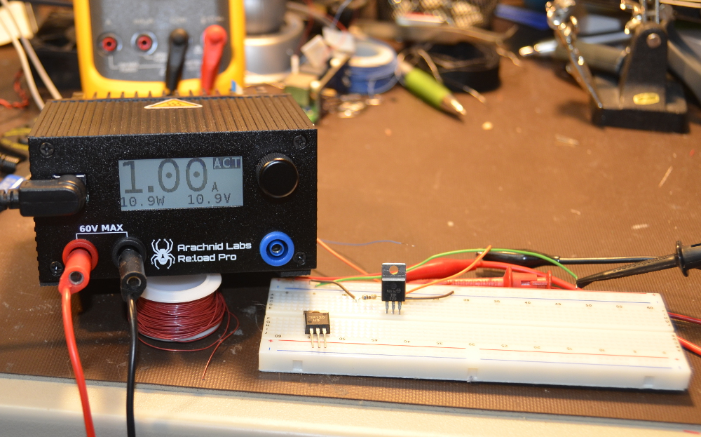
“Modern-day” replacements

Digital technology has taken over with this regard, and a device such as the one below can not only give the gain, but also the component details, identify legs, and much more:

I’ll be sticking with this one for the time being. Jaycar have discontinued the analyser shown above, but Altronics have the “Peak” unit which looks even more useful.

Conclusion

Well… that was fun. A lot of promise, however with a few details not taken care of the kit was just a bit off. Considering this was around twenty years old and possibly shop-soiled I can’t complain. For the record the good people at Altronics have a great line of kits. Full-sized images and a lot more information about the kit are available on flickr.

And while you’re here – are you interested in Arduino? Check out my new book “Arduino Workshop” from No Starch Press.

In the meanwhile have fun and keep checking into tronixstuff.com. Why not follow things on twitterGoogle+, subscribe  for email updates or RSS using the links on the right-hand column? And join our friendly Google Group – dedicated to the projects and related items on this website. Sign up – it’s free, helpful to each other –  and we can all learn something.

The post Old Kit Review – Silicon Chip Transistor Beta Tester appeared first on tronixstuff.

Tronixstuff 15 Dec 04:15

Glockentar: Epic Instrument Mashup

What happens when you want to play two instruments at the same time, but only have two hands? You let electronics do the work for you, of course.

Read the full article on MAKE

NPN Transistor Sketch (P2N2222AG) using PWM

We are now going to build a simple circuit to test out the P2N2222AG transistor in the sparkfun inventor's kit. You can also buy this transistor from RS-online.

Here are the components that you will need.
  • 1 x Arduino UNO
  • 1 x Breadboard
  • 1 x P2N2222AG transistor
  • 3 x LEDs  (1 x Red LED, 2 x Yellow LEDs)
  • 3 x 330 ohm Resistors
  • Wires to connect it all together.
Here is the Fritzing sketch:


We will use Pulse width modulation (PWM) to fade the LEDs in and out. 
Load the "Fading" example into the Arduino. (File>Examples>Analog>Fading)


I used this sketch to help me understand how electricity flowed through the transistor by disconnecting a wire here and there. I am not sure if this is advisable, so do this at your own risk. If you are an electrical engineer, feel free to comment. Please let me know if this is "risky" business.
I have had no formal training in electronics, so don't blame me if your arduino, or transistor blows up !
But from what I understand, I cannot see any harm in disconnecting wires with this particular circuit.
Please note, that I would disconnect the power to the arduino before modifying the wires.