Posts with «code» label

Arduino-based SocialChatter reads your Twitter feeds so you don't have to (video)

If you prefer reading your RSS feeds without the backlight, there's hardware for that, and if you'd prefer not reading your Twitter feeds at all, there's now hardware for that as well. Mix an Arduino Ethernet board, an Emic 2 Text-To-Speech Module and the knowhow to put them together, and you've got SocialChatter -- a neat little build that'll read your feeds aloud. The coding's already been done for you, and it's based on Adafruit's own Internet of Things printer sketch with a little bit of tinkering so nothing's lost in translation. If your eyes need a Twitter break and you've got the skills and kit to make it happen, head over to the source link for a how-to guide. Don't fill the requirements? Then jump past the break to hear SocialChatter's soothing voice without all the effort.

Continue reading Arduino-based SocialChatter reads your Twitter feeds so you don't have to (video)

Filed under: Misc. Gadgets, Internet

Arduino-based SocialChatter reads your Twitter feeds so you don't have to (video) originally appeared on Engadget on Thu, 16 Aug 2012 11:58:00 EST. Please see our terms for use of feeds.

Permalink | Email this | Comments

Arduino updates - I hate the new Arduino

When I started using Arduino, V0018 was the latest and greatest. Since then there have been about 7 updates and every time they update, more and more of my code fails to compile.

Since V1.0 and now V1.01 it seems the capital letter "F" cannot be used for a function name. This caused the error:
error: expected unqualified-id before 'reinterpret_cast'

read more

Let's Make Robots 06 Aug 05:18
arduino  avr  code  compatibility  error  strange  update  

Grove OLED 96x96 Slideshow

This project makes use of the Grove OLED 96x96 display to present a mini-slideshow.  Pictures on your computer are transferred to the OLED via a Processing script, and will cycle through them as many times as you choose.

Video:


Parts required:


Software required:


Sketch:


Arduino Sketch:
 1
2
3
4
5
6
7
8
9
10
11
12
13
14
15
16
17
18
19
20
21
22
23
24
25
26
27
28
29
30
31
32
33
34
35
36
37
38
39
40
41
42
43
44
45
46
47
48
49
50
51
52
53
54
55
56
57
58
59
60
61
62
63
// OLED Slideshow: Arduino Sketch written by ScottC 21/07/2012

#include <Wire.h>
#include <SeeedGrayOLED.h> //From http://garden.seeedstudio.com/images/c/c4/SeeedGrayOLED.zip
#include <avr/pgmspace.h>

int counter=0;

void setup()
{
//Allow communication to OLED
Wire.begin();

//Allow Serial communication between Freetronics Eleven and Computer
Serial.begin(28800);

//Initialise the OLED
SeeedGrayOled.init();
//Clear the OLED display
SeeedGrayOled.clearDisplay();
//Set to vertical mode - horizontal mode doesn't work with this example
SeeedGrayOled.setVerticalMode();

}

void loop(){
//Listen for Serial comunication
while (Serial.available()>0) {
// Read data and send directly to the OLED
sendMyData(Serial.read());
counter++;

//When counter reaches 4608 pixels, the picture is complete.
if(counter>4607){
//Insert delay to allow viewing of picture.
delay(4000);
Serial.println("End of Transmission");

//Reset the counter for the next picture
counter=0;
}
}
}

// This function was adapted from the SEEED Gray OLED driver so that
// character bytes could be sent directly to the OLED.
void sendMyData(unsigned char Data){
Wire.beginTransmission(SeeedGrayOLED_Address); // begin I2C transmission
Wire.send(SeeedGrayOLED_Data_Mode); // data mode
Wire.send(Data);
Wire.endTransmission();
}


// This function was adapted from the SEEED Gray OLED driver so that
// commands could be sent directly to the OLED.
// NOT USED IN THIS EXAMPLE ***********************
void sendMyCommand(unsigned char Cmd){
Wire.beginTransmission(SeeedGrayOLED_Address); // begin I2C communication
Wire.send(SeeedGrayOLED_Command_Mode); // Set OLED Command mode
Wire.send(Cmd);
Wire.endTransmission(); // End I2C communication
}


Processing Sketch:
  1
2
3
4
5
6
7
8
9
10
11
12
13
14
15
16
17
18
19
20
21
22
23
24
25
26
27
28
29
30
31
32
33
34
35
36
37
38
39
40
41
42
43
44
45
46
47
48
49
50
51
52
53
54
55
56
57
58
59
60
61
62
63
64
65
66
67
68
69
70
71
72
73
74
75
76
77
78
79
80
81
82
83
84
85
86
87
88
89
90
91
92
93
94
95
96
97
98
99
100
101
102
103
104
105
106
107
108
109
110
111
112
113
114
115
116
117
118
119
120
121
122
123
124
125
126
127
128
129
130
/* OLED Slideshow: Processing Sketch Written by ScottC 21/7/2012 

References:
Getting Pixels: http://www.learningprocessing.com/examples/chapter-15/example-15-7/
Greyscale conversion = http://www.openprocessing.org/sketch/60336
*/


import processing.serial.*; /* Needed for Serial Communication */

/* Global variables */
Serial comPort;
String [] comPortList;
String comPortString;
PImage img;
char[] tempGrey=new char[4609];
int startOffset=0;
ArrayList picNames;
int curLoop=1;
int totalPics=0;
int curPicNum=0;
boolean toggleSend=true;
boolean sendBouncer=true;

//Change maxLoops to a number > 1 if you want the pictures to loop.
int maxLoops=1;


void setup() {
//The size of the display is critical (must match the OLED)
size(96, 96);
//setup Serial
comPortList = Serial.list();
if(comPortList.length>0){
//baud rates greater than 28800 may produce unexpected results
comPort = new Serial(this, comPortList[0], 28800);
comPort.bufferUntil('\n');
} else{
println("NO COM PORTS AVAILABLE");
}

//Create an Array of pictures
picNames=new ArrayList();
picNames.add("Picture1.bmp");
picNames.add("Picture2.bmp");
picNames.add("Picture3.bmp");
picNames.add("Picture4.bmp");
// for more pictures just keep adding them to the list.
//The actual pictures must be located in the data folder of this project.
//Select Sketch/Add File to add the files to this folder.
//Make sure that the name of pictures match the names above.

//Get the total number of pictures added
totalPics=picNames.size();
}

void draw(){
if(toggleSend && sendBouncer){

// Debugging code: print("STARTED:");
// Debugging code: println(picNames.get(curPicNum));

sendImage((String)picNames.get(curPicNum)); //Send the picture to the OLED
toggleSend=false; //temporarily stop sending any more pictures until authorised
curPicNum++; //increment in preparation for the next picture

if(curPicNum==totalPics){
curPicNum=0; //go back to the first picture
curLoop++; //increment the loop counter
}
if(curLoop>maxLoops){
sendBouncer=false; //Stop any further looping
println("ANIMATION COMPLETE");
}
}
}


void sendImage(String imgName){
img = loadImage(imgName);
image(img,0,0,width,height);
loadPixels();
int counter=0;
for (int x = 0; x < width; x=x+2) {
for (int y = 0; y < height; y++) {
counter++;
int PixLoc = x + y*height; // this reads down then across2.
//Left pixel nibble
int Pix1=(round((red(pixels[PixLoc])*0.222+green(pixels[PixLoc])*0.707+blue(pixels[PixLoc])*0.071)))/16;
//Right pixel nibble
int Pix2=(round((red(pixels[PixLoc+1])*0.222+green(pixels[PixLoc+1])*0.707+blue(pixels[PixLoc+1])*0.071)))/16;
//Shift the byte <<4 for the left pixel nibble
int PixShift1=Pix1<<4;
//Combine both nibbles to form a byte
int PixFin = PixShift1+Pix2;
byte PixByteFin=byte(PixFin);
//Assign this byte to the tempGrey array
tempGrey[counter] = char(PixByteFin);
}
}
sendSerial(tempGrey); //Send the image data through the Serial COM Port/
}


//This function will send the byte/Char array to the Freetronics
//Eleven or Arduino.
void sendSerial(char[] Data){
for(int i=0; i<4608; i++){
//Needs an offset to get picture to align to screen properly
//only needs to do this once.
if(startOffset==0){
i=i+6;
startOffset++;
}
//Send the picture data to the Freetronics Eleven / Arduino
comPort.write(Data[i]);
}
}


//This function will wait for a response from the Freetronics
//Eleven or Arduino before sending any further pictures.
void serialEvent (Serial myPort) {
// get the ASCII string:
String inString = myPort.readStringUntil('\n');
if (inString != null) {
println(inString);
toggleSend=true; // Allow the next picture to be sent
}
}


Please note: that you must use the Arduino IDE version 023 until Seeed Studio update their driver for this OLED. Their current driver is not compatible with later versions of Arduino IDE.


Simple Arduino Serial Communication (Part 2)

In Stages 1 to 5 , we experimented with the Serial Monitor on the Arduino IDE to transmit data to the Arduino and receive data from the Arduino. We performed simple Serial communication of data in both directions.

We then moved from transmitting a String of characters to the more difficult task of transmitting a double or a float.

Finally, we used the Serial monitor to receive sensor data from our Arduino, and played with a couple of Arduino functions.

We will now look at replacing the Serial Monitor with a much more exciting program such as "Processing" which is a free Open Source program that interfaces very easily with the Arduino. It can be downloaded here.

We will use a few processing scripts to bring our Arduino Sensor projects to life !


Stage 6: A simple Processing Sketch: BLINK


Arduino IDE vs Processing IDE


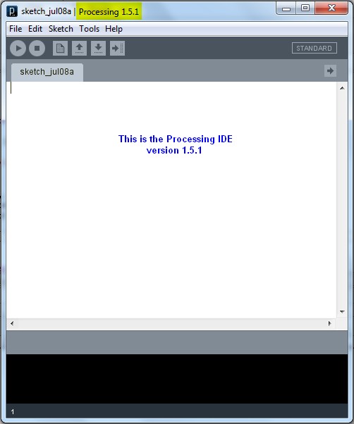
While the processing IDE looks very similar to the Arduino IDE, it is important that you realise that the Processing sketch will run on your computer, and NOT on the Arduino. In fact, you do not even need an Arduino to run a Processing sketch. And that is exactly what we are going to do: Run a Processing sketch without an Arduino.

Parts Required


  • A computer
  • Processing IDE

  • Once you have downloaded and installed the Processing IDE onto your computer, open the program and copy the following sketch into it, and then press the play button. This is different from the Arduino IDE, in that we do not have to upload it to anything, as it will be running from the computer.

    Processing Sketch


    1
    2
    3
    4
    5
    6
    7
    8
    9
    10
    11
    12
    13
    14
    15
    16
    17
    18
    19
    20
    21
    22
    23
    24
    25
    26
    27
    28
    29
    30
    31
    32
    33
    34
    35
    36
    37
    38
    39
    40
    41
    42

    /* Stage 6: Simple Processing Blink Sketch
    Created by ScottC on the 8/7/2012
    http://arduinobasics.blogspot.com/ */


    /* Setup the color variables and switching mechanism */
    color Red=color(255,0,0);
    color White=color(255,255,255);
    Boolean mySwitch=true;


    /* The setup function only runs once */

    void setup(){
    /* Set the size of the window using size(width,height) */
    size(400,400);
    }

    /* The draw function will refresh screen only after it has
    processed all functions within it. Which is why I needed
    a switch to swap between the red and the white background
    The draw() function will run in an endless loop. */

    void draw(){
    blink(mySwitch); //Call to blink function
    delay(2000); //The blinking speed (2 secs)
    }


    /* The blink function switches the background from red to white
    or from white to red. */

    void blink(Boolean swtch){
    /* If swtch is true, make the background red
    otherwise make it white */
    if(swtch){
    background(Red); // red
    }else {
    background(White); // white
    }
    /* Toggle mySwitch between true and false */
    mySwitch=!mySwitch;
    }


    Things to Try


    1. Change the White background to a black background

    2. Insert on line 9: color Black=color(0,0,0);
      Change line 38: background(Black);


    3. Increase the blink rate to 1 second

    4. Change line 25: delay(1000);
      WARNING : Do not increase the speed too much, it may cause an epileptic fit.


    Now that wasn't too hard I hope.
    And if you want a very good site to learn Processing have a look at these


  • The official Processing reference library
  • Official Processing Tutorials
  • Getting started with Processing
  • Daniel Shiffman's Processing Examples and Tutorials


  • Stage 7: Arduino and Processing Unite.


    So how do we get our Arduino to interface with our computer? Well, if the Serial Monitor on the Arduino IDE is not good enough, then you could use any program that is capable of Serial communication. Fortunately, Processing is one of those programs, but you could use C++, Java, Python, Microsoft Excel (using VBA), VB.Net, Gobetwino or some other programming language.

    Two programs will be created: One will be uploaded to the Arduino using the Arduino IDE, and the other will run on the computer. In this example we will use Processing as the program that will run on the computer.

    Enter the following sketch into the Arduino IDE and upload it to the Arduino. It serves to generate a random number between 0 and 400 every 200msec and will send it to the computer via the USB cable , using Serial communication.

    Arduino Sketch


     1
    2
    3
    4
    5
    6
    7
    8
    9
    10
    11
    12
    13
    /* Stage 7: Simple Arduino Serial Random Number Generator
    Written by ScottC on 09/07/2012
    http://arduinobasics.blogspot.com/
    */


    void setup(){
    Serial.begin(9600); //Begin Serial Communication
    }

    void loop(){
    Serial.println(random(1,1000)); //Send Random # to computer
    delay(200); //Delay 200ms between values.
    }


    Instructions

    Once the program has been uploaded to the Arduino, we will want to make sure that it is performing to expectations before moving onto the Processing script.

    Open the Arduino Serial Monitor and make sure that you see a bunch of random numbers scrolling down the page. If not, then go back over your code and try again. Once you see the random numbers, then it is safe to move on to the next step.


    Processing

    The following Processing script will display the Random numbers being sent from the Arduino in the Processing IDE debug window. This particular script is very much like a simplified Arduino Serial Monitor, and it will show you that the Processing Script is successfully communicating with the Arduino.


    Processing Sketch

     1
    2
    3
    4
    5
    6
    7
    8
    9
    10
    11
    12
    13
    14
    15
    16
    17
    18
    19
    20
    21
    22
    23
    24
    25
    26
    27
    28
    29
    30
    31
    32
    33
    34
    35
    36
    37
    38
    39
    40
    41
    42
    43
    44
    45
    46
    47
    48
    49
    50
    51
    52
    53
    54
    /* Some of the Serial code was adapted from Tom Igoe's example
    on this site: http://processing.org/reference/libraries/serial/Serial.html
    and http://processing.org/reference/libraries/serial/serialEvent_.html

    The rest of this Processing code was written by ScottC on 11/07/2012
    http://arduinobasics.blogspot.com/
    */


    import processing.serial.*; /* Needed for Serial Communication */

    /* Global variables */
    Serial comPort;
    String [] comPortList;
    String comPortString;

    /*--------------------------------------------------*/

    void setup(){
    size(100,100); /* Set the size of the window */
    background(0); /* Set the background to black */


    /* Get the available com ports. If there is at least one
    com port available, then start communicating on it.
    If there are more than one com ports available, we will
    only open the first one (i.e. comPortList[0])
    The bufferUntil('\n'); statement will generate a serial Event
    when it reads a carriage return */

    comPortList = Serial.list();
    if(comPortList.length>0){
    comPort = new Serial(this, comPortList[0], 9600);
    comPort.bufferUntil('\n');
    }
    }

    /*--------------------------------------------------*/

    void draw(){
    /* The serialEvent function will update the display */
    }

    /*--------------------------------------------------*/

    void serialEvent(Serial cPort){
    comPortString = cPort.readStringUntil('\n');
    if(comPortString != null) {
    comPortString=trim(comPortString);

    /* Print to the Debug screen in Processing IDE */
    println(comPortString);
    }
    }


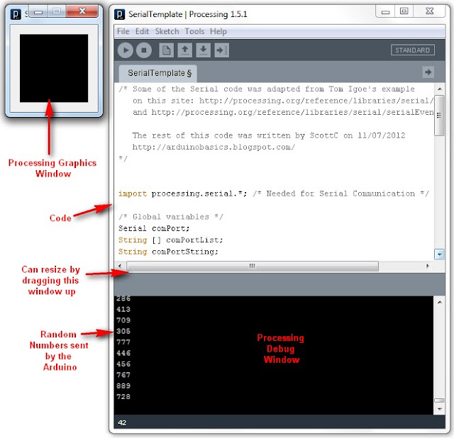
    When you run the Processing script, a little black window will appear. This is the Processing Graphics window, which is normally where all the action takes place. However in the sketch above, this window does nothing. Instead we make use of the black Debug window which is part of the Processing IDE (below the code window). If everything went to plan, you should see random numbers scrolling down in a similar fashion to the Arduino Serial monitor. Here is an example of what it should look like.


    Things to Try


    1. If you are having problems with COM port selection. Then have a look at the COM port being used on the Arduino IDE to upload sketches to the Arduino. Processing generally uses the same COM port. So make sure to close the Arduino Serial Monitor before running the Processing Sketches.


    The image above shows that I am currently using COM PORT 6 on my computer to upload Arduino Sketches. In the Processing sketch on line 32-35, I had this code:

    32
    33
    34
    35
      if(comPortList.length>0){
    comPort = new Serial(this, comPortList[0], 9600);
    comPort.bufferUntil('\n');
    }


    We can change line 33 to get Processing to use COM port 6 exclusively. We do this by replacing comPortList[0] with "COM6", as seen below:

    32
    33
    34
    35
      if(comPortList.length>0){
    comPort = new Serial(this, "COM6", 9600);
    comPort.bufferUntil('\n');
    }


    Stage 8 : Arduino and Processing - Random Font Project


    Arduino and Processing are speaking to each other by this stage, and we will keep our original Arduino Sketch to produce random numbers for us. Sure, we don't actually need the Arduino to do this for us, because Processing is more than capable of doing this itself, but we are building up towards an interactive sketch, so lets just go through the motions.

    Just in case your mouse scroll wheel doesn't move upwards, here is the Arduino Sketch again:

    Arduino Sketch


     1
    2
    3
    4
    5
    6
    7
    8
    9
    10
    11
    12
    13
    /* Stage 8: Simple Arduino Serial Random Number Generator
    Written by ScottC on 09/07/2012
    http://arduinobasics.blogspot.com/
    */


    void setup(){
    Serial.begin(9600); //Begin Serial Communication
    }

    void loop(){
    Serial.println(random(1,1000)); //Send Random # to computer
    delay(100); //Delay 100ms between values.
    }


    Upload the Arduino sketch to the Arduino, and then put the following code into the Processing IDE:

    Processing Sketch


    The output of this sketch should look something like this:


    For stages 9 and above: Click Here


    Simple Arduino Serial Communication

    This Tutorial is progressive and will be updated from time to time. The goal is to start from a very basic form of Arduino Serial communication, and progressively add or improve components so that we can ultimately transmit data from one computer to another using an XBee.
    Please note: I am not an expert, but am happy to share what I have learned. The Arduino forums are a great place to ask questions, feel free to link to this blog (if required).

    Let us begin.


    Stage 1: ECHO ECHO                                                                                    


    Parts Required:

    • Computer
    • USB cable
    • Arduino UNO (or equivalent)
    • Arduino IDE

    The following code will make the Arduino ECHO anything you send to it. Therefore, if you type a 3, the Arduino will send back a 3. If you type a letter F, the Arduino will send back a letter F. 
    Enter the following code into your Arduino IDE and upload it to your Arduino.


    Arduino Sketch


     1
    2
    3
    4
    5
    6
    7
    8
    9
    10
    11
    12
    13
    14
    15
    16
    17
    18
    19
    20
    /* Simple Serial ECHO script : Written by ScottC 03/07/2012 */

    /* Use a variable called byteRead to temporarily store
    the data coming from the computer */
    byte byteRead;

    void setup() {
    // Turn the Serial Protocol ON
    Serial.begin(9600);
    }

    void loop() {
    /* check if data has been sent from the computer: */
    if (Serial.available()) {
    /* read the most recent byte */
    byteRead = Serial.read();
    /*ECHO the value that was read, back to the serial port. */
    Serial.write(byteRead);
    }
    }
    The above code was formatted using this site


    Instructions

    1. Once the Arduino sketch has been uploaded to the Arduino. Open the Serial monitor, which looks like a magnifying glass at the top right section of the Arduino IDE. Please note, that you need to keep the USB connected to the Arduino during this process, as the USB cable is your communication link between your computer and the Arduino.


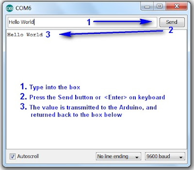
    2. Type anything into the top box of the Serial Monitor and press <Enter> on your keyboard. This will send a series of bytes to the Arduino. The Arduino will respond by sending back your typed message in the larger textbox.


    3. Please note that we are using Serial.write(byteRead); on line 18 to get the Arduino to ECHO the message back to you on your computer. 


    Things to Try 

    1. Delete lines 16 to 18, and replace them with the following line :

                   Serial.write(Serial.read());

    This essentially eliminates the byteRead variable in the sketch above. But we will be using it later on, so once you have tested it out, put the code back together as originally displayed.


    --------------------------------------------------------------------
    2. Replace line 18 with a Serial.println instead of Serial.write

                   Serial.println(byteRead);

    Once uploaded, type 1 <enter> 2 <enter> 3 <enter>  into the Serial Monitor.
    You should see:

    49
    50
    51

    Serial.print and Serial.println will send back the actual ASCII code, whereas Serial.write will send back the actual text. See ASCII codes for more information.


    --------------------------------------------------------------------
    3. Try typing in numbers like 1.5  or  2.003  or  -15.6 into the Serial Monitor using Serial.write and Serial.print or Serial.println commands as described before.

    You will notice that the decimal point transmits as a number using Serial.print  or Serial.println, and will transmit as a decimal point when using Serial.write


    STAGE 2: Delimiters                                                                                


    How do you handle 2 or more numbers when sending or receiving?
    Let us say that you have number pairs that you want the Arduino to interpret. How do you separate the numbers? The answer is Delimiters.
    You may be familiar with CSV (comma separated value) files, where each field is separated by a comma (,). The comma is a useful way of separating or grouping information.

    Lets say you have the following stream of numbers:
    12345678910

    How will your Arduino know if this is a single number, or a series of numbers?
    Eg:

    12,34,56,78,91,0
    123,456,78,910
    1,2,3,4,5,6,7,8,9,10
    12345678910

    The comma delimiters help to identify how the numbers should be interpreted.

     In the echo example in Stage 1 above, you would have noticed that when we used Serial.print(byteRead); that the values displayed one after another in a similar fashion to 12345678910.

    You would have also noticed that Serial.println(byteRead); provided a line break between each value sent. And depending on the numbers sent, it could have looked like this:
    12
    34
    56
    78
    91
    0

    The Serial.println() function essentially uses a line feed to separate the values being sent. This line break can be used as a delimiter, but we will look at that later on. For now we will concentrate on using a comma (,).

    We will now get the Arduino to "listen" for the comma to help it identify a new number.
    According to the ASCII code site, a comma is equal to byte code 44. So when the Arduino reads a byte code that is equal to 44, we will get it to print a line feed.


    Enter the following sketch into your Arduino IDE and upload it to your Arduino.

    Arduino Sketch


     1
    2
    3
    4
    5
    6
    7
    8
    9
    10
    11
    12
    13
    14
    15
    16
    17
    18
    19
    20
    21
    22
    23
    24
    25
    26
    27
    /* Simple Serial ECHO script : Written by ScottC 04/07/2012 */
    /* Stage 2 : Delimiters */

    /* Use a variable called byteRead to temporarily store
    the data coming from the computer */
    byte byteRead;

    void setup() {
    // Turn the Serial Protocol ON
    Serial.begin(9600);
    }

    void loop() {
    /* check if data has been sent from the computer: */
    if (Serial.available()) {
    /* read the most recent byte */
    byteRead = Serial.read();

    /*Listen for a comma which equals byte code # 44 */
    if(byteRead==44){
    Serial.println();
    }else{
    /*ECHO the value that was read, back to the serial port. */
    Serial.write(byteRead);
    }
    }
    }
    The above code was formatted using this site


    Instructions

    1. Once the code has been uploaded to the Arduino, open the Serial Monitor once again and type the following sequence of numbers:

    1 <enter>  2 <enter> 3 <enter>

    You should see the Serial monitor display the following number:    123


    --------------------------------------------------------------------
    2. While still in the serial monitor, type the following:

    , <enter> 1 <enter> , <enter> 2 <enter> , <enter> 3 <enter> ,

    Please note the commas between each numerical entry. You should now see a pattern like this:
    1
    2
    3


    --------------------------------------------------------------------
    3. While still in the serial monitor, type the following:

    12,23,34,45, <enter>

    Please note the commas between each numerical entry. You should now see a pattern like this:
    12
    23
    34
    45

    You will notice that the commas have been replaced by line feeds, and each number should display on a new line.


    --------------------------------------------------------------------
    4. While still in the serial monitor, type the following:

    1,,2,,3, <enter>

    You should see the following pattern:
    1

    2

    3


    So hopefully that explains the concept of delimiters and how they can be used to separate a stream of numbers, no matter how long it takes to get to the Arduino. We used an IF-statement to listen for the comma, but we could have used any other delimiter provided we knew the byte code.

    We did not identify how to send delimiters FROM the Arduino, but we will get to that I promise. It is not that hard, and uses a similar principle. I am sure you can work it out, if not, stay tuned.


    STAGE 3: Arduino Maths: Simple addition                                                  


    In this stage, we are going to get the Arduino to do simple maths. We will send it two integers (or whole numbers), and the Arduino will do the hard work and send us the answer in no time at all.
    This might seem like a simple task, but when you send a number like 27 to the Arduino, it does not receive the number 27. It receives 2 and then 7 in byte form. In other words, the Arduino will see the byte codes 50 and then 55 as per the ASCII table on this page.

    One way to convert this byte code back to a 2 and a 7 is to subtract 48 from each byte received, providing the byte is in the range 48 to 57 inclusive (which equates to the numbers 0-9).
    We are not done yet. We then need to join these numbers to make 27.

    Step1: Subtract 48 from the bytes received, only if the bytes are in the range 48 to 57.
                     Example:    50 - 48 = 2
                                        55- 48 = 7

    Step2: Multiply the previous number by 10, before adding the most recent byte received.
                     Example:   (2 x 10) + 7 = 27

    If we have a number like 1928, then we would create this number using the following calculation
                                       1 =                         1
                       (1 x 10) + 9 =    10 + 9   =   19
                    (19 x 10) + 2  = 190 + 2   =  192
                  (192 x 10) + 8  = 1920 + 8 = 1928

    Step3: Use a "+" sign as a delimiter so that the Arduino can move onto the Second number

    Step4:  Capture the second number as per Step2. An "=" sign will tell the Arduino that it has reached the end of the second number, and to proceed to step 5.

    Step5:  Add the 2 numbers together and send back the answer.


    The following code will carry out the 5 steps above.
    Enter the following sketch into your Arduino IDE and upload it to your Arduino.

    Arduino Sketch


     1
    2
    3
    4
    5
    6
    7
    8
    9
    10
    11
    12
    13
    14
    15
    16
    17
    18
    19
    20
    21
    22
    23
    24
    25
    26
    27
    28
    29
    30
    31
    32
    33
    34
    35
    36
    37
    38
    39
    40
    41
    42
    43
    44
    45
    46
    47
    48
    49
    50
    51
    52
    53
    54
    55
    56
    57
    58
    59
    60
    61
    62
    63
    64
    /* Simple Serial ECHO script : Written by ScottC 05/07/2012 */
    /* Stage 3: Arduino Maths: Simple Addition */

    /* Global variables needed for programming workflow
    byteRead: holds the value being read from the COM port
    num1: holds the entire first number
    num2: holds the entire second number
    answer: holds the sum of num1 and num2
    mySwitch: enables the switch between num1 and num2 */

    byte byteRead;
    long num1, num2,answer;
    boolean mySwitch=false;

    void setup() {
    /* Turn the Serial Protocol ON and
    initialise num1 and num2 variables.*/
    Serial.begin(9600);
    num1=0;
    num2=0;
    }

    void loop() {
    /* check if data has been sent from the computer: */
    while (Serial.available()) {
    /* read the most recent byte */
    byteRead = Serial.read();

    //listen for numbers between 0-9
    if(byteRead>47 && byteRead<58){
    //number found

    /* If mySwitch is true, then populate the num1 variable
    otherwise populate the num2 variable*/
    if<!mySwitch)><br /> num1=(num1*10)+(byteRead-48);<br /> }<span>else</span>{<br /> num2=(num2*10)+(byteRead-48);<br /> }<br /> }<br /> <br /> <span>/*Listen for an equal sign (byte code 61) </span><br /><span> to calculate the answer and send it back to the</span><br /><span> serial monitor screen*/</span><br /> <span>if</span>(byteRead==61){<br /> answer=num1+num2;<br /> Serial.print(num1);<br /> Serial.print(<span>"+"</span>);<br /> Serial.print(num2);<br /> Serial.print(<span>"="</span>);<br /> Serial.println(answer);<br /> <br /> <span>/* Reset the variables for the next round */</span><br /> num1=0;<br /> num2=0;<br /> mySwitch=<span>false</span>;<br /> <br /> <span>/* Listen for the addition sign (byte code 43). This is</span><br /><span> used as a delimiter to help define num1 from num2 */</span> <br /> }<span>else</span> <span>if</span> (byteRead==43){<br /> mySwitch=<span>true</span>;<br /> }<br /> }<br />}<br /></pre></td></tr></tbody></table></div><br /><span>The above code was formatted using <a href="http://hilite.me/">this site</a></span><br /><br /><br /><h3> <u>Instructions</u></h3><br /><b>1.</b> Once the code has been uploaded to the Arduino, open the Serial Monitor once again and type the following sequence:<br /><br />         <span>1+2=   <enter></span><br /><br />You should get the following message sent back to Serial Monitor<br /><br />        <span> 1+2=3</span><br /><br /><br /><br /><h3> <b><u>Things to Try</u></b></h3><b>1.</b>   Enter this sequence: <br />              <span>10   <enter></span><br /><span>               +   <enter></span><br /><span>              10  <enter></span><br /><span>               =   <enter></span><br /><br />       Result:     <span>10+10=20</span><br /><br /><span>--------------------------------------------------------------------</span><br /><b>2. </b>  Enter this sequence:<br />            <span> 10  <enter></span><br /><span>             20  <enter></span><br /><span>             +5= <enter></span><br /><br /><br />      Result:  <span> 1020+5=1025</span><br /><br /><br /><br /><br /><span>--------------------------------------------------------------------</span><br /><b>3.</b>   Enter this sequence:<br />            <span> 10+20+30=   <enter></span><br /><br /><br />      Result:    <span>10+2030=2040</span><br /><br />I have specifically written this script to add <b>two</b> whole numbers together. If you start to introduce more complicated calculations, the results become unpredictable.<br /><br /><span>--------------------------------------------------------------------</span><br /><b>4.</b>    Enter this sequence:<br />           <span>1.2+1.0=    <enter></span><br /><br />      Result: <span>12+10=22</span><br /><br />Once again, I have only designed this script to handle whole numbers. Therefore, decimal points are ignored.<br /><br /><span>--------------------------------------------------------------------</span><br /><b>5.</b>  Enter this sequence:<br />         <span> -5 + 10=     <enter></span><br /><br /><br />     Result:    <span>5+10=15</span><br /><br /><br />This script ignores the negative sign, and treats the -5 as a positive 5.<br /><br /><br /><div>I have done this on purpose. I wanted to show you how the Arduino reads numbers from the com port, and how easy it is to exclude vital functionality in your code. I have kept this script simple, however, if you wanted to, you could make the Arduino deal with each of the above situations and more.  Multiplication, division and subtraction is handled in the same way. </div><br />This is the last thing I want you to try before we go to the next stage:<br /><br />6. Enter this sequence:<br />           <span>2147483646+1=  <enter></span>           Result:  <span>2147483646+1=2147483647</span><br />          <span> 2147483647+1=  <enter></span>           Result: <span>2147483647+1=</span><span>-</span><span>2147483648</span><br /><br /><br />Note that the maximum size of a "long" number is 2147483647. If you add one to this number, the result is equal to the minimum size of a "long" which is -2147483648.<br /><br /><br /><br /><br /><h3> <b><span><span>STAGE 4:  Sending doubles to Arduino</span> : <span>The double doubler</span>             </span></b></h3><div>Now we get to some tricky business. Sending and receiving Doubles (to and from) the Arduino.<br /><br />Up until now, I have tried to keep it simple using whole numbers, but there will come a time when you will want to send a fraction of a number through the Serial line.</div><div>To test our program, we will want to send a very small number to the Arduino, multiply the number by 2, and return it back.</div><div><br /></div><div>Our final test is to try a number like :  <b>0.000001</b></div><div>             and then a number like:<b>   123.321</b></div><div><br /></div><div><br /><b><span>IMPORTANT NOTE</span></b>:   When the Arduino sends a float or a double through the COM port using Serial.print() or Serial.println(), it will automatically send the number to 2 decimal places.<br />A number like 1.2345 will appear as 1.23,   and a number like 1.9996 will appear as 2.00<br />To demonstrate this, we will get the Arduino to send these floats/doubles to the Serial Monitor.<br /><br /><br /><div>Enter the following sketch into your Arduino IDE and upload it to your Arduino.</div><div><br /></div><h3> <u>Arduino Sketch</u></h3><br /><div><table><tbody><tr><td><pre><span><span> 1<br /> 2<br /> 3<br /> 4<br /> 5<br /> 6<br /> 7<br /> 8<br /> 9<br />10<br />11<br />12<br />13<br />14<br />15<br />16<br />17<br />18<br />19<br />20<br />21<br />22<br />23<br />24<br />25<br />26<br />27<br />28</span></span></pre></td><td><pre><span>/* Stage 4: Simple Transmission of a Double</span><br /><span> Written by ScottC on 7/7/2012 */</span><br /><br /><span>/* Declare the doubles that will be sent to the Serial Monitor */</span><br /> <span>double</span> myDub1, myDub2;<br /><br /><span>/* This part of the program only runs ONCE */</span><br /><br /> <span>void</span> setup(){<br /><br /> <span>/* Turn ON Serial Communication */</span><br /> Serial.begin(9600);<br /> <br /> <span>/* Assign a value 1.2345 and 1.9996 to the Doubles being sent */</span><br /> myDub1=1.2345;<br /> myDub2=1.9996;<br /> <br /> <span>/*Send the values to the Serial Monitor */</span><br /> Serial.print(<span>"myDub1 (1.2345) : "</span>);<br /> Serial.println(myDub1);<br /> Serial.print(<span>"myDub2 (1.9996) : "</span>);<br /> Serial.println(myDub2);<br /> }<br /><br /><br /> <span>void</span> loop(){<br /> <span>//Loop does nothing</span><br /> }<br /></pre></td></tr></tbody></table></div><span>The above code was formatted using </span><a href="http://hilite.me/">this site</a><br /><br />When you open the Serial monitor (after you have uploaded the sketch above), you will notice the following output:<br /><br /><br />         <span> myDub1 (1.2345) :</span> <span>1.23</span><br />         <span> myDub2 (1.9996) :</span> <span>2.00</span><br /><div><br /></div><br /><br />The <span>blue text</span> represents the string (or array of characters) being sent using lines 19 and 21.<br />The <span>red text</span> represents the actual double being sent using lines 20 and 22.<br /><br />You will notice that myDub2 rounds to 2.00.  This may or may not be what you want.<br />If you wish to increase the number of decimal places, then you will need to change lines 20 and 22 to the following:<br /><br /><span><span>20         Serial.println(myDub1,</span><span>4</span><span>)</span>;</span><br /><span><span>22         Serial.println(myDub2,</span><span>4</span><span>);</span></span><br /><br />The number 4 highlighted in red, indicates the number of decimal places you wish to send.<br />Try it ! And try changing this number to something bigger or smaller.<br /><br />---------------------------------------------------------------------------------------------------<br />Ok - now that we understand this little Serial.print(double,decimals) trick, we will now get the Arduino to echo back a Double.<br /><br />Before we jump in, perhaps we should try and map out our strategy. For this we will choose a simple decimal to make it easier. So in this example, we will choose <b>0.1</b></div><div>Once we get this working, we can then do our final test (as mentioned above).</div><div><br /></div><div>If we send 0.1 to the Arduino, it will read the following byte code</div><div><br /></div><div>48                    0</div><div>46                    .</div><div>49                    1</div><div><br /></div><div>We can use the decimal point as a delimiter.<br />We will use the following 5 steps to echo the double back to the Serial Monitor:</div><div><br /></div><div><b><span>Step1</span>:</b> Arduino collects all numbers before the decimal point using the same technique as in Stage3.<br /><br /></div><div><b><span>Step2</span>: </b>When the Arduino receives byte code 46, it will go into decimal mode.<br /><br /></div><div><b><span>Step3</span>:</b> The Arduino will collect numbers after the decimal point using a similar technique to step1.<br /><br /></div><div><b><span>Step4</span>:</b> Use maths to create the double, and then multiply it by 2<br /><br /></div><div><b><span>Step5</span>:</b> Display the doubled Double value in the Serial monitor.</div><div><br /></div><div><br /></div><div><br /><div>Enter the following sketch into your Arduino IDE and upload it to your Arduino.</div><div><br /></div><h3> <u>Arduino Sketch</u></h3></div><div><br /></div><div><table><tbody><tr><td><pre><span><span> 1<br /> 2<br /> 3<br /> 4<br /> 5<br /> 6<br /> 7<br /> 8<br /> 9<br />10<br />11<br />12<br />13<br />14<br />15<br />16<br />17<br />18<br />19<br />20<br />21<br />22<br />23<br />24<br />25<br />26<br />27<br />28<br />29<br />30<br />31<br />32<br />33<br />34<br />35<br />36<br />37<br />38<br />39<br />40<br />41<br />42<br />43<br />44<br />45<br />46<br />47<br />48<br />49<br />50<br />51<br />52<br />53<br />54<br />55<br />56<br />57<br />58<br />59<br />60<br />61<br />62<br />63<br />64<br />65<br />66<br />67<br />68<br />69<br />70<br />71<br />72<br />73<br />74<br />75<br />76<br />77<br />78<br />79<br />80<br />81<br />82<br />83<br />84<br />85</span></span></pre></td><td><pre><span>/* Simple Serial ECHO script : Written by ScottC 06/07/2012 */</span><br /><span>/* Stage 4: Double doubler */</span><br /><br /><span>/* Global variables needed for programming workflow</span><br /><span> ------------------------------------------------------</span><br /><span> byteRead: holds the value being read from the COM port</span><br /><span> num1: holds the number before the decimal point</span><br /><span> num2: holds the number after the decimal point</span><br /><span> complNum: holds the complete number (before multiplation)</span><br /><span> answer: holds the final value after multiplication</span><br /><span> counter: is used to convert num2 to the number after the decimal</span><br /><span> numOfDec: counts the numbers after the decimal point</span><br /><span> mySwitch: enables the switch between num1 and num2 */</span><br /> <br /> byte byteRead;<br /> <span>double</span> num1, num2;<br /> <span>double</span> complNum,answer,counter;<br /> <span>int</span> numOfDec;<br /> boolean mySwitch=<span>false</span>;<br /><br /><br /> <span>void</span> setup() { <br /><span>/* Turn the Serial Protocol ON and </span><br /><span> initialise num1 and num2 variables.*/</span><br /> Serial.begin(9600);<br /> num1=0;<br /> num2=0;<br /> complNum=0;<br /> counter=1;<br /> numOfDec=0;<br /> }<br /><br /> <span>void</span> loop() {<br /><span>/* check if data has been sent from the computer: */</span><br /> <span>while</span> (Serial.available()) {<br /> <span>/* read the most recent byte */</span><br /> byteRead = Serial.read();<br /> <br /> <span>//listen for numbers between 0-9</span><br /> <span>if</span>(byteRead>47 && byteRead<58){<br /> <span>//number found</span><br /> <br /> <span>/* If mySwitch is true, then populate the num1 variable</span><br /><span> otherwise populate the num2 variable*/</span><br /> <span>if</span><!mySwitch)><br /> num1=(num1*10)+(byteRead-48);<br /> }<span>else</span>{<br /> num2=(num2*10)+(byteRead-48);<br /> <br /> <span>/* These counters are important */</span><br /> counter=counter*10;<br /> numOfDec++;<br /> }<br /> }<br /> <br /> <span>/*Listen for an equal sign (byte code 61) </span><br /><span> to calculate the answer and send it back to the</span><br /><span> serial monitor screen*/</span><br /> <span>if</span>(byteRead==61){<br /> <span>/* Create the double from num1 and num2 */</span><br /> complNum=num1+(num2/(counter));<br /> <br /> <span>/* Multiply the double by 2 */</span> <br /> answer=complNum*2;<br /> <br /> <span>/* Send the result to the Serial Monitor */</span> <br /> Serial.print(complNum,numOfDec);<br /> Serial.print(<span>" x 2 = "</span>);<br /> Serial.println(answer,numOfDec);<br /> <br /> <span>/* Reset the variables for the next round */</span><br /> num1=0;<br /> num2=0;<br /> complNum=0;<br /> counter=1;<br /> mySwitch=<span>false</span>;<br /> numOfDec=0;<br /> <br /> <span>/* Listen for the decimal point (byte code 46). This is</span><br /><span> used as a delimiter to help define num1 from num2 */</span> <br /> }<span>else</span> <span>if</span> (byteRead==46){<br /> mySwitch=<span>true</span>;<br /> }<br /> }<br /> }<br /></pre></td></tr></tbody></table></div><div><span>The above code was formatted using </span><a href="http://hilite.me/">this site</a></div><div><br /></div><div><br /></div><div><br /><h3> <b><u>Things to Try</u></b></h3><div><b><u><br /></u></b></div><div>1. Type the following into the serial monitor:</div><div><br /></div><div>       <span>1.2=  <enter></span>                             Result:   <span>1.2 x 2 = 2.4</span></div><div><br /></div><div>Make sure that you type the equal sign (=) before you press enter, otherwise the Arduino will not know that you are finished, and will not send anything back.</div><div><br /></div><div>--------------------------------------------------------------------</div><div>2. Type the following into the serial monitor:</div><div><br /></div><div>      <span>100.001=  <enter></span>                      Result:   <span>100.001 x 2 = 200.002</span></div><div><br /></div><div>You will notice that the Arduino is formatting the decimal to the SAME number of decimals as that entered.</div><div>This is controlled by the variable: <span>numOfDec</span>.</div><div>---------------------------------------------------------------------</div><div>3. Now for our final test: Type the following into the serial monitor:</div><div><br /></div><div>   <span> 0.000001= <enter></span>                       Result: <span>0.000001 x 2 = 0.000002</span></div><div><br /></div><div>First test:<span> PASSED</span></div><div><br /></div><div>----------------------------------------------------------------------</div><div>4. Type the following into the Serial monitor for our last test:</div><div><br /></div><div>     <span>123.321=  <enter></span>                      Result: <span>123.321 x 2 = 246.642</span></div><div><br /></div><div>Second test: <span>PASSED</span></div><div>-----------------------------------------------------------------------</div><div><br /></div><div><span>BEWARE</span>: While everything looks perfect, let me tell you that it isn't. But hopefully this code will help you get on the right track. If you decide to type in a number like 123123.111222, you will not get the answer you expected. </div><div>I have found that this program will work if the amount of numbers before and after the decimal point are less than about 9.  Eg. 1234.1234   will produce the right result.</div><div>However, 11111.2222 will NOT, because there are 9 numbers represented.</div><div><br /></div><div>I think this has something to do with the memory allocated to a double, but I am not sure. </div><div>I don't know if people work with these types of numbers, but I am sure there is a workaround, and I am sure someone out there can work it out. I don't personally need this kind of precision, but thought to mention it just in case you do.</div><div><br /></div><div><br />----------------------------------------------------------------------- <br />----------------------------------------------------------------------- <br /><br /><h3> <b><span><span>STAGE 5:  Sending sensor data to the Serial Monitor</span>             </span></b></h3><br /><br />We know the Arduino is very good at copy-Cat games, how about getting the Arduino to send us some data from one of our sensors. We will use the Serial Monitor to view the sensor data.<br /><br />Disconnect the USB cable, and hook up one of your favourite analog sensors to your Arduino. For simplicity, I am going to hook up a potentiometer as per the Fritzing sketch below.<br /><br /><h3> <u> Parts Required</u></h3><br /><ul><li>Arduino UNO (or equivalent)</li><li>Computer with USB cable</li><li>Breadboard</li><li>Potentiometer</li><li>3 Wires</li></ul><div><br /></div><br /><h3> <u> Arduino Fritzing Sketch</u></h3><br /></div><div><div><a href="http://1.bp.blogspot.com/-JZlWUi3MDck/T_g6ldkqSVI/AAAAAAAAAPY/_UJj4EU3YYE/s1600/Fritzing_Potentiometer_Sketch.jpg"><img src="http://1.bp.blogspot.com/-JZlWUi3MDck/T_g6ldkqSVI/AAAAAAAAAPY/_UJj4EU3YYE/s400/Fritzing_Potentiometer_Sketch.jpg" /></a></div><br /></div><div><br /></div><div>     </div><div><br /></div><div><br /></div></div><br /><br /><br /><br /><br /><br /><br /><br /><br /><br /><br /><br /><br /><br /><br /><br /><br />Once you have attached your sensor to the board, plug your USB cable into the Arduino, and upload the following sketch.<br /><br /><br /><h3> <u>Arduino Sketch</u></h3><div><u><br /></u></div><div><table><tbody><tr><td><pre><span><span> 1<br /> 2<br /> 3<br /> 4<br /> 5<br /> 6<br /> 7<br /> 8<br /> 9<br />10<br />11<br />12<br />13<br />14<br />15<br />16<br />17<br />18<br />19<br />20<br />21</span></span></pre></td><td><pre> <span>/* Stage 5: Send Sensor Value to Serial Monitor</span><br /><span> Written by ScottC on 7/7/2012 */</span><br /><br /> <span>int</span> sensorVal = 0; <br /><br /> <span>void</span> setup() {<br /> <span>// Setup Serial communication with computer</span><br /> Serial.begin(9600);<br /> }<br /><br /> <span>void</span> loop() {<br /> <span>// Read the value from the sensor:</span><br /> sensorVal = analogRead(A0);<br /> <br /> <span>// Send the value to the Serial Monitor</span><br /> Serial.print(<span>"Sensor Value="</span>);<br /> Serial.println(sensorVal);<br /><br /> <span>// Interval between readings = 1 second</span><br /> delay(1000); <br /> }<br /></pre></td></tr></tbody></table></div><div><span>The above code was formatted using </span><a href="http://hilite.me/">this site</a><br /><u><br /></u><br /><u><br /></u><br /><h3> <u>Instructions</u></h3></div></div></div><div>1. Open the Serial monitor and watch the readings change depending on the input conditions. In my case, by turning the potentiometer from left to right, I get an output similar to the picture below.</div><div><br /></div><div><a href="http://2.bp.blogspot.com/-F8H8h8YkXJo/T_g_dcPTN1I/AAAAAAAAAPk/AXQaR5x_UFk/s1600/Serial+Monitor.jpg"><img src="http://2.bp.blogspot.com/-F8H8h8YkXJo/T_g_dcPTN1I/AAAAAAAAAPk/AXQaR5x_UFk/s400/Serial+Monitor.jpg" /></a></div><div><br /></div><div><br /></div><div><br /></div><div><br /></div><div><br /></div><div><br /></div><div><br /></div><div><br /></div><div><br /></div><div><br /></div><div><br /></div><div><br /></div><div><br /></div><div><br /></div><div><br /></div><div><br /></div><div><br /></div><div><br /></div><div><br /></div><div>As per the Arduino reference site, <a href="http://arduino.cc/en/Reference/analogRead">AnalogRead</a> returns an integer between 0 and 1023. You can see this is true based on the picture above. But what if we do not want a value between 0 and 1023. Let us say we want a value between 0 and 100?</div><div><br /></div><div>You would have to use the <a href="http://arduino.cc/en/Reference/Map">map function</a>. We will do it by changing line 13 to this:</div><div><br /></div><div><pre><span><span>13</span></span><span> </span><span><span><b>sensorVal = map(analogRead(A0),0,1023,0,100);</b></span></span></pre></div><div><br /></div><div>The map function is quite a cool function, and good fun to play around with. So here are some things to try.</div><div><h3> <b><u>Things to Try</u></b></h3></div><div>1. Change line 13 to the following, upload to the Arduino </div><div>    and then open the Serial Monitor to see the effect.</div><div><br /></div><div><b><span>Trial 1</span></b>:</div><div><pre><span><span>13</span></span><span> </span><span><span><b>sensorVal = map(analogRead(A0),0,1023,100,0);</b></span></span></pre></div><div><br /></div><div><div><b><span>Trial 2</span></b>:</div><div><pre><span><span>13</span></span><span> </span><span><span><b>sensorVal = map(analogRead(A0),0,1023,0,1000);</b></span></span></pre></div></div><div><br /></div><div><div><span><b>Trial 3</b></span>:</div><div><pre><span><span>13</span></span><span> </span><span><span><b>sensorVal = map(analogRead(A0),200,800,0,100);</b></span></span></pre></div></div><div><br /></div><div><br /></div><div>In <b><span>Trial 1</span></b>: We see that the values have been inverted. Instead of ranging from 0 up to100, they now go from 100 down to 0.</div><div><br /></div><div>In <b><span>Trial 2</span></b>: The analog readings are now mapped to a range of 0 up to 1000. </div><div><br /></div><div>In <b><span>Trial 3</span></b>: The analog readings that range from 200 to 800 are mapped to a range of 0 to 100. Therefore if the analog readings drop below 200, we will end up with a negative value for sensorVal. </div><div>If the analog readings go above 800, we will end up with a value greater than 100.  For this particular example, my readings actually range from  -33 to 137.</div><div><br /></div><div>Therefore an Analog reading of 0 = -33</div><div>                 Analog reading of 200 = 0</div><div>                 Analog reading of 800 = 100</div><div>               Analog reading of 1023 = 137</div><div><br /></div><div><br /></div><div>----------------------------------------------------------------------------------</div><div>What if we don't want the output to go beyond our intended limits of 0 to 100?</div><div>Then you would have to use the <a href="http://arduino.cc/en/Reference/Constrain">constrain function</a>. This essentially trims the reading range of the sensor, and sets a minimum and maximum value.</div><div><br /></div><div>Replace line 13 with the following code:</div><div><br /></div><div><pre><span><span>13</span></span><span> </span><span><span><b>sensorVal = constrain(map(analogRead(A0),200,800,0,100),0,100);</b></span></span></pre></div><div><br /></div><div><div>Therefore an Analog reading of 0 = 0</div><div>                 Analog reading of 100 = 0</div><div>                 Analog reading of 200 = 0</div><div>                 Analog reading of 800 = 100</div><div>                  Analog reading of 955 = 100</div><div>               Analog reading of 1023 = 100</div></div><div>Analog values between 200 and 800 will produce a result between 0 and 100.</div><div><br /></div><div>-------------------------------------------------------------------------------------<br /><br /><h3><span>If you wish to continue with this tutorial (stage 6 and above), please follow this link:  <a href="http://arduinobasics.blogspot.com/2012/07/arduino-basics-simple-arduino-serial_09.html">Serial Communication Stage 6 and above</a> </span></h3></div><div><br /></div><div><br /></div> <br />  <br />  <div> <p> <!--separator --> <img src="https://images-blogger-opensocial.googleusercontent.com/gadgets/proxy?url=http%3A%2F%2F1.bp.blogspot.com%2F-XQiwNpdqOxk%2FT_rKCzDh4nI%2FAAAAAAAAAQY%2FOfYBljhU6Lk%2Fs1600%2FSeparator.jpg&container=blogger&gadget=a&rewriteMime=image%2F*" /><br /> <br /> </p> </div> <p> <div> <p> If you like this page, please do me a favour and show your appreciation : <br /> <br />  <br /> Visit my <a href="https://plus.google.com/u/0/b/107402020974762902161/107402020974762902161/posts">ArduinoBasics Google + page</a>.<br /> Follow me on Twitter by looking for <a href="https://twitter.com/ArduinoBasics">ScottC @ArduinoBasics</a>.<br /> I can also be found on <a href="https://www.pinterest.com/ArduinoBasics/">Pinterest</a> and <a href="https://instagram.com/arduinobasics">Instagram</a>. <br /> Have a look at my videos on my <a href="https://www.youtube.com/user/ScottCMe/videos">YouTube channel</a>.<br /> </p></div> <div> <p>              <a href="http://arduinobasics.blogspot.com.au/p/arduino-basics-projects-page.html"><img src="http://2.bp.blogspot.com/-4b59S-y-Tws/VYeJtC1HNyI/AAAAAAAABk4/_CWyTKOPYOw/s320/ArduinoBasics_OpenLogo%2Bon%2BBlack.png" /></a> </p></div> <div> <p> <img src="https://images-blogger-opensocial.googleusercontent.com/gadgets/proxy?url=http%3A%2F%2F1.bp.blogspot.com%2F-XQiwNpdqOxk%2FT_rKCzDh4nI%2FAAAAAAAAAQY%2FOfYBljhU6Lk%2Fs1600%2FSeparator.jpg&container=blogger&gadget=a&rewriteMime=image%2F*" /><br /> <br /> </p></div> <div> <p> However, if you do not have a google profile... <br />Feel free to share this page with your friends in any way you see fit. </p></div></p>

    Jumper: Arduino controlled animation

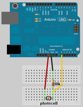
    In this project, I have connected an Arduino to my computer and used a photoresistor to control an animation on the screen. Other sensors could have been used, but I chose a photoresistor because it feels like magic!!

    The photoresistor responds to changes in ambient light as my hand moves up and down. The Arduino sends the reading to a Processing sketch on the computer via a Serial command (through the USB cable). The processing sketch interprets the signal from the Arduino and selects the appropriate picture to display.

    I took a series of screenshots from the following YouTube video: http://www.youtube.com/watch?v=h6nE8m74kDg  And after borrowing a bit of code from these sites (1,2), the project was born.
    This idea is not new, nor my own. There are many people who have done this project before, but I thought to blog about how I have done it, just for fun.

    The Project Movie


    Components Required


    • Arduino Uno (and associated software), and USB cable
    • Photoresistor or Photocell
    • 10K resistor
    • Wires to put it all together
    • Processing IDE from http://processing.org
    • Computer/laptop


    The Arduino Sketch


    The Arduino Code:

    You can download the Arduino IDE from this site.
     1
    2
    3
    4
    5
    6
    7
    8
    9
    10
    11
    12
    13
    14
    15
    16
    17
    18
    19
    20
    21
    22
    23
    24
    25
    26
    27
    28
    29
    30
    31
    32
    33
    34
    35
    36
    37
    38
    39
    40
    41
    42
    43
    44
    45
    46
    47
    48
    49
    /* Jumper: Using an Arduino to animate:
    Written by ScottC on 02/06/2012 */

    int photoRPin = 0;
    int minLight;
    int maxLight;
    int lightLevel;
    int adjustedLightLevel;
    int oldLightLevel;

    void setup() {
    Serial.begin(9600);

    //Setup the starting light level limits
    lightLevel=analogRead(photoRPin);
    minLight=lightLevel-10;
    maxLight=lightLevel;
    oldLightLevel=lightLevel;
    }

    void loop(){
    lightLevel=analogRead(photoRPin);
    delay(10);

    //auto-adjust the minimum and maximum limits in real time
    if(minLight>lightLevel){
    minLight=lightLevel;
    }
    if(maxLight<lightLevel){
    maxLight=lightLevel;
    }

    //Map the light level to produce a result between 1 and 28.
    adjustedLightLevel = map(lightLevel, (minLight+20), (maxLight-20), 1, 28);
    adjustedLightLevel = constrain (adjustedLightLevel, 1,28);

    /*Only send a new value to the Serial Port if the
    adjustedLightLevel value changes.*/
    if(oldLightLevel==adjustedLightLevel){
    //do nothing if the old value and the new value are the same.
    }else{
    //Update the oldLightLevel value for the next round
    oldLightLevel=adjustedLightLevel;

    /*Send the adjusted Light level result
    to Serial port (processing)*/
    Serial.println(adjustedLightLevel);
    }
    }

    The code above was formatted using this site.


    The Processing Code:

    You can download the Processing IDE from this site.

     1
    2
    3
    4
    5
    6
    7
    8
    9
    10
    11
    12
    13
    14
    15
    16
    17
    18
    19
    20
    21
    22
    23
    24
    25
    26
    27
    28
    29
    30
    31
    32
    33
    34
    35
    36
    37
    38
    39
    40
    41
    42
    43
    44
    45
    46
    47
    48
    49
    50
    51
    52
    53
    54
    55
    56
    57
    58
    59
    60
    61
    62
    63
    64
    65
    66
    67
    68
    69
    70
    71
    72
    73
    74
    75
    76
    77
    /* Jumper: Using an Arduino to animate
    Written by ScottC on 02/06/2012

    Source code derived from :
    http://processing.org/learning/topics/sequential.html
    http://processing.org/discourse/beta/num_1267080062.html

    Pictures captured from:
    http://www.youtube.com/watch?v=h6nE8m74kDg

    ======================================================= */

    import processing.serial.*;
    Serial myPort;
    String sensorReading="";

    // Create the array that will hold the images
    PImage[] movieImage = new PImage[29];

    /* The frame variable is used to control which
    image is displayed */
    int frame = 1;


    /* Setup the size of the window. Initialise serial communication with Arduino
    and pre-load the images to be displayed later on. This is done only once.
    I am using COM6 on my computer, you may need replace this value with your
    active COM port being used by the Arduino.*/

    void setup(){
    size(700,600);

    myPort = new Serial(this, "COM6", 9600);
    myPort.bufferUntil('\n');

    for(int i=0;i<28;i++){
    movieImage[i] = loadImage("Jumper" + (i+1) + ".jpg");
    }
    }


    // The draw function controls the animation sequence.

    void draw(){

    //this draws the relevant image to the window
    image(movieImage[frame-1],0,0,width,height);
    }

    void serialEvent (Serial myPort){
    sensorReading = myPort.readStringUntil('\n');
    if(sensorReading != null){
    sensorReading=trim(sensorReading);
    if (sensorReading.length()<2){
    frame = integerFromChar(sensorReading.charAt(0));
    }else{
    frame = integerFromChar(sensorReading.charAt(0))*10;
    frame += integerFromChar(sensorReading.charAt(1));
    }
    }
    }


    /* This function used to convert the character received from the
    serial port (Arduino), and converts it to a number */

    int integerFromChar(char myChar) {
    if (myChar < '0' || myChar > '9') {
    return -1;
    }else{
    return myChar - '0';
    }
    }

    The code above was formatted using this site.


    The pictures 

    Captured from this YouTube Video: http://www.youtube.com/watch?v=h6nE8m74kDg


    Mouse Controlling Arduino LEDs


    Use a mouse to control LEDs attached to an Arduino. This project uses the processing language to transmit the mouse coordinates to the Arduino, which then uses this information to turn on some LEDs. Please see the video below to see it in action.


    Components Required for this project:

    • Arduino UNO
    • Breadboard
    • 9 LEDs
    • 9 x 330 ohm resistors
    • Wires to connect the circuit
    • USB connection cable: to connect the computer to the Arduino
    • A computer: to run the processing sketch, and to compile / upload the Arduino sketch
    • Processing Program installed on computer
    • Arduino Program installed on the computer

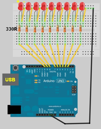
    Arduino Sketch


    This was made using Fritzing.

    Arduino Code

    You can download the Arduino IDE from this site.

     1
    2
    3
    4
    5
    6
    7
    8
    9
    10
    11
    12
    13
    14
    15
    16
    17
    18
    19
    20
    21
    22
    23
    24
    25
    26
    27
    28
    29
    30
    31
    32
    33
    34
    35
    36
    37
    38
    39
    40
    41
    42
    /* This program was created by ScottC on 9/5/2012 to receive serial 
    signals from a computer to turn on/off 1-9 LEDs */

    void setup() {
    // initialize the digital pins as an output.
    pinMode(2, OUTPUT);
    pinMode(3, OUTPUT);
    pinMode(4, OUTPUT);
    pinMode(5, OUTPUT);
    pinMode(6, OUTPUT);
    pinMode(7, OUTPUT);
    pinMode(8, OUTPUT);
    pinMode(9, OUTPUT);
    pinMode(10, OUTPUT);
    // Turn the Serial Protocol ON
    Serial.begin(9600);
    }

    void loop() {
    byte byteRead;

    /* check if data has been sent from the computer: */
    if (Serial.available()) {

    /* read the most recent byte */
    byteRead = Serial.read();
    //You have to subtract '0' from the read Byte to convert from text to a number.
    byteRead=byteRead-'0';

    //Turn off all LEDS
    for(int i=2; i<11; i++){
    digitalWrite(i, LOW);
    }

    if(byteRead>0){
    //Turn on the relevant LEDs
    for(int i=1; i<(byteRead+1); i++){
    digitalWrite(i+1, HIGH);
    }
    }
    }
    }

    The code above was formatted using this site.


    Processing Code

    You can download the Processing IDE from this site.

     1
    2
    3
    4
    5
    6
    7
    8
    9
    10
    11
    12
    13
    14
    15
    16
    17
    18
    19
    20
    21
    22
    23
    24
    25
    26
    27
    28
    29
    30
    31
    32
    33
    34
    35
    36
    37
    38
    39
    40
    41
    42
    43
    44
    45
    46
    47
    48
    49
    50
    51
    52
    53
    54
    //Created by ScottC on 12/05/2012 to send mouse coordinates to Arduino

    import processing.serial.*;

    // Global variables
    int new_sX, old_sX;
    int nX, nY;
    Serial myPort;

    // Setup the Processing Canvas
    void setup(){
    size( 800, 400 );
    strokeWeight( 10 );

    //Open the serial port for communication with the Arduino
    //Make sure the COM port is correct
    myPort = new Serial(this, "COM6", 9600);
    myPort.bufferUntil('\n');
    }

    // Draw the Window on the computer screen
    void draw(){

    // Fill canvas grey
    background( 100 );

    // Set the stroke colour to white
    stroke(255);

    // Draw a circle at the mouse location
    ellipse( nX, nY, 10, 10 );

    //Draw Line from the top of the page to the bottom of the page
    //in line with the mouse.
    line(nX,0,nX,height);
    }


    // Get the new mouse location and send it to the arduino
    void mouseMoved(){
    nX = mouseX;
    nY = mouseY;

    //map the mouse x coordinates to the LEDs on the Arduino.
    new_sX=(int)map(nX,0,800,0,10);

    if(new_sX==old_sX){
    //do nothing
    } else {
    //only send values to the Arduino when the new X coordinates are different.
    old_sX = new_sX;
    myPort.write(""+new_sX);
    }
    }

    The code above was formatted using this site.

    Reading from a Text File and Sending to Arduino

    The following tutorial will demonstrate how to Read values from a Text file (.txt, .csv) to blink 1 of 9 LEDs attached to an Arduino. It uses the combination of an Arduino and Processing program to process the file. The Processing program will read the text file in real time, only sending new information to the Arduino.


    Components Required

    • Arduino UNO
    • Breadboard
    • 9 LEDs
    • 9 x 330 ohm resistors
    • Wires to connect the circuit
    • USB connection cable: to connect the computer to the Arduino
    • A computer: to run the processing sketch, and to compile / upload the Arduino sketch
    • Processing Program installed on computer
    • Arduino Program installed on the computer
    • A comma separated text file (*.txt).


    Arduino Layout


    The Text File

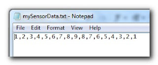
    • Open Notepad or equivalent text file editor, and paste the following data into it.

    1,2,3,4,5,6,7,8,9,8,7,6,5,4,3,2,1

    • Save the file on your hard drive. In my case, I have chosen to save the file at this location.

    D:/mySensorData.txt

    • It should look like the following screenshot


    Additional notes regarding the Text file:
    • Just remember what you call it, and where you saved it, because we will be referring to this file later on in the Processing script.
    • Keep all values on the same line.
    • Separate each number with a comma.
    • The number 1 will blink the first LED which is attached to Pin 2 on the Arduino.
    • The number 9 will blink the last LED which is attached to Pin 10 on the Arduino.


    Processing Code

    You can download the Processing IDE from this site.

     1
    2
    3
    4
    5
    6
    7
    8
    9
    10
    11
    12
    13
    14
    15
    16
    17
    18
    19
    20
    21
    22
    23
    24
    25
    26
    27
    28
    29
    30
    31
    32
    33
    34
    35
    36
    37
    38
    39
    40
    41
    42
    43
    44
    45
    46
    47
    48
    49
    50
    51
    52
    53
    54
    55
    56
    57
    58
    59
    60
    61
    62
    63
    64
    65
    66
    67
    68
    69
    70
    71
    72
    73
    74
    75
    76
    77
    78
    79

    style="color: blue;">import
    processing.serial.*;

    style="color: blue;">import
    java.io.*;

    style="color: rgb(43, 145, 175);">int
    mySwitch=0;

    style="color: rgb(43, 145, 175);">int
    counter=0;
    String [] subtext;
    Serial myPort;


    style="color: rgb(43, 145, 175);">void
    setup(){

    style="color: green;">//Create a switch that will control the frequency of text file reads.


    style="color: green;">//When mySwitch=1, the program is setup to read the text file.


    style="color: green;">//This is turned off when mySwitch = 0

    mySwitch=1;


    style="color: green;">//Open the serial port for communication with the Arduino


    style="color: green;">//Make sure the COM port is correct

    myPort =
    style="color: blue;">new
    Serial(this,
    style="color: rgb(163, 21, 21);">"COM6"
    , 9600);
    myPort.bufferUntil(
    style="color: rgb(163, 21, 21);">'\n'
    );
    }


    style="color: rgb(43, 145, 175);">void
    draw() {

    style="color: blue;">if
    (mySwitch>0){

    style="color: green;">/*The readData function can be found later in the code.


    style="color: green;"> This is the call to read a CSV file on the computer hard-drive. */

    readData(
    style="color: rgb(163, 21, 21);">"D:/mySensorData.txt"
    );


    style="color: green;">/*The following switch prevents continuous reading of the text file, until


    style="color: green;"> we are ready to read the file again. */

    mySwitch=0;
    }

    style="color: green;">/*Only send new data. This IF statement will allow new data to be sent to


    style="color: green;"> the arduino. */


    style="color: blue;">if
    (counter<subtext.length){

    style="color: green;">/* Write the next number to the Serial port and send it to the Arduino


    style="color: green;"> There will be a delay of half a second before the command is


    style="color: green;"> sent to turn the LED off : myPort.write('0'); */

    myPort.write(subtext[counter]);
    delay(500);
    myPort.write(
    style="color: rgb(163, 21, 21);">'0'
    );
    delay(100);

    style="color: green;">//Increment the counter so that the next number is sent to the arduino.

    counter++;
    }
    style="color: blue;">else
    {
    //If the text file has run out of numbers, then read the text file again in 5 seconds.
    delay(5000);
    mySwitch=1;
    }
    }


    style="color: green;">/* The following function will read from a CSV or TXT file */


    style="color: rgb(43, 145, 175);">void
    readData(String myFileName){

    File file=
    style="color: blue;">new
    File(myFileName);
    BufferedReader br=
    style="color: blue;">null
    ;

    try{
    br=
    style="color: blue;">new
    BufferedReader(
    style="color: blue;">new
    FileReader(file));
    String text=
    style="color: blue;">null
    ;


    style="color: green;">/* keep reading each line until you get to the end of the file */


    style="color: blue;">while
    ((text=br.readLine())!=
    style="color: blue;">null
    ){
    /* Spilt each line up into bits and pieces using a comma as a separator */
    subtext = splitTokens(text,
    style="color: rgb(163, 21, 21);">","
    );
    }
    }
    style="color: blue;">catch
    (FileNotFoundException e){
    e.printStackTrace();
    }
    style="color: blue;">catch
    (IOException e){
    e.printStackTrace();
    }
    style="color: blue;">finally
    {
    try {

    style="color: blue;">if
    (br != null){
    br.close();
    }
    }
    style="color: blue;">catch
    (IOException e) {
    e.printStackTrace();
    }
    }
    }

    I used this site to highlight and format my code.

    Once you have copied the text above into the Processing IDE, you can now start working on the Arduino code as seen below.


    Arduino Code

    You can download the Arduino IDE from this site.

    Copy and paste the following code into the Arduino IDE.

     1
    2
    3
    4
    5
    6
    7
    8
    9
    10
    11
    12
    13
    14
    15
    16
    17
    18
    19
    20
    21
    22
    23
    24
    25
    26
    27
    28
    29
    30
    31
    32
    33
    34
    35
    36
    37
    38
    39
    40
    41
    42
    43
    44
    45
    46
    47
    48
    49

    style="color: green;">/* This program was created by ScottC on 8/5/2012 to receive serial


    style="color: green;">signals from a computer to turn on/off 1-9 LEDs */


    style="color: rgb(43, 145, 175);">void
    setup() {

    style="color: green;">// initialize the digital pins as an output.

    pinMode(2, OUTPUT);
    pinMode(3, OUTPUT);
    pinMode(4, OUTPUT);
    pinMode(5, OUTPUT);
    pinMode(6, OUTPUT);
    pinMode(7, OUTPUT);
    pinMode(8, OUTPUT);
    pinMode(9, OUTPUT);
    pinMode(10, OUTPUT);

    style="color: green;">// Turn the Serial Protocol ON

    Serial.begin(9600);
    }


    style="color: rgb(43, 145, 175);">void
    loop() {

    style="color: rgb(43, 145, 175);">byte
    byteRead;


    style="color: green;">/* check if data has been sent from the computer: */


    style="color: blue;">if
    (Serial.available()) {


    style="color: green;">/* read the most recent byte */

    byteRead = Serial.read();

    style="color: green;">//You have to subtract '0' from the read Byte to convert from text to a number.

    byteRead=byteRead-
    style="color: rgb(163, 21, 21);">'0'
    ;


    style="color: green;">//Turn off all LEDs if the byte Read = 0


    style="color: blue;">if
    (byteRead==0){

    style="color: green;">//Turn off all LEDS

    digitalWrite(2, LOW);
    digitalWrite(3, LOW);
    digitalWrite(4, LOW);
    digitalWrite(5, LOW);
    digitalWrite(6, LOW);
    digitalWrite(7, LOW);
    digitalWrite(8, LOW);
    digitalWrite(9, LOW);
    digitalWrite(10, LOW);
    }


    style="color: green;">//Turn LED ON depending on the byte Read.


    style="color: blue;">if
    (byteRead>0){
    digitalWrite((byteRead+1), HIGH);
    style="color: green;">// set the LED on

    }
    }
    }

    Additional Information:
    • The Arduino code will still work without the processing program. You can open the serial monitor window to send the commands to the Arduino manually. In fact, if you encounter any problems, I would suggest you do this. It will help to identify the root cause of the problem (ie Processing or Arduino Code, or physical connections).
    • If you choose to use the Serial Monitor feature of the Arduino IDE, you cannot use the Processing program at the same time.

    Once you have assembled the Arduino with all the wires, LEDs, resistors etc, you should now be ready to put it all together and get this baby cranking!


    Connecting it all together

    • Connect the USB cable from your computer to the Arduino, and upload the code.
    • Keep the USB cable connected between the Arduino and the computer, as this will become the physical connection needed by the Processing Program
    • Make sure that you have the text file in the correct location on your hard drive, and that it only contains numbers relevant to the code provided (separated by commas).
    • Run the Processing program and watch the LEDs blink in the sequence described by the text file.
    • You can add more numbers to the end of the line, however, the processing program will not be aware of them until you save the file. The text file does not have to be closed.
    Other programs can be used to create text file, but you will need the processing program to read the file and send the values to the Arduino. The Arduino will receive each value and react appropriately.

    SIMILAR PROJECT: Use a mouse to control the LEDs on your Arduino - see this post.


    An alternative Processing Sketch

    This Processing sketch uses the loadStrings()method instead of the FileReader method used in the first sketch. This sketch also provides better control over sending the values to the Arduino. When the sketch first loads, the application window will be red. By clicking your mouse inside the window, the background will turn green and the file will be imported and sent to the Arduino, with every value being sent at half second intervals. If you update the text file and save, only new values will be transmitted, however, if you want the entire file to transmit again, you can press the window once (to reset the counter), and then again to read the file and send the values again from the beginning of the file.
    I personally like this updated version better than the first, plus I was inspired to update this blog posting due to the fact that some people were having problems with the FileReader method in the first sketch. But both sketches should work (they worked for me).


     1
    2
    3
    4
    5
    6
    7
    8
    9
    10
    11
    12
    13
    14
    15
    16
    17
    18
    19
    20
    21
    22
    23
    24
    25
    26
    27
    28
    29
    30
    31
    32
    33
    34
    35
    36
    37
    38
    39
    40
    41
    42
    43
    44
    45
    46
    47
    48
    49
    50
    51
    52
    53
    54
    55
    56
    57
    58
    59
    60
    61
    62

    style="color: rgb(0, 128, 0);">/* TextFile Sender: Written by Scott C on 5th April 2013


    style="color: rgb(0, 128, 0);"> using Processing Version 2.0b8 */


    import processing.serial.*;

    Serial comPort;

    style="color: rgb(43, 145, 175);">int
    counter=0;
    style="color: rgb(0, 128, 0);">// Helps to keep track of values sent.


    style="color: rgb(43, 145, 175);">int
    numItems=0;
    style="color: rgb(0, 128, 0);">//Keep track of the number of values in text file

    boolean sendStrings=
    style="color: rgb(0, 0, 255);">false
    ;
    style="color: rgb(0, 128, 0);">//Turns sending on and off

    StringLoader sLoader;
    style="color: rgb(0, 128, 0);">//Used to send values to Arduino


    style="color: rgb(43, 145, 175);">void
    setup(){
    comPort =
    style="color: rgb(0, 0, 255);">new
    Serial(
    style="color: rgb(0, 0, 255);">this
    , Serial.list()[0], 9600);
    background(255,0,0);
    style="color: rgb(0, 128, 0);">//Start with a Red background

    }


    style="color: rgb(43, 145, 175);">void
    draw(){
    }


    style="color: rgb(43, 145, 175);">void
    mousePressed() {

    style="color: rgb(0, 128, 0);">//Toggle between sending values and not sending values

    sendStrings=!sendStrings;


    style="color: rgb(0, 128, 0);">//If sendStrings is True - then send values to Arduino


    style="color: rgb(0, 0, 255);">if
    (sendStrings){
    background(0,255,0);
    style="color: rgb(0, 128, 0);">//Change the background to green


    style="color: rgb(0, 128, 0);">/*When the background is green, transmit


    style="color: rgb(0, 128, 0);"> text file values to the Arduino */

    sLoader=
    style="color: rgb(0, 0, 255);">new
    StringLoader();
    sLoader.start();
    }
    style="color: rgb(0, 0, 255);">else
    {
    background(255,0,0);
    style="color: rgb(0, 128, 0);">//Change background to red


    style="color: rgb(0, 128, 0);">//Reset the counter

    counter=0;
    }
    }


    style="color: rgb(0, 128, 0);">/*============================================================*/


    style="color: rgb(0, 128, 0);">/* The StringLoader class imports data from a text file


    style="color: rgb(0, 128, 0);"> on a new Thread and sends each value once every half second */


    style="color: rgb(0, 0, 255);">public

    style="color: rgb(0, 0, 255);">class

    style="color: rgb(43, 145, 175);">StringLoader
    extends Thread{


    style="color: rgb(0, 0, 255);">public
    StringLoader(){

    style="color: rgb(0, 128, 0);">//default constructor

    }


    style="color: rgb(0, 0, 255);">public

    style="color: rgb(43, 145, 175);">void
    run() {
    String textFileLines[]=loadStrings(
    style="color: rgb(163, 21, 21);">"d:/mySensorData.txt"
    );
    String lineItems[]=splitTokens(textFileLines[0],
    style="color: rgb(163, 21, 21);">","
    );
    numItems=lineItems.length;

    style="color: rgb(0, 0, 255);">for
    (
    style="color: rgb(43, 145, 175);">int
    i = counter; i<numItems; i++){
    comPort.write(lineItems[i]);
    delay(500);
    comPort.write(
    style="color: rgb(163, 21, 21);">"0"
    );
    }
    counter=numItems;
    }
    }


    ScottC 09 May 14:09

    Speech / Voice Recognition. Arduino project, next in a series FFT and Arduino.

     Finally, I’d like to present  the most sophisticated project I’ve done so far, build around the idea turning Arduino board into a DSP.  The results are really impressive for small microprocessor, with low memory size and low MIPS. IMHO, arduino provides better results, than Windows Vista VR system, with 1 GB / 2.2 GHz  hardware, for short one-two words commands, of course.
    No HMM, neural networks, or other very popular and “scientifically sounding” theories, were considered to be implemented in the algorithm. Google brings up  millions links on a topic, just ask, but only few of them are designed on really scientific concept, rather than dumb data base “sharpening”. I’m not saying they are completely wrong, and I’m not an expert in the field, but they are not smart ether. My decision is simple 2D cross-correlation. Basically, the heart of the recognition algorithm is similar to an image matching program, which works the same way for voice/sound.  To create a Spectrogram image, arduino is continuously monitoring sound level via microphone, and start capturing data when VOX threshold is exceeded. After input array “X” filled up, data transfered on next level to calculate FFT. The same “conveyor belt” works between FFT and Filtering, flags raised when data is ready, and flags lowered when process finished. The only difference is a speed, conveyor belt is running faster passing data ADC-FFT, and slower at Filter-Correlation stage, as it requires 64 regular cycles to complete spectrogram image in one SuperCycle.  The most time consuming part is Edge Enhancement / HPF Filtering of the spectrogram. I’m still looking around to improve performance of this stage, as it holds all process back from to be fully “Real Time”.
     Specification:
    -  4 kHz sampling rate:  2 kHz voice freq. range;
    -  64 FFT subroutine,    62.5 Hz spectral resolution;
    -  16 x 64 Spectrogram Image, around 1 second max voice password;
    -  duration of the Cross-Correlation < 5 milliseconds;
    -  duration of the FFT+SQRT+Compression < 4 milliseconds;
    -  duration of the Edge Enhancement ~ 35 milliseconds;Main cycle time frame is 16 milliseconds, it’s defined by sampling rate x FFT size, 0.25 x 64 = 64 millisecond. Super-cycle 1.024 is needed only because EE prevents all processes to be completed in less than 16 milliseconds. There is a resources left, to increase sampling up to 8 or even 12 kHz, I just had no time to conduct experiments if it is beneficial.

    There is a Command Line Interface, built-in the software, which control “record” and debug “print” functions, 7 commands for now:
    if (incomingByte == ‘x’) {           // INPUT ADC DATA
    if (incomingByte == ‘f’) {           // FFT OUTPUT
    if (incomingByte == ‘s’) {           // SPECROGRAMM PRE  FILTERED
    if (incomingByte == ‘g’) {           // SPECROGRAMM POST FILTERED
    if (incomingByte == ‘r’) {           // RECORD SPECROGRAMM TO EEPROM
    if (incomingByte == ‘p’) {           // PLAY SPECROGRAMM FROM EEPROM
    if (incomingByte == ‘m’) {           // FREE MEMORY BYTES

    Software is written for AtMega328p microprocessor, Arduino Uno board or similar. For others, all referenced registers has to be replaced with appropriate names for microprocessor.Compiles on 022 IDE, there are some conflicts with 1.0 IDE, that I was not feel myself right to troubleshoot yet. For better understanding some math background, have a look at my previous posts.

    Link to download a sketch:   Voice_Recognition_24_01

    Analog front-end is the same, as I used in my first project: Color Ogran
    There is not much could be improved on this part, and I again used both inputs – from microphone to do tests with my own voice, and also from “line” input, for single tone test generated by computer during debugging. Next picture shows “s” command print-out in the serial monitor window, after I pronounce a word : “Spectrogram” . Due limited size of the window, data printed with 90 degree rotation, left-right is frequencies bands direction, and up-down is time. Lower freq. on left side (60 Hz) and higher (2 kHz) on the right.  The same time 3D images generated in right view angle.

    This is how spectrogram looks like after “g” command entered in serial monitor and word sounds just right after that:

    Next couple images created with single tone frequency  (320 Hz), just to show more clear “internal properties” of the filtering, again “s” and “g” commands were entered:

    Well, as tone sounds continuously, it shows filtering in one direction only, and not the best tutorial on edge-enhancement theory. (“Home brew” lab limits). The same time last picture shows, that each “peek” on the original spectrogram, become surrounded by negative smaller peeks, resulting in “0″ overall sum  on 3×3 foot-print, and consequently on the whole map. In electronics it goes under HPF name, and essence of process is to remove DC component, plus attenuate  Low Frequencies.
    Excelent on-line book

    Short manual:
    to be completed later


    Optical Magnet, Arduino project next in a series Laser Tracking 3D

    This blog considered to be next stage in the series published earlier, concentrated around the idea tracking object in the space. There are an enormous quantity of similar projects could be developed on this platform. I’ll name a few:

    - star / rocket / vehicle tracking;
    - follow me / robot / hands / cap etc;
    - navigation to charging station / landing pad / around area;
    - contact-less measurements rotational speed / angle to surface / shifting.

    All of this on a few dollars micro-controller and cheap CMOS camera! Real-time, up to 60 Hz update rate!
    Please, check on the first and second version, as I’d skip explanation basic design concept here.

      Most important features in this series of projects:

    * 1. LOCALIZATION XY.
    * 2. RANGE FINDER Z.
    * 3. TRACKING 3-D.
    * 4. TRACE TOOL.
    * 5. TRACKING 6-D.
    * 6. OPTICAL MAGNET.

    Feature considered to be independent, so you can star  from  project 1:
    http://fftarduino.blogspot.com/2011/12/arduino-laser-3d-tracking-range-finder.html
    than move on next stage, and so on depends on a budget, parts availability or your interest!

    This version of hardware/software system design capable to track object in

    6 – D ++ space:

    *   -  Linear motion along X, Y, Z coordinates (3D);
    *   -  Rotation around fixed axis (6D);

    I put two ++ plus signs, in order to underline capability of the hardware design to track Rotation of the object based not only on distance measurements, but also Reflectivity. As Power Control Loop strictly hold lasers radiation under control, simple calculation in periodicity of the emitted power would provide information about angular speed round / cylindrical object. Phase difference in 4 signals gives rotational center for Z. It’s also apply for linear motion, tracking of the object could be based on reflectivity or distance or BOTH simultaneously ,  which opens enormously great amount of possibilities.

    Optical Magnet:
    *  – Attract closest surface;
    *  – Repel;
    *  – Attract or repel surface with specific reflectivity (BLACK, WHITE, OR COLOR)!!!
    *    * work in progress, Reflectivity math are not implemented yet       *
    *    * algorithm to track rotation is not included, this is version for demonstration purposes  mainly.*

    Link to download Arduino Uno sketch:  Optical_Magnet_6D

    8 January, 2012.
    Release notes of the version 3.2 software:

    -  Video is De-interlaced, full image size 512 (active 492) lines;
    -  digitalWrite, analogWrite functions of the arduino IDE were replaced by direct port manipulation, in order  to improve time performance of critical section of the code – interrupt subroutine and to avoid blocking interruption call (functions have locking mechanism in theirs body);
    - minor changes in Power Control Loop algorithm, to prevent oscillation;

    Link to download Arduino Uno sketch:  Optical_Magnet_6D_V3

     finished…