Posts with «projects» label

Project Review – Silicon Chip Capacitance Substitution Box

Introduction

Every month Australian electronics magazine Silicon Chip publishes a variety of projects, and in some cases various (well … one of two) electronics retailers will pick up the project and offer it as a kit. However for an increasing number of new projects they don’t, which leaves the interested reader with one option – build the entire project from scratch.

But thankfully this is no longer the case – as the team from Silicon Chip now offer a range of project PCBs and matching front panels for sale directly from their website. Although buying these parts is not the cheapest option, it gives the busy person who likes making things a quick start – or the inexperienced more opportunities to complete a successful project.

So as a test of this new service, I bought the PCB and front panel for the Capacitance Substitution Box project described by Nicholas Vinen in the Juily 2012 issue of SC:

This is something I’ve meant to make for a while – but didn’t really have the inclination to make one from scratch, so it was neat to see a version published in the magazine. I believe the subjects in the magazine article are oftern prototypes, which explains the difference in colour for the front panel.

The parts arrived in a week after placing the order, and are of a high quality:

When complete, the capacitance substitution box PCB and panel will fit nicely into an Altronics H0151 enclosure, so you don’t need to do any drilling or filing. The next task was to organise the required parts. The rotary switches, terminal posts and the usual odds and ends can be found at Altronics, Jaycar or other suppliers. However the main components – the capacitors – offered two options.

The first option is to simply use capacitors from personal stock or the stores. However the tolerance of these parts can vary wildly, with up to twenty percent either way. This is ok for simple uses, however when values are combined – the tolerance of larger values can negate the lower values completely. So instead I’ve chosen the second option – which involves using brand-name low-tolerance capacitors.

Thus I turned to element14 who stock not only a huge range of not only regular but also the low-tolerance capacitors, and can also have them on my desk usually by the next working day. Finally, it’s nice to have all the parts arrive in little bags… neatly organised ready to go:

It’s easy to search for low-tolerance parts with element14, as the automatic filtering has tolerance as a parameter:

Furthermore you can also ensure you have the voltage rating of at least 50V DC as well. So after half an hour the capacitor order was completed and arrived when expected – using parts from Panasonic, Vishay, and Wima. The tolerances of our capacitors used varied between one and ten percent, which will help improve the accuracy of the substitution box.

Assembly

The PCB has the capacitor values labelled neatly on the silk-screen, so soldering in all the capacitors was a relatively simple but long operation. Having them arrive in separate packets made life a lot easier. During the soldering process it’s a good idea to have a  break or two, which helps you avoid fatigue and making any mistakes.

There may be a few capacitors that are a little too wide to fit with the others, so they can be mounted on the other side of the PCB:

However they all end up fitting well:

The next step was to configure the first rotary switch for six position use, then cut the plastic stopped from the side of each rotary switch. In the following image you have a before and after example:

Now the rotary switches can have their shafts trimmed and then be soldered onto the PCB:

However ensure you have the first rotary switch in the right way – that is the selections are selected across the top half, not the bottom. Remove the nuts from the rotary switches, and double-check all the capacitors are fitted, as once the next step is completed … going back will be difficult to say the least.

At this point the banana sockets can be fitted to the panel, and then soldered into place, and then you’re finished. Just place the panel/PCB combination inside the box and screw it down:

Using the Capacitance Substitution Box

Does it work? Yes – however you don’t get exact values, there will always be a tolerance due to the original tolerance of the capacitors used and the stray capacitance of the wires between the box and the circuit (or capacitance meter). Nevertheless our example was quite successful. You can see the box in action with our Altronics LC meter kit in this video.

Again, using the best tolerance capacitors you can afford will increase the accuracy of this project.

Conclusion

Over time this would be a useful piece of equipment to have – so if your experiments or projects require varying capacitor value, this project will serve the purpose nicely. Plus it helps with mental arithmetic and measures of capacitance! Please do not ask me for copies of the entire Silicon Chip article, refusal may offend. Instead – visit their website for a reprint or digital access.

And if you enjoyed this article, or want to introduce someone else to the interesting world of Arduino – check out my book (now in a third printing!) “Arduino Workshop”.

Have fun and keep checking into tronixstuff.com. Why not follow things on twitterGoogle+, subscribe  for email updates or RSS using the links on the right-hand column, or join our forum – dedicated to the projects and related items on this website. Sign up – it’s free, helpful to each other –  and we can all learn something.

The post Project Review – Silicon Chip Capacitance Substitution Box appeared first on tronixstuff.

Project – Arduino “Book Monster”

Introduction

Recently we saw a neat project by the people from Evil Mad Scientist – their “Peek-O-Book“, a neat take on a book with a shy monster inside, based on hardware from their Snap-O-Lantern kit. Not wanting to fork out for the postage to Australia we decided to make our own version, of which you can follow along.

This is a fun project that doesn’t require too much effort and has a lot of scope for customisation. There’s no right or wrong when making your own (or this one!) so just have fun with it.

Construction

First, you’ll need a book of some sort, something large enough to hide the electronics yet not too large to look “suspicious” – then cut the guts out to make enough space for the electronics. Then again it’s subjective, so get whatever works for you. Coincidentally we found some “dummy books” (not books for dummies) that were perfect for the job:

After spraying the inside with matt black paint, the inside is better suited for the “eyes in the dark” effect required for the project:

The “book” had a magnet and matching metal disk on the flap to aid with keep the cover shut, however this was removed as it will not allow for smooth opening with the servo.

The electronics are quite simple if you have some Arduino or other development board experience. Not sure about Arduino? You can use any microcontroller that can control a servo and some LEDs. We’re using a Freetronics LeoStick as it’s really small yet offers a full Arduino Leonardo-compatible experience, and a matching Protostick to run the wires and power from:

By fitting all the external wiring to the Protostick you can still use the main LeoStick for other projects if required. The power is from 4 x AA cells, with the voltage reduced with a 1n4004 diode:

And for the “eyes” of our monster – you can always add more if it isn’t too crowded in the book:

We’ll need a resistor as well for the LEDs. As LEDs are current driven you can connect two in series with a suitable dropping resistor which allows you to control both if required with one digital output pin. You can use the calculator here to help determine the right value for the resistor.

Finally a servo is required to push the lid of the book up and down. We used an inexpensive micro servo that’s available from Tronixlabs:

The chopsticks are cut down and used as an extension to the servo horn to give it more length:

Don’t forget to paint the arm black so it doesn’t stand out when in use. We had a lazy attack and mounted the servo on some LEGO bricks held in with super glue, but it works. Finally, here is the circuit schematic for our final example – we also added a power switch after the battery pack:

To recap  – this is a list of parts used:

After some delicate soldering the whole lot fits neatly in the box:

Arduino Sketch

The behaviour of your “book monster” comes down to your imagination. Experiment with the servo angles and speed to simulate the lid opening as if the monster is creeping up, or quickly for a “pop-up” surprise. And again with the LED eyes you can blink them and alter the brightness with PWM. Here’s a quick sketch to give you an idea:

int angle;
int d; // for delays
int ledPin = 9; // LEDs on digital pin 9

#include <Servo.h>
Servo myservo;

void setup()
{
  myservo.attach(4); // servo control pin on digital 4
  pinMode(9, OUTPUT); 
  randomSeed(analogRead(0));
  myservo.write(10);
  delay(5000);
}

void behaviour1()
{
  for (angle = 10; angle <=40; angle++)
  {
    myservo.write(angle);
    delay(50);
  }
  digitalWrite(ledPin, HIGH);
  delay(250);
  digitalWrite(ledPin, LOW);
  delay(250);  
  digitalWrite(ledPin, HIGH);
  delay(250);
  digitalWrite(ledPin, LOW);
  delay(250);    
  digitalWrite(ledPin, HIGH);
  delay(1000);
  digitalWrite(ledPin, LOW);
  delay(250);    
  digitalWrite(ledPin, HIGH);
  delay(1000);
  digitalWrite(ledPin, LOW);
  delay(250);    
  digitalWrite(ledPin, HIGH);
  delay(1000);
  digitalWrite(ledPin, LOW);
  delay(250);    
  for (angle = 40; angle >=10; --angle)
  {
    myservo.write(angle);
    delay(5);
  }
}

void loop()
{
  behaviour1();
  delay(random(60000));
}

You can watch our example unit in this video.

Frankly the entire project is subjective, so just do what you want.

Conclusion

Well that was fun, and I am sure this will entertain many people. A relative is a librarian so this will adorn a shelf and hopefully give the children a laugh. Once again, thanks to the people from Evil Mad Science for the inspiration for this project – so go and buy something from their interesting range of kits and so on.

And if you enjoyed this article, or want to introduce someone else to the interesting world of Arduino – check out my book (now in a third printing!) “Arduino Workshop”.

Have fun and keep checking into tronixstuff.com. Why not follow things on twitterGoogle+, subscribe  for email updates or RSS using the links on the right-hand column, or join our forum – dedicated to the projects and related items on this website. Sign up – it’s free, helpful to each other –  and we can all learn something.

The post Project – Arduino “Book Monster” appeared first on tronixstuff.

Project – LED Cube Spectrum Analyzer

Introduction

A few weeks ago I was asked about creating a musical-effect display with an RGB LED cube kit from Freetronics, and with a little work this was certainly possible using the MSGEQ7 spectrum analyser IC. In this project we’ll create a small add-on PCB containing the spectrum analyser circuit and show how it can drive the RGB LED cube kit.

Assumed knowledge

To save repeating myself, please familiarise yourself with the MSGEQ7 spectrum aanalyserIC in Chapter 48 of our Arduino tutorials. And learn more about the LED cube from our review and the product page.

You can get MSGEQ7 ICs from various sources, however they had varying results. We now recommend using the neat module from Tronixlabs.

The circuit

The LED cube already has an Arduino Leonardo-compatible built in to the main PCB, so all you need to do is build a small circuit that contains the spectrum analyzer which connects to the I/O pins on the cube PCB and also has audio input and output connections. First, consider the schematic:

For the purposes of this project our spectrum analyser will only display the results from one channel of audio – if you want stereo, you’ll need two! And note that the strobe, reset and DCOUT pins on the MSGEQ7 are labelled with the connections to the cube PCB. Furthermore the pinouts for the MSGEQ7 don’t match the physical reality – here are the pinouts from the MSGEQ7 data sheet (.pdf):

The circuit itself will be quite small and fit on a small amount of stripboard or veroboard. There is plenty of room underneath the cube to fit the circuit if so desired:

With a few moments you should be able to trace out your circuit to match the board type you have, remember to double-check before soldering. You will also need to connect the audio in point after the 1000 pF capacitor to a source of audio, and also pass it through so you can connect powered speakers, headphones, etc.

One method of doing so would be to cut up a male-female audio extension lead, and connect the shield to the GND of the circuit, and the signal line to the audio input on the circuit. Or if you have the parts handy and some shielded cable, just make your own input and output leads:

Be sure to test for shorts between the signal and shield before soldering to the circuit board. When finished, you should have something neat that you can hide under the cube or elsewhere:

Double-check your soldering for shorts and your board plan, then fit to the cube along with the audio source and speakers (etc).

Arduino Sketch

The sketch has two main functions – the first is to capture the levels from the MSGEQ7 and put the values for each frequency band into an array, and the second function is to turn on LEDs that represent the level for each band. If you’ve been paying attention you may be wondering how we can represent seven frequency bands with a 4x4x4 LED cube. Simple – by rotating the cube 45 degrees you can see seven vertical columns of LEDs:

So when looking from the angle as shown above, you have seven vertical columns, each with four levels of LEDs. Thus the strength of each frequency can be broken down into four levels, and then the appropriate LEDs turned on.

After this is done for each band, all the LEDs are turned off and the process repeats. For the sake of simplicity I’ve used the cube’s Arduino library to activate the LEDs, which also makes the sketch easier to fathom. The first example sketch only uses one colour:

// Freetronics CUBE4: and MSGEQ7 spectrum analyser
// MSGEQ7 strobe on A4, reset on D5, signal into A0

#include "SPI.h"
#include "Cube.h"
Cube cube;

int res = 5; // reset pins on D5
int left[7]; // store band values in these arrays
int band;

void setup()
{
  pinMode(res, OUTPUT); // reset
  pinMode(A4, OUTPUT); // strobe
  digitalWrite(res,LOW); 
  digitalWrite(A4,HIGH); 
  cube.begin(-1, 115200);
  Serial.begin(9600);
}

void readMSGEQ7()
// Function to read 7 band equalizers
{
  digitalWrite(res, HIGH);
  digitalWrite(res, LOW);
  for(band=0; band <7; band++)
  {
    digitalWrite(A4,LOW); // strobe pin on the shield - kicks the IC up to the next band 
    delayMicroseconds(30); // 
    left[band] = analogRead(0); // store band reading
    digitalWrite(A4,HIGH); 
  }
}

void loop()
{
  readMSGEQ7();

  for (band = 0; band < 7; band++)
  {
    // div each band strength into four layers, each band then one of the odd diagonals 

    // band one ~ 63 Hz
    if (left[0]>=768) { 
      cube.set(3,3,3, BLUE); 
    } 
    else       
      if (left[0]>=512) { 
      cube.set(3,3,2, BLUE); 
    } 
    else   
      if (left[0]>=256) { 
      cube.set(3,3,1, BLUE); 
    } 
    else       
      if (left[0]>=0) { 
      cube.set(3,3,0, BLUE); 
    } 

    // band two ~ 160 Hz
    if (left[1]>=768) 
    { 
      cube.set(3,2,3, BLUE); 
      cube.set(2,3,3, BLUE);      
    }  
    else
      if (left[1]>=512) 
      { 
        cube.set(3,2,2, BLUE); 
        cube.set(2,3,2, BLUE);      
      } 
      else   
        if (left[1]>=256) 
      { 
        cube.set(3,2,1, BLUE); 
        cube.set(2,3,1, BLUE);      
      } 
      else   
        if (left[1]>=0) 
      { 
        cube.set(3,2,0, BLUE); 
        cube.set(2,3,0, BLUE);      
      } 

    // band three ~ 400 Hz
    if (left[2]>=768) 
    { 
      cube.set(3,1,3, BLUE); 
      cube.set(2,2,3, BLUE);      
      cube.set(1,3,3, BLUE);            
    }  
    else
      if (left[2]>=512) 
      { 
        cube.set(3,1,2, BLUE); 
        cube.set(2,2,2, BLUE);      
        cube.set(1,3,2, BLUE);            
      } 
      else   
        if (left[2]>=256) 
      { 
        cube.set(3,1,1, BLUE); 
        cube.set(2,2,1, BLUE);      
        cube.set(1,3,1, BLUE);            
      } 
      else   
        if (left[2]>=0) 
      { 
        cube.set(3,1,0, BLUE); 
        cube.set(2,2,0, BLUE);      
        cube.set(1,3,0, BLUE);            
      } 

    // band four ~ 1 kHz
    if (left[3]>=768) 
    { 
      cube.set(3,0,3, BLUE); 
      cube.set(2,1,3, BLUE);      
      cube.set(1,2,3, BLUE);            
      cube.set(0,3,3, BLUE);                  
    }  
    else
      if (left[3]>=512) 
      { 
        cube.set(3,0,2, BLUE); 
        cube.set(2,1,2, BLUE);      
        cube.set(1,2,2, BLUE);            
        cube.set(0,3,2, BLUE);                        
      } 
      else   
        if (left[3]>=256) 
      { 
        cube.set(3,0,1, BLUE); 
        cube.set(2,1,1, BLUE);      
        cube.set(1,2,1, BLUE);      
        cube.set(0,3,1, BLUE);                        
      } 
      else   
        if (left[3]>=0) 
      { 
        cube.set(3,0,0, BLUE); 
        cube.set(2,1,0, BLUE);      
        cube.set(1,2,0, BLUE);            
        cube.set(0,3,0, BLUE);                        
      } 

    // band five  ~ 2.5 kHz
    if (left[4]>=768) 
    { 
      cube.set(2,0,3, BLUE); 
      cube.set(1,1,3, BLUE);      
      cube.set(0,2,3, BLUE);            
    }  
    else
      if (left[4]>=512) 
      { 
        cube.set(2,0,2, BLUE); 
        cube.set(1,1,2, BLUE);      
        cube.set(0,2,2, BLUE);            
      } 
      else   
        if (left[4]>=256) 
      { 
        cube.set(2,0,1, BLUE); 
        cube.set(1,1,1, BLUE);      
        cube.set(0,2,1, BLUE);      
      } 
      else   
        if (left[4]>=0) 
      { 
        cube.set(2,0,0, BLUE); 
        cube.set(1,1,0, BLUE);      
        cube.set(0,2,0, BLUE);            
      } 

    // band six   ~ 6.25 kHz
    if (left[5]>=768) 
    { 
      cube.set(1,0,3, BLUE); 
      cube.set(0,1,3, BLUE);      
    }  
    else
      if (left[5]>=512) 
      { 
        cube.set(1,0,2, BLUE); 
        cube.set(0,1,2, BLUE);      
      } 
      else   
        if (left[5]>=256) 
      { 
        cube.set(1,0,1, BLUE); 
        cube.set(0,1,1, BLUE);      
      } 
      else   
        if (left[5]>=0) 
      { 
        cube.set(1,0,0, BLUE); 
        cube.set(0,1,0, BLUE);      
      } 

    // band seven  ~ 16 kHz
    if (left[6]>=768) 
    { 
      cube.set(0,0,3, BLUE); 
    }  
    else
      if (left[6]>=512) 
      { 
        cube.set(0,0,2, BLUE); 
      } 
      else   
        if (left[6]>=256) 
      { 
        cube.set(0,0,1, BLUE); 
      } 
      else   
        if (left[6]>=0) 
      { 
        cube.set(0,0,0, BLUE); 
      } 
  }
  // now clear the CUBE, or if that's too slow - repeat the process but turn LEDs off
  cube.all(BLACK);
}

… and a quick video demonstration:

For a second example, we’ve used various colours:

// Freetronics CUBE4: and MSGEQ7 spectrum analyser
// MSGEQ7 strobe on A4, reset on D5, signal into A0
// now in colour!

#include "SPI.h"
#include "Cube.h"
Cube cube;

int res = 5; // reset pins on D5
int left[7]; // store band values in these arrays
int band;
int additional=0;

void setup()
{
  pinMode(res, OUTPUT); // reset
  pinMode(A4, OUTPUT); // strobe
  digitalWrite(res,LOW); 
  digitalWrite(A4,HIGH); 
  cube.begin(-1, 115200);
  Serial.begin(9600);
}

void readMSGEQ7()
// Function to read 7 band equalizers
{
  digitalWrite(res, HIGH);
  digitalWrite(res, LOW);
  for(band=0; band <7; band++)
  {
    digitalWrite(A4,LOW); // strobe pin on the shield - kicks the IC up to the next band 
    delayMicroseconds(30); // 
    left[band] = analogRead(0) + additional; // store band reading
    digitalWrite(A4,HIGH); 
  }
}

void loop()
{
  readMSGEQ7();

  for (band = 0; band < 7; band++)
  {
    // div each band strength into four layers, each band then one of the odd diagonals 

    // band one ~ 63 Hz
    if (left[0]>=768) { 
      cube.set(3,3,3, RED); 
    } 
    else       
      if (left[0]>=512) { 
      cube.set(3,3,2, YELLOW); 
    } 
    else   
      if (left[0]>=256) { 
      cube.set(3,3,1, YELLOW); 
    } 
    else       
      if (left[0]>=0) { 
      cube.set(3,3,0, BLUE); 
    } 

    // band two ~ 160 Hz
    if (left[1]>=768) 
    { 
      cube.set(3,2,3, RED); 
      cube.set(2,3,3, RED);      
    }  
    else
      if (left[1]>=512) 
      { 
        cube.set(3,2,2, YELLOW); 
        cube.set(2,3,2, YELLOW);      
      } 
      else   
        if (left[1]>=256) 
      { 
        cube.set(3,2,1, YELLOW); 
        cube.set(2,3,1, YELLOW);      
      } 
      else   
        if (left[1]>=0) 
      { 
        cube.set(3,2,0, BLUE); 
        cube.set(2,3,0, BLUE);      
      } 

    // band three ~ 400 Hz
    if (left[2]>=768) 
    { 
      cube.set(3,1,3, RED); 
      cube.set(2,2,3, RED);      
      cube.set(1,3,3, RED);            
    }  
    else
      if (left[2]>=512) 
      { 
        cube.set(3,1,2, YELLOW); 
        cube.set(2,2,2, YELLOW);      
        cube.set(1,3,2, YELLOW);            
      } 
      else   
        if (left[2]>=256) 
      { 
        cube.set(3,1,1, YELLOW); 
        cube.set(2,2,1, YELLOW);      
        cube.set(1,3,1, YELLOW);            
      } 
      else   
        if (left[2]>=0) 
      { 
        cube.set(3,1,0, BLUE); 
        cube.set(2,2,0, BLUE);      
        cube.set(1,3,0, BLUE);            
      } 

    // band four ~ 1 kHz
    if (left[3]>=768) 
    { 
      cube.set(3,0,3, RED); 
      cube.set(2,1,3, RED);      
      cube.set(1,2,3, RED);            
      cube.set(0,3,3, RED);                  
    }  
    else
      if (left[3]>=512) 
      { 
        cube.set(3,0,2, YELLOW); 
        cube.set(2,1,2, YELLOW);      
        cube.set(1,2,2, YELLOW);            
        cube.set(0,3,2, YELLOW);                        
      } 
      else   
        if (left[3]>=256) 
      { 
        cube.set(3,0,1, YELLOW); 
        cube.set(2,1,1, YELLOW);      
        cube.set(1,2,1, YELLOW);      
        cube.set(0,3,1, YELLOW);                        
      } 
      else   
        if (left[3]>=0) 
      { 
        cube.set(3,0,0, BLUE); 
        cube.set(2,1,0, BLUE);      
        cube.set(1,2,0, BLUE);            
        cube.set(0,3,0, BLUE);                        
      } 

    // band five  ~ 2.5 kHz
    if (left[4]>=768) 
    { 
      cube.set(2,0,3, RED); 
      cube.set(1,1,3, RED);      
      cube.set(0,2,3, RED);            
    }  
    else
      if (left[4]>=512) 
      { 
        cube.set(2,0,2, YELLOW); 
        cube.set(1,1,2, YELLOW);      
        cube.set(0,2,2, YELLOW);            
      } 
      else   
        if (left[4]>=256) 
      { 
        cube.set(2,0,1, YELLOW); 
        cube.set(1,1,1, YELLOW);      
        cube.set(0,2,1, YELLOW);      
      } 
      else   
        if (left[4]>=0) 
      { 
        cube.set(2,0,0, BLUE); 
        cube.set(1,1,0, BLUE);      
        cube.set(0,2,0, BLUE);            
      } 

    // band six   ~ 6.25 kHz
    if (left[5]>=768) 
    { 
      cube.set(1,0,3, RED); 
      cube.set(0,1,3, RED);      
    }  
    else
      if (left[5]>=512) 
      { 
        cube.set(1,0,2, YELLOW); 
        cube.set(0,1,2, YELLOW);      
      } 
      else   
        if (left[5]>=256) 
      { 
        cube.set(1,0,1, YELLOW); 
        cube.set(0,1,1, YELLOW);      
      } 
      else   
        if (left[5]>=0) 
      { 
        cube.set(1,0,0, BLUE); 
        cube.set(0,1,0, BLUE);      
      } 

    // band seven  ~ 16 kHz
    if (left[6]>=768) 
    { 
      cube.set(0,0,3, RED); 
    }  
    else
      if (left[6]>=512) 
      { 
        cube.set(0,0,2, YELLOW); 
      } 
      else   
        if (left[6]>=256) 
      { 
        cube.set(0,0,1, YELLOW); 
      } 
      else   
        if (left[6]>=0) 
      { 
        cube.set(0,0,0, BLUE); 
      } 
  }
  // now clear the CUBE, or if that's too slow - repeat the process but turn LEDs off
  cube.all(BLACK);
}

… and the second video demonstration:

A little bit of noise comes through into the spectrum analyser, most likely due to the fact that the entire thing is unshielded. The previous prototype used the Arduino shield from the tutorial which didn’t have this problem, so if you’re keen perhaps make your own custom PCB for this project.

xxxxxxx

Conclusion

Well that was something different and I hope you enjoyed it, and can find use for the circuit. That MSGEQ7 is a handy IC and with some imagination you can create a variety of musically-influenced displays. And if you enjoyed this article, or want to introduce someone else to the interesting world of Arduino – check out my book (now in a fourth printing!) “Arduino Workshop”.

Have fun and keep checking into tronixstuff.com. Why not follow things on twitterGoogle+, subscribe  for email updates or RSS using the links on the right-hand column, or join our forum – dedicated to the projects and related items on this website.

The post Project – LED Cube Spectrum Analyzer appeared first on tronixstuff.

Build an Arduino-controlled Larson Scanner

Introduction

For fun and a little bit of learning, let’s make a Larson Scanner. This isn’t a new project, for example we reviewed a kit in the past – however after finding some large LEDs we decided to make our own version. We’ll use an Arduino-compatible circuit to control the LEDs, and explain both the hardware and required Arduino sketch – then build a temporary small and a more permanent large version (and a bonus project).

So what is a Larson Scanner anyway? Named in honour of Glen A. Larson the creator of television shows such as Battlestar Galactica and Knight Rider – as this kit recreates the left and right blinking motion used in props from those television shows. For example:

Making your own is quite simple, it’s just eight LEDs or lamps blinking in a certain order. If you’re not familiar with the Arduino hardware, please have a quick review of this tutorial before continuing.

Small version

If you’re just interested in whipping up a solderless breadboard or small version, it will take less than fifteen minutes. Just get an Arduino Uno or compatible board and construct the following circuit (the resistors are 560Ω):

The sketch is also very simple. There are two ways to address those digital output pins, and to save sanity and clock cycles we’re going to use port manipulation instead of many digitalWrite() functions. So for our circuit above, enter and upload the following sketch:

// Simple Arduno LED back-and-forth effects, similar to "KITT" from "Knight Rider"
// Original idea by Glen A. Larson 
// Arduino sketch - John Boxall 2013

int del=75; // delay between LED movements

void setup()
{
  DDRD = B11111111; // D0~D7 outputs
}

void loop()
{
  PORTD = B00000001; 
  delay(del);
  PORTD = B00000011; 
  delay(del);
  PORTD = B00000111;   
  delay(del);
  PORTD = B00001110; 
  delay(del);  
  PORTD = B00011100; 
  delay(del);  
  PORTD = B00111000; 
  delay(del);  
  PORTD = B01110000; 
  delay(del);  
  PORTD = B11100000; 
  delay(del);  
  PORTD = B11000000; 
  delay(del);  
  PORTD = B10000000; 
  delay(del);  
  PORTD = B11000000; 
  delay(del);  
  PORTD = B11100000; 
  delay(del);  
  PORTD = B01110000;   
  delay(del);  
  PORTD = B00111000;   
  delay(del);  
  PORTD = B00011100;   
  delay(del);  
  PORTD = B00001110;   
  delay(del);  
  PORTD = B00000111;   
  delay(del);  
  PORTD = B00000011;   
  delay(del);  
}

Notice how the ones and zeros in the byte send to PORTD (digital pins 7~0) represent the “movement” of the scanner? You’d have to agree this is a better method of addressing the LEDs. Have some fun and experiment with the patterns you can generate and also the delay. In the following video we’ve quickly demonstrated the circuit on a solderless breadboard using different delay periods:

Large Version

Now to make something more permanent, and much larger. There are many ways of completing this project, so the following version will be a design narrative that you can follow to help with planning your own. The first consideration will be the LEDs you want to use. For our example we used some Kingbright DLC2-6SRD 20mm bright red versions we had in stock:

However you can use what you have available. The key to success will be driving the LEDs at their maximum brightness without damage. So you need to find out the best forward voltage and current for the LEDs, then do some basic mathematics. From our example LEDs’ data sheet, the maximum brightness is from 60 mA of current, at just under 6 V. A quick connection to a variable power supply shows the LEDs at this setting:

We can’t get this kind of brightness from our Arduino 5V circuit, so instead we’ll increase the circuit supply voltage to 9V and use resistors to reduce the current for the LEDs. To find the resistor value, use the following:

… where Vs is the supply voltage (9), VLED is the forward voltage for the LED (5.6), and ILED is the forward current (60 mA). The value for R is 56.66 Ω – however you can’t get that value, so 68 Ω will be the closest value from the supplier. Finally, the power of the resistor required (in watts) is calculated by W = VA. So W = 3.4 (voltage drop over resistor) * 0.06 = 0.204 W. So we’ll need 68 Ω 0.25 W resistors for our LEDs. Thus instead of running the LED straight off a digital output, it will be switched on and off via a simple BC548 transistor – shown in the following schematic example:

The digital output for each LED is connected to the 1k Ω resistor and thus switches the transistor on to allow the current to flow through the LED when required. This is repeated for each LED we intend to use – which for the case of our large scanner project is six. (Why six? Someone bought a board which was too narrow for eight…) Next is the Arduino-compatible circuit. Timing isn’t critical so we’ll save components by using a ceramic resonator instead of a crystal and two capacitors. And as shown below (note that although the image on the microcontroller says ATmega168, we’ll use an ATmega328P):

(If you’re not up for making your own Arduino-compatible circuit, there’s plenty of alternative small boards you can use such as the Nano or LeoStick). Although the symbol for Y1 (the resonator) looks complex, it’s just a resonator – for example:

the centre pin goes to GND and the outside pins go to XTAL1 and XTAL2 on the microcontroller. It isn’t polarised so either direction is fine.

At this point you may also want to consider how you’ll upload and update sketches on the project. One method is to mount the microcontroller in a socket, and just yank it between an Arduino board to upload the sketch, and then put it back in the project board. If you use this method then you’ll need a microcontroller with the Arduino bootloader.  However a more civilised method is to add ICSP header pins – they’re the 2 x 3 pins you see on most boards, for example:

With which you can use a USBASP programmer to connect your board directly to a computer just like a normal Arduino. Just use Ctrl-Shift-U to upload your sketch via the programmer. Furthermore you can use bare microcontrollers without the bootloader, as all the necessary code is included with the direct upload. So if this method interests you, add the following to your circuit:

The RESET pin is connected to pin 1 of the microcontroller. Speaking of which, if you’re unsure about which pins on the ATmega328P are which, a variety of suppliers have handy labels you can stick on top, for example:

At this point it’s time to put it all together. We’re using a random piece of prototyping PCB, and your final plan will depend on your board. As an aside, check out the Lochmaster stripboard planning software if you use stripboard a lot. As mentioned earlier your final schematic will vary depending on the number of LEDs, their requirements with respect to current and your choice of Arduino platform. By now you have the knowledge to plan the circuit yourself. After some work here’s our final board:

… and the scanner in action. We used the same sketch as for the temporary version – however reduce it to six outputs (D0~5) to match the LEDs.

 Bonus project – Electronic Die

What else can you do with six LEDs? Make an electronic die! Here’s a simple sketch that simply picks a random number every five seconds. The random number generator is seeded from unused an analogue input pin.

// Simple Arduno LED die using Larson Scanner hardware described in http://wp.me/p3LK05-36m 
// John Boxall 2013

int del=5000; // delay between new rolls
int num;

byte  digits[] = { B00000001, 
                   B00000010, 
                   B00000100, 
                   B00001000,
                   B00010000,
                   B00100000 };

void setup()
{
  randomSeed(analogRead(0)); // reseed the random number generator with some noise
  DDRD = B11111111; // D0~D7 outputs
}

void rollDie()
{
  for (int i = 0; i< 20; i++)
  {
    num = random(0,6);
    PORTD = digits[num];
    delay(50);
  }
}

void pickNumber()
{
  num = random(0,5);
  PORTD = digits[num];
  delay(1000);
}

void loop()
{
  rollDie();
  pickNumber();
}

And a quick video of our die in action:

Conclusion

We hope you found this interesting and at least made a temporary scanner on a breadboard – or at least learned something. Kudos if you went ahead and made a larger one. If you made a video, share it with us in the comments. And if you made it this far – check out my new book “Arduino Workshop” from No Starch Press.

In the meanwhile have fun and keep checking into tronixstuff.com. Why not follow things on twitterGoogle+, subscribe  for email updates or RSS using the links on the right-hand column? And join our friendly Google Group – dedicated to the projects and related items on this website. Sign up – it’s free, helpful to each other –  and we can all learn something.

The post Build an Arduino-controlled Larson Scanner appeared first on tronixstuff.

Tronixstuff 22 Aug 01:13

Project: Clock Four – Scrolling text clock

Introduction

Time for another instalment in my highly-irregular series of irregular clock projects.  In this we have “Clock Four” – a scrolling text clock. After examining some Freetronics Dot Matrix Displays in the stock, it occurred to me that it would be neat to display the time as it was spoken (or close to it) – and thus this the clock was born. It is a quick project – we give you enough to get going with the hardware and sketch, and then you can take it further to suit your needs.

Hardware

You’ll need three major items – An Arduino Uno-compatible board, a real-time clock circuit or module using either a DS1307 or DS3232 IC, and a Freetronics DMD. You might want an external power supply, but we’ll get to that later on.

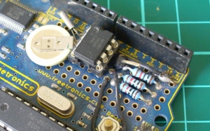
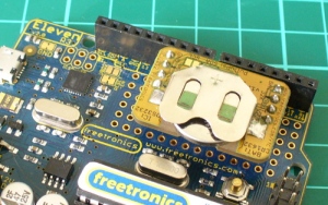
The first stage is to fit your real-time clock. If you are unfamiliar with the operation of real-time clock circuits, check out the last section of this tutorial. You can build a RTC circuit onto a protoshield or if you have a Freetronics Eleven, it can all fit in the prototyping space as such:

If you have an RTC module, it will also fit in the same space, then you simply run some wires to the 5V, GND, A4 (for SDA) and A5 (for SCL):

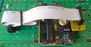
By now I hope you’re thinking “how do you set the time?”. There’s two answers to that question. If you’re using the DS3232 just set it in the sketch (see below) as the accuracy is very good, you only need to upload the sketch with the new time twice a year to cover daylight savings (unless you live in Queensland). Otherwise add a simple user-interface – a couple of buttons could do it, just as we did with Clock Two. Finally you just need to put the hardware on the back of the DMD. There’s plenty of scope to meet your own needs, a simple solution might be to align the control board so you can access the USB socket with ease – and then stick it down with some Sugru:

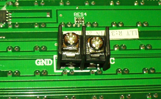
With regards to powering the clock – you can run ONE DMD from the Arduino, and it runs at a good brightness for indoor use. If you want the DMD to run at full, retina-burning brightness you need to use a separate 5 V 4 A power supply. If you’re using two DMDs – that goes to 8 A, and so on. Simply connect the external power to one DMD’s terminals (connect the second or more DMDs to these terminals):

The Arduino Sketch

You can download the sketch from here. Please use IDE v1.0.1 . The sketch has the usual functions to set and retrieve the time from DS1307/3232 real-time clock ICs, and as usual with all our clocks you can enter the time information into the variables in void setup(), then uncomment setDateDs1307(), upload the sketch, re-comment setDateDs1307, then upload the sketch once more. Repeat that process to re-set the time if you didn’t add any hardware-based user interface.

Once the time is retrieved in void loop(), it is passed to the function createTextTime(). This function creates the text string to display by starting with “It’s “, and then determines which words to follow depending on the current time. Finally the function drawText() converts the string holding the text to display into a character variable which can be passed to the DMD.

And here it is in action:

Conclusion

This was a quick project, however I hope you found it either entertaining or useful – and another random type of clock that’s easy to reproduce or modify yourself. We’re already working on another one which is completely different, so stay tuned.

In the meanwhile have fun and keep checking into tronixstuff.com. Why not follow things on twitterGoogle+, subscribe  for email updates or RSS using the links on the right-hand column? And join our friendly Google Group – dedicated to the projects and related items on this website. Sign up – it’s free, helpful to each other –  and we can all learn something.

The post Project: Clock Four – Scrolling text clock appeared first on tronixstuff.

Showcase your project: ultimate cat litter box


This project by Greg is about building a smart litter box for his cats:

We have three cats and the litter is difficult to control. So I had been thinking through a project to build an enclosure. Once I stumbled on Arduino the doors of opportunity were opened. I ordered the electronics and got started on my project right away. So far the Arduino is activating exhaust fans, lightng, and a Lysol spray dispenser. It tracks the number of times the fans are activated and uses a piezo buzzer to alert a filter cleaning. I plan to use it to trigger cleaning based on usage and track each cats potties so we can control their stink before its too late.

A nice video about this project can be found on YouTube.

Arduino Blog 25 Feb 16:00

Track Facebook Likes with Arduino

Using an Arduino Uno equipped with an Ethernet Shield and an LCD Keypad shield, MAKE reader Kedume demonstrates how to create a simple text display for the number of likes on any Facebook page. I think that this is a great project for an Arduino beginner because all you need [...]

Read the full article on MAKE

MAKE » Arduino 09 Feb 17:40

Easy Way Uses Arduino to Translate Subtitles on the Fly

Using the Video Experimenter shield for Arduino, a group in Brazil developed a way to translate live closed captioning to a number of different languages. Called Easy Way Subtitles, the project uses the Video Experimenter Shield to get the closed captioning text from the broadcasted signal and turns it over [...]

Read the full article on MAKE

Data-logging made simple with Arduino

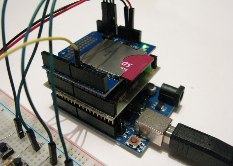
One of the best capabilities provided by Arduino regards its very high modularity, which helps users to quickly translate ideas into physical artifact, as practically demonstrated by Mauro, which shows on his blog how to build a simple data-logger by properly combining different shields. By using few additional components (mainly resistors and buttons) a fully-functional data logger can be easily implemented.

More information can be found here.

[Via: Mauro Alfieri's blog]

Arduino Blog 23 Jan 20:00

Enabling F-bus communications with Arduino

It’s always nice to see how creative makers approach communication issues in DIY projects, and today we would like to highlight the approach followed by Alex, from InsideGadgets.

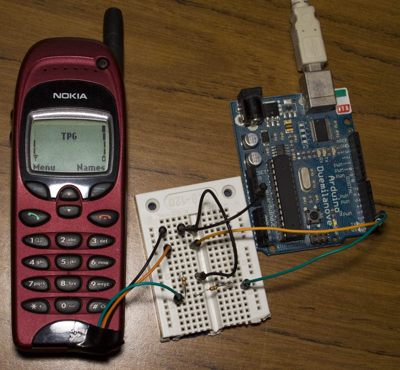
On his website, he provides a detailed tutorial on how to use an old Nokia 6110 (or any derivatives) to send SMS messages by exploiting the Nokia’s F-bus, a simple bi-directional and full-duplex serial protocol.

After considerable reverse engineering work, made possible by useful online documentation, Alex finally managed to send a SMS from his Arduino board, connected to the phone, thanks to AVR libraries made available by AVRFreaks.

More information can be found on InsideGadget.

[Via: Inside Gadgets]