Posts with «led» label

Reading from a Text File and Sending to Arduino

The following tutorial will demonstrate how to Read values from a Text file (.txt, .csv) to blink 1 of 9 LEDs attached to an Arduino. It uses the combination of an Arduino and Processing program to process the file. The Processing program will read the text file in real time, only sending new information to the Arduino.


Components Required

  • Arduino UNO
  • Breadboard
  • 9 LEDs
  • 9 x 330 ohm resistors
  • Wires to connect the circuit
  • USB connection cable: to connect the computer to the Arduino
  • A computer: to run the processing sketch, and to compile / upload the Arduino sketch
  • Processing Program installed on computer
  • Arduino Program installed on the computer
  • A comma separated text file (*.txt).
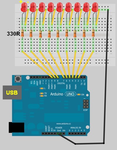

Arduino Layout


The Text File

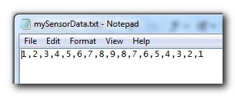
  • Open Notepad or equivalent text file editor, and paste the following data into it.

1,2,3,4,5,6,7,8,9,8,7,6,5,4,3,2,1

  • Save the file on your hard drive. In my case, I have chosen to save the file at this location.

D:/mySensorData.txt

  • It should look like the following screenshot


Additional notes regarding the Text file:
  • Just remember what you call it, and where you saved it, because we will be referring to this file later on in the Processing script.
  • Keep all values on the same line.
  • Separate each number with a comma.
  • The number 1 will blink the first LED which is attached to Pin 2 on the Arduino.
  • The number 9 will blink the last LED which is attached to Pin 10 on the Arduino.


Processing Code

You can download the Processing IDE from this site.

 1
2
3
4
5
6
7
8
9
10
11
12
13
14
15
16
17
18
19
20
21
22
23
24
25
26
27
28
29
30
31
32
33
34
35
36
37
38
39
40
41
42
43
44
45
46
47
48
49
50
51
52
53
54
55
56
57
58
59
60
61
62
63
64
65
66
67
68
69
70
71
72
73
74
75
76
77
78
79

style="color: blue;">import
processing.serial.*;

style="color: blue;">import
java.io.*;

style="color: rgb(43, 145, 175);">int
mySwitch=0;

style="color: rgb(43, 145, 175);">int
counter=0;
String [] subtext;
Serial myPort;


style="color: rgb(43, 145, 175);">void
setup(){

style="color: green;">//Create a switch that will control the frequency of text file reads.


style="color: green;">//When mySwitch=1, the program is setup to read the text file.


style="color: green;">//This is turned off when mySwitch = 0

mySwitch=1;


style="color: green;">//Open the serial port for communication with the Arduino


style="color: green;">//Make sure the COM port is correct

myPort =
style="color: blue;">new
Serial(this,
style="color: rgb(163, 21, 21);">"COM6"
, 9600);
myPort.bufferUntil(
style="color: rgb(163, 21, 21);">'\n'
);
}


style="color: rgb(43, 145, 175);">void
draw() {

style="color: blue;">if
(mySwitch>0){

style="color: green;">/*The readData function can be found later in the code.


style="color: green;"> This is the call to read a CSV file on the computer hard-drive. */

readData(
style="color: rgb(163, 21, 21);">"D:/mySensorData.txt"
);


style="color: green;">/*The following switch prevents continuous reading of the text file, until


style="color: green;"> we are ready to read the file again. */

mySwitch=0;
}

style="color: green;">/*Only send new data. This IF statement will allow new data to be sent to


style="color: green;"> the arduino. */


style="color: blue;">if
(counter<subtext.length){

style="color: green;">/* Write the next number to the Serial port and send it to the Arduino


style="color: green;"> There will be a delay of half a second before the command is


style="color: green;"> sent to turn the LED off : myPort.write('0'); */

myPort.write(subtext[counter]);
delay(500);
myPort.write(
style="color: rgb(163, 21, 21);">'0'
);
delay(100);

style="color: green;">//Increment the counter so that the next number is sent to the arduino.

counter++;
}
style="color: blue;">else
{
//If the text file has run out of numbers, then read the text file again in 5 seconds.
delay(5000);
mySwitch=1;
}
}


style="color: green;">/* The following function will read from a CSV or TXT file */


style="color: rgb(43, 145, 175);">void
readData(String myFileName){

File file=
style="color: blue;">new
File(myFileName);
BufferedReader br=
style="color: blue;">null
;

try{
br=
style="color: blue;">new
BufferedReader(
style="color: blue;">new
FileReader(file));
String text=
style="color: blue;">null
;


style="color: green;">/* keep reading each line until you get to the end of the file */


style="color: blue;">while
((text=br.readLine())!=
style="color: blue;">null
){
/* Spilt each line up into bits and pieces using a comma as a separator */
subtext = splitTokens(text,
style="color: rgb(163, 21, 21);">","
);
}
}
style="color: blue;">catch
(FileNotFoundException e){
e.printStackTrace();
}
style="color: blue;">catch
(IOException e){
e.printStackTrace();
}
style="color: blue;">finally
{
try {

style="color: blue;">if
(br != null){
br.close();
}
}
style="color: blue;">catch
(IOException e) {
e.printStackTrace();
}
}
}

I used this site to highlight and format my code.

Once you have copied the text above into the Processing IDE, you can now start working on the Arduino code as seen below.


Arduino Code

You can download the Arduino IDE from this site.

Copy and paste the following code into the Arduino IDE.

 1
2
3
4
5
6
7
8
9
10
11
12
13
14
15
16
17
18
19
20
21
22
23
24
25
26
27
28
29
30
31
32
33
34
35
36
37
38
39
40
41
42
43
44
45
46
47
48
49

style="color: green;">/* This program was created by ScottC on 8/5/2012 to receive serial


style="color: green;">signals from a computer to turn on/off 1-9 LEDs */


style="color: rgb(43, 145, 175);">void
setup() {

style="color: green;">// initialize the digital pins as an output.

pinMode(2, OUTPUT);
pinMode(3, OUTPUT);
pinMode(4, OUTPUT);
pinMode(5, OUTPUT);
pinMode(6, OUTPUT);
pinMode(7, OUTPUT);
pinMode(8, OUTPUT);
pinMode(9, OUTPUT);
pinMode(10, OUTPUT);

style="color: green;">// Turn the Serial Protocol ON

Serial.begin(9600);
}


style="color: rgb(43, 145, 175);">void
loop() {

style="color: rgb(43, 145, 175);">byte
byteRead;


style="color: green;">/* check if data has been sent from the computer: */


style="color: blue;">if
(Serial.available()) {


style="color: green;">/* read the most recent byte */

byteRead = Serial.read();

style="color: green;">//You have to subtract '0' from the read Byte to convert from text to a number.

byteRead=byteRead-
style="color: rgb(163, 21, 21);">'0'
;


style="color: green;">//Turn off all LEDs if the byte Read = 0


style="color: blue;">if
(byteRead==0){

style="color: green;">//Turn off all LEDS

digitalWrite(2, LOW);
digitalWrite(3, LOW);
digitalWrite(4, LOW);
digitalWrite(5, LOW);
digitalWrite(6, LOW);
digitalWrite(7, LOW);
digitalWrite(8, LOW);
digitalWrite(9, LOW);
digitalWrite(10, LOW);
}


style="color: green;">//Turn LED ON depending on the byte Read.


style="color: blue;">if
(byteRead>0){
digitalWrite((byteRead+1), HIGH);
style="color: green;">// set the LED on

}
}
}

Additional Information:
  • The Arduino code will still work without the processing program. You can open the serial monitor window to send the commands to the Arduino manually. In fact, if you encounter any problems, I would suggest you do this. It will help to identify the root cause of the problem (ie Processing or Arduino Code, or physical connections).
  • If you choose to use the Serial Monitor feature of the Arduino IDE, you cannot use the Processing program at the same time.

Once you have assembled the Arduino with all the wires, LEDs, resistors etc, you should now be ready to put it all together and get this baby cranking!


Connecting it all together

  • Connect the USB cable from your computer to the Arduino, and upload the code.
  • Keep the USB cable connected between the Arduino and the computer, as this will become the physical connection needed by the Processing Program
  • Make sure that you have the text file in the correct location on your hard drive, and that it only contains numbers relevant to the code provided (separated by commas).
  • Run the Processing program and watch the LEDs blink in the sequence described by the text file.
  • You can add more numbers to the end of the line, however, the processing program will not be aware of them until you save the file. The text file does not have to be closed.
Other programs can be used to create text file, but you will need the processing program to read the file and send the values to the Arduino. The Arduino will receive each value and react appropriately.

SIMILAR PROJECT: Use a mouse to control the LEDs on your Arduino - see this post.


An alternative Processing Sketch

This Processing sketch uses the loadStrings()method instead of the FileReader method used in the first sketch. This sketch also provides better control over sending the values to the Arduino. When the sketch first loads, the application window will be red. By clicking your mouse inside the window, the background will turn green and the file will be imported and sent to the Arduino, with every value being sent at half second intervals. If you update the text file and save, only new values will be transmitted, however, if you want the entire file to transmit again, you can press the window once (to reset the counter), and then again to read the file and send the values again from the beginning of the file.
I personally like this updated version better than the first, plus I was inspired to update this blog posting due to the fact that some people were having problems with the FileReader method in the first sketch. But both sketches should work (they worked for me).


 1
2
3
4
5
6
7
8
9
10
11
12
13
14
15
16
17
18
19
20
21
22
23
24
25
26
27
28
29
30
31
32
33
34
35
36
37
38
39
40
41
42
43
44
45
46
47
48
49
50
51
52
53
54
55
56
57
58
59
60
61
62

style="color: rgb(0, 128, 0);">/* TextFile Sender: Written by Scott C on 5th April 2013


style="color: rgb(0, 128, 0);"> using Processing Version 2.0b8 */


import processing.serial.*;

Serial comPort;

style="color: rgb(43, 145, 175);">int
counter=0;
style="color: rgb(0, 128, 0);">// Helps to keep track of values sent.


style="color: rgb(43, 145, 175);">int
numItems=0;
style="color: rgb(0, 128, 0);">//Keep track of the number of values in text file

boolean sendStrings=
style="color: rgb(0, 0, 255);">false
;
style="color: rgb(0, 128, 0);">//Turns sending on and off

StringLoader sLoader;
style="color: rgb(0, 128, 0);">//Used to send values to Arduino


style="color: rgb(43, 145, 175);">void
setup(){
comPort =
style="color: rgb(0, 0, 255);">new
Serial(
style="color: rgb(0, 0, 255);">this
, Serial.list()[0], 9600);
background(255,0,0);
style="color: rgb(0, 128, 0);">//Start with a Red background

}


style="color: rgb(43, 145, 175);">void
draw(){
}


style="color: rgb(43, 145, 175);">void
mousePressed() {

style="color: rgb(0, 128, 0);">//Toggle between sending values and not sending values

sendStrings=!sendStrings;


style="color: rgb(0, 128, 0);">//If sendStrings is True - then send values to Arduino


style="color: rgb(0, 0, 255);">if
(sendStrings){
background(0,255,0);
style="color: rgb(0, 128, 0);">//Change the background to green


style="color: rgb(0, 128, 0);">/*When the background is green, transmit


style="color: rgb(0, 128, 0);"> text file values to the Arduino */

sLoader=
style="color: rgb(0, 0, 255);">new
StringLoader();
sLoader.start();
}
style="color: rgb(0, 0, 255);">else
{
background(255,0,0);
style="color: rgb(0, 128, 0);">//Change background to red


style="color: rgb(0, 128, 0);">//Reset the counter

counter=0;
}
}


style="color: rgb(0, 128, 0);">/*============================================================*/


style="color: rgb(0, 128, 0);">/* The StringLoader class imports data from a text file


style="color: rgb(0, 128, 0);"> on a new Thread and sends each value once every half second */


style="color: rgb(0, 0, 255);">public

style="color: rgb(0, 0, 255);">class

style="color: rgb(43, 145, 175);">StringLoader
extends Thread{


style="color: rgb(0, 0, 255);">public
StringLoader(){

style="color: rgb(0, 128, 0);">//default constructor

}


style="color: rgb(0, 0, 255);">public

style="color: rgb(43, 145, 175);">void
run() {
String textFileLines[]=loadStrings(
style="color: rgb(163, 21, 21);">"d:/mySensorData.txt"
);
String lineItems[]=splitTokens(textFileLines[0],
style="color: rgb(163, 21, 21);">","
);
numItems=lineItems.length;

style="color: rgb(0, 0, 255);">for
(
style="color: rgb(43, 145, 175);">int
i = counter; i<numItems; i++){
comPort.write(lineItems[i]);
delay(500);
comPort.write(
style="color: rgb(163, 21, 21);">"0"
);
}
counter=numItems;
}
}


ScottC 09 May 14:09

Classy fashionable necklaces using lilypad

Fashionable Technology Performance_ Interactive Necklace from Sylvia Yang on Vimeo.

In an age of geekifying, everything electronics entering fashion is not something new. But the subtle difference between doing something classy and over doing is set apart by the talented designer Sylvia Yang.

A designer’s draft of the design + components (we can see a lilypad there!) is shown here:

[Via: www.sylvia-yang.com]

Getting Started with Android and Arduino

Writing applications on Android is cool but writing applications on Android that can talk to the physical world is totally awesome. I recently bought a Seeduino ADK Board, which is actually a clone of an Arduino board that has support for the Android Accessory Development Kit. You can find more information about Seeduino here.

[...]
Android + Arduino 25 Mar 17:13
adk  android  arduino  led  red pill  

Psychedelic Sphere of LEDs

The friend of a performer created this optical light display of 256 LEDs that can be programmed to create some fascinating displays.  The ball has 16 panels, which are not only the circuit boards, but the structural support of the ball as well. The central brain is provided by an Arduino powered by two AA batteries.  For more information, see the full project details (the site may be temporarily down).

Popular LED Projects:

Hack n Mod 07 Jan 16:31

NPN Transistor Sketch (P2N2222AG) using PWM

We are now going to build a simple circuit to test out the P2N2222AG transistor in the sparkfun inventor's kit. You can also buy this transistor from RS-online.

Here are the components that you will need.
  • 1 x Arduino UNO
  • 1 x Breadboard
  • 1 x P2N2222AG transistor
  • 3 x LEDs  (1 x Red LED, 2 x Yellow LEDs)
  • 3 x 330 ohm Resistors
  • Wires to connect it all together.
Here is the Fritzing sketch:


We will use Pulse width modulation (PWM) to fade the LEDs in and out. 
Load the "Fading" example into the Arduino. (File>Examples>Analog>Fading)


I used this sketch to help me understand how electricity flowed through the transistor by disconnecting a wire here and there. I am not sure if this is advisable, so do this at your own risk. If you are an electrical engineer, feel free to comment. Please let me know if this is "risky" business.
I have had no formal training in electronics, so don't blame me if your arduino, or transistor blows up !
But from what I understand, I cannot see any harm in disconnecting wires with this particular circuit.
Please note, that I would disconnect the power to the arduino before modifying the wires.

PC Fan hack lets you scra... scra... scratch analog audio, ah-yeah (video)

Digital DJ controllers let would-be grandmasters get up to all sorts of fancy new tricks, but if you're one of those old dogs who can't be taught, then this PC-fan-come-DJ-turntable might tickle your fancy. Connected to an old-school personal cassette via an Arduino, with a little voltage level smoothing in the mix, moving the fan "scratches" the audio, by controlling the speed of the tape player. The initial plan was to have the fan spinning with the music, like a real turntable, but as you'll know if you've ever caught your finger in one of these things, it's probably best it didn't work out. Despite its home-made charms, one final flourish is VU style LEDs for some mixer-style visual feedback. Alas, there's no built in cross-fader, so don't start work on that DMC routine just yet.

Continue reading PC Fan hack lets you scra... scra... scratch analog audio, ah-yeah (video)

PC Fan hack lets you scra... scra... scratch analog audio, ah-yeah (video) originally appeared on Engadget on Tue, 22 Nov 2011 04:29:00 EST. Please see our terms for use of feeds.

Permalink | Email this | Comments
Engadget 22 Nov 09:29
arduino  audio  dj  hack  led  pc fan  pcfan  scratch  turntable  video  

LED (F)Light Suit: Ramping Up

I've been mesmerized by bouncing red LED's since the early '80s. LED's were mostly red, needle-style VU meters were on the outs, we hadn't yet graduated to green-yellow-red meters, and I grew a special place in my heart for those bouncing red lights. We also had KITT and the Cylons: bouncing red lights were and still are awesome ("rad" had not been invented yet).

I put together a black flight suit with red EL-wire segments for Burning Man in 2008 but did not have time to build the sequencer and control system I envisioned, so it was an on/off affair, or it pulsated to the music before the small batteries died.

Working on a suit for this year's burn, I've decided to return to the original concept-- red LED's-- and am working on the major areas now:
  • Suit electronics: Arduino core, I2C port expander w/PWM output using PCA9685 16-channel, 12-bit PWM I2C-bus LED controller driving power MOSFETs, one per segment. There are 17 segments in my design, so I'll use the port expander and then another spare pin to trigger the 17th channel.
  • Audio metering: I have a MaceTech Shifty VU shield working but I wonder about adjusting levels on the fly, and how to best get a mic input to it or something similar. There will be other modes for sequencing the lights, but bouncing VU meter is the primary mode I'm looking for.
  • Segment planning: location and length of each segment, power lead routing, attachment to suit. This is going well, with the first seven (of 22) segments cut and tested last night from my first 5M strip from DealExtreme; the suit will need 53' of light strip so I've ordered more.
  • Power: rechargable 12V power packs are easy to get; not sure how to recharge them on the Playa.
  • Remote control: would like to have a small, wireless remote to control modes and mode parameters.
  • The program: I have a list of modes I'd like to switch between, some of which have parameters I'll want to adjust on the fly. Ideally I'll be able to edit the program during the day if I come up with new ideas while I'm in BRC.

n/a