Posts with «led» label

Lite Brites fade, but LED clocks are forever

Ahh, the Lite Brite.

What could be more fun than pushing dozens of little plastic pegs through a piece of black paper in order to create a pixelated, though colorful image? Well, I can think of quite a few things more engaging than that, and luckily so can [Lonnie Honeycutt] over at MeanPC.

While contemplating what to build with a pile of LEDs, his daughter came into the room with her portable Lite Brite. He thought that the pegs she was using looked awfully similar to the LEDs on his desk, so he did some test fitting and was surprised to see that they fit almost perfectly.

[Lonnie] thought that the toy would make an excellent clock, and his daughter happily agreed to let Dad do some tinkering. A few hours, an Arduino, and some Charlieplexing later, he had a nice looking clock that his kids were sure to enjoy.

If you’re interested in seeing more about how constructed, be sure to check out his YouTube channel and Instructable, where he happily provides all of the build details.


Filed under: arduino hacks, led hacks, toy hacks

Building an LED suit

[Rob] has been hard at work designing and building this LED suit which he can wear to parties. He’s got it working, although right now it’s just a pair of pants. It reacts to sound, and has the potential to be controlled from a smartphone via Bluetooth. You’ll find a video description of the build embedded after the break.

The planning started off by selecting driver hardware for the LEDs. [Rob] wanted the suit to pulse to the music in the room so he grabbed an MSGEQ7 chip. When connected to a microphone and opamp this chip will output a signal which can be used as a VU meter. He built the hardware into an Arduino shield, then got to work on the LED driver board. He’s using LED strips, but they’re not individually addressable. Instead he cut loops which wrap around the wearer’s legs. Each loop connects the pins of a TLC5947 LED driver chip which sinks a constant current and offers PWM abilities. He’s using PNP transistors on the high side.

For anyone that’s ever worked in a Tyvek suit before you’ll know they don’t breathe. Sweat will literally be pouring off of you. And we’d bet that’s what cause the short that burned the back of [Rob's] leg at a recent party. Then again, your light-up pimp coats are going to be hot to wear too.


Filed under: led hacks, wearable hacks
Hack a Day 16 Aug 20:01

Led as light sensor [Arduino]

If you connect led in the opposit way he can act as light sensor:

positive leg to analog pin

negative leg to 5V

You can use that for some things, but he not sensetive as LDR,

ןf you use a for example a green led he not "see" well red light

If you use charlieplexing method you can control one led to light and as a light sensor.

The idea is like this:

Two wires connect the led to two analog pins.

To light the led you set the two analog pins as digital output and one high one low. 

read more

blink(1) the USB RGB LED Status Light

The wonderful gang at ThingM (makers of the blinkM smart LED) have announced an interesting new product is in the works, the blink(1) programmable USB RGB LED status indicator. Plug the little open source nub into most any USB port – laptop, desktop, server, some Android phones, DD-WRT router – and then you can use apps (or create your own) to make the blink(1) LED light up to indicate an event. A tweet just mentioned me? Steady green light. Email from my wife? Three blue blinks. CPU overheating? Red alert!

From the ThingM blog:

ThingM has just launched a Kickstarter for “blink(1)”. A USB RGB LED that builds on our BlinkM Smart LED. It’s a super status light that packs three dimensions of information (color, brightness and pattern) into a single tiny package that fits into any USB port on nearly every device.
It makes it incredibly easy to connect any data source in the cloud or on your computer to a full-color RGB LED so you can know what’s happening without checking any windows, going to any websites, or typing any commands.

I can’t wait to get my hands on one – the Kickstarter is nearly funded, so I’m optimistic – to play around with the development tools. I’d love, for example, to have the Blink(1) tell me when a Renderman render has completed, or if I have a meeting in five minutes.

Blink(1), the USB RGB LED by ThinkM


Incredible RGB LED Cube Tutorial


We’ve seen our fair share of LED light cubes before, but what makes this one different is its incredibly detailed, step-by-step tutorial.   The creator of this light show previously made a one color LED light cube and shared the trials, tribulations and instructions.  He has since decided to go multi-color, again while challenging himself and learning some new tricks along the way.


The project requires 512, 10mm RGB LEDs and an Arduino compatible microcomputer. The creator used wooden strips to create vertical panels of LEDs rather than horizontal layers for ease of building. The building and soldering took about one weekend and the software took about 70 hours. The author saves you time by providing most of the code for you.  Learn how to  fbuild your own RGB LED cube!

Popular LED Projects:

Hack n Mod 11 Jul 11:07

Bike alert tells drivers to back off

Bicycle commuters are often in a battle with drivers for space on the road. [Hammock Boy] does all of his commuting on two human-powered wheels, and is quite interested in not getting hit by a car. He decided to ply his hobby skills to build a device that helps keep him safe. It’s not just a tail light, it’s a sensor that shines brighter the closer a car is to the back of the bike.

The sensor portion is the ultrasonic range finder seen in the center of the protoboard. Surrounding it is a set of LEDs. Each is individually addressable with the whole package controlled by an Arduino. The sketch measures the distance between the back of the bike and whatever’s behind it. If there’s nothing, one Red led is illuminated. If there is an object, the lights shine brighter, and in different patterns as the distance decreases.

Certainly the next iteration could use a standalone chip without the need for the whole Arduino. This could even work with two battery cells and no voltage regulator. We also think the use of any other color than Red LEDs is suspect but we do love the concept.


Filed under: transportation hacks

Starbot

Primary image

What does it do?

Shines toward Spectator

The Starbot is a custom robot made for one of my sons. It is a star that shines and rotates to where the spectator is.

My son found this wooden star-on-a-stick somewhere and played around with it. After a while he came to me and said it would be cool if this star would shine whenever somebody comes close to it.

Bam! Here we go. This is a perfect question for a geek dad. Of course we can! So this little kid and I elaborated a bit more and out came this robot named Starbot.

Cost to build

$40,00

Embedded video

Finished project

Number

Time to build

8 hours

Type

URL to more information

Weight

200 grams

read more

TicTocTrac: track your perception of time

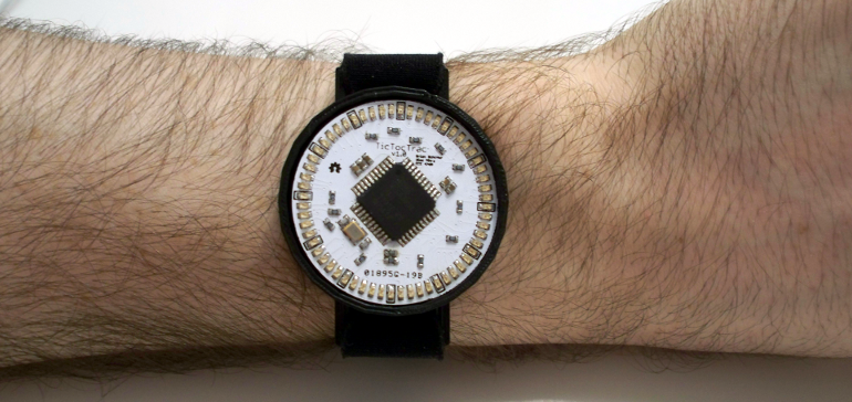
Brian Schiffer and Sima Mitra, from Cornell University, propose a very nice wristwatch that allows you to keep track of your time perception, using a method known as duration production: TicTocTrac.

Human perception of time is typically distorted, due to the different amount of information and experiences acquired everyday. TicTocTrac lets you to estimate your own perception, first by signaling the perceived duration of a given event and, then, by comparing it with the actual event duration. Finally, all the information can easily be saved to a micro SD card.

The hardware is based on a Atmega32u4, a DS3234S real-time clock and several leds to display time, while the software part is mostly based on Arduino’s DS3234S RTC library.

More information can be found here.

[Via: TicTocTrac]

Mouse Controlling Arduino LEDs


Use a mouse to control LEDs attached to an Arduino. This project uses the processing language to transmit the mouse coordinates to the Arduino, which then uses this information to turn on some LEDs. Please see the video below to see it in action.


Components Required for this project:

  • Arduino UNO
  • Breadboard
  • 9 LEDs
  • 9 x 330 ohm resistors
  • Wires to connect the circuit
  • USB connection cable: to connect the computer to the Arduino
  • A computer: to run the processing sketch, and to compile / upload the Arduino sketch
  • Processing Program installed on computer
  • Arduino Program installed on the computer

Arduino Sketch


This was made using Fritzing.

Arduino Code

You can download the Arduino IDE from this site.

 1
2
3
4
5
6
7
8
9
10
11
12
13
14
15
16
17
18
19
20
21
22
23
24
25
26
27
28
29
30
31
32
33
34
35
36
37
38
39
40
41
42
/* This program was created by ScottC on 9/5/2012 to receive serial 
signals from a computer to turn on/off 1-9 LEDs */

void setup() {
// initialize the digital pins as an output.
pinMode(2, OUTPUT);
pinMode(3, OUTPUT);
pinMode(4, OUTPUT);
pinMode(5, OUTPUT);
pinMode(6, OUTPUT);
pinMode(7, OUTPUT);
pinMode(8, OUTPUT);
pinMode(9, OUTPUT);
pinMode(10, OUTPUT);
// Turn the Serial Protocol ON
Serial.begin(9600);
}

void loop() {
byte byteRead;

/* check if data has been sent from the computer: */
if (Serial.available()) {

/* read the most recent byte */
byteRead = Serial.read();
//You have to subtract '0' from the read Byte to convert from text to a number.
byteRead=byteRead-'0';

//Turn off all LEDS
for(int i=2; i<11; i++){
digitalWrite(i, LOW);
}

if(byteRead>0){
//Turn on the relevant LEDs
for(int i=1; i<(byteRead+1); i++){
digitalWrite(i+1, HIGH);
}
}
}
}

The code above was formatted using this site.


Processing Code

You can download the Processing IDE from this site.

 1
2
3
4
5
6
7
8
9
10
11
12
13
14
15
16
17
18
19
20
21
22
23
24
25
26
27
28
29
30
31
32
33
34
35
36
37
38
39
40
41
42
43
44
45
46
47
48
49
50
51
52
53
54
//Created by ScottC on 12/05/2012 to send mouse coordinates to Arduino

import processing.serial.*;

// Global variables
int new_sX, old_sX;
int nX, nY;
Serial myPort;

// Setup the Processing Canvas
void setup(){
size( 800, 400 );
strokeWeight( 10 );

//Open the serial port for communication with the Arduino
//Make sure the COM port is correct
myPort = new Serial(this, "COM6", 9600);
myPort.bufferUntil('\n');
}

// Draw the Window on the computer screen
void draw(){

// Fill canvas grey
background( 100 );

// Set the stroke colour to white
stroke(255);

// Draw a circle at the mouse location
ellipse( nX, nY, 10, 10 );

//Draw Line from the top of the page to the bottom of the page
//in line with the mouse.
line(nX,0,nX,height);
}


// Get the new mouse location and send it to the arduino
void mouseMoved(){
nX = mouseX;
nY = mouseY;

//map the mouse x coordinates to the LEDs on the Arduino.
new_sX=(int)map(nX,0,800,0,10);

if(new_sX==old_sX){
//do nothing
} else {
//only send values to the Arduino when the new X coordinates are different.
old_sX = new_sX;
myPort.write(""+new_sX);
}
}

The code above was formatted using this site.

Cheap Arduino-based Thermal Flashlight

Thermal flashlight is a widely used technique to “paint temperature with light”: by using a temperature sensor and a RGB flashlight, it is possible to illuminate a surface with a proper tonality, which, in turn, can be acquired by means of a standard camera. It’s main use is to find thermal leaks in houses and buildings.

In their article, PLOTS‘ staff propose and describe a nice and cheap way to build your own thermal flashlight with Arduino, together with a clear introduction to the subject.

Read more here.

Via: The Public Laboratory for Open Technology and Science


Arduino Blog 09 May 21:18
camera  enviroment  led  led(s)  rgb  themal  thermal