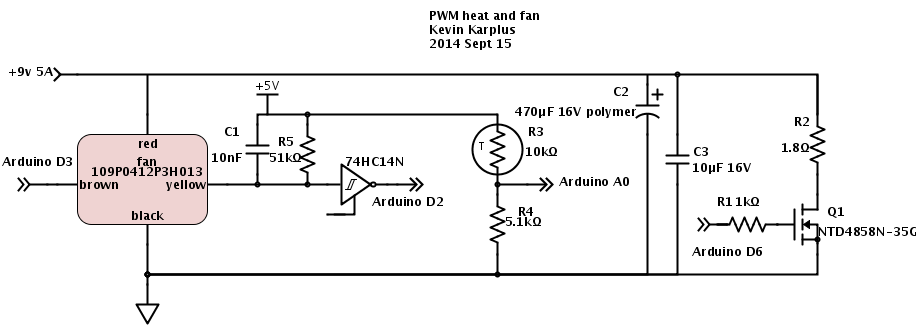
Here is the circuit for the heater and fan that I’ve been developing for incubator project for the freshman design course:

Here is the circuit I’ve been using for playing with control loops. (The 74HC14N Schmitt trigger inverter does not have an enable input, but SchemeIt has a very limited and idiosyncratic set of schematic symbols, so I used the closest one.)
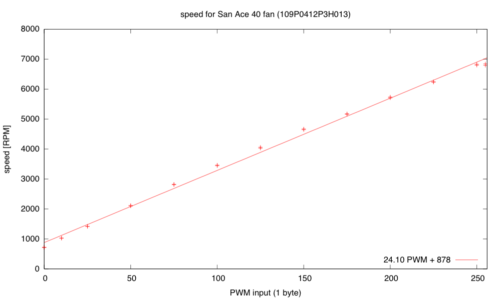
Yesterday and this morning, when I was developing the controller software for the fan and resistive heater, I ran into a lot of problems with overshoot when changing the setpoints. For the fan controller I wrote “One thing that helped was not accumulating integral error when the PWM signal was pinned at the lowest or highest values.” I also switched to using RPM rather than pulse duration as the measured variable, because RPM is nearly linear with the PWM input (RPM approximately 24.1 PWM + 878). Another thing “that helped was to make a guess at the target PWM setting when the setpoint was changed (using d RPM/ d PWM =24 and the current PWM setting and RPM value), then setting the cumulative error to what it would be in steady state at that PWM. I then set the PWM to five times as far from current PWM as the target PWM to make the transition as fast as possible without increasing overshoot, making sure to clip to the legal 0..255 range.” Because I have a reasonable model for RPM as a function of PWM, it was easy to estimate what the target PWM should be so that the cumulative error from the integrator would set the PWM value correctly once the error dropped enough that the desired PWM value was no longer pinned at the limits.
Today I decided to do a little reading to find out what other people have done about the problem of the controller overshooting when the actuator hits its limits. It turns out that the phenomenon is know as “integrator windup“, and the two solutions I came up with are standard solutions. Turning off the error accumulation when the actuator is at its limit and more movement in that direction is desired is known as “conditional integration” and guessing the correct setting for the cumulative error on setpoint change is a form of “back calculation”. There are more sophisticated forms of back calculation that I might want to try implementing. (I found a better explanation of the anti-windup scheme, which I might base my next implementation on—basically it gradually reduces the cumulative error to 0 as long as the desired setting for the actuator is past its limits.)
The temperature controller has been harder for me to tune, for several reasons:
- The response time is very long. Instead of oscillating around 5Hz, the period seems to be more like 90 seconds. This means that it takes a long time to see whether an adjustment to the parameters makes a difference.
- The temperature at the thermistor is dependent on the temperature at the resistor. The thermal mass and thermal resistance act like an RC circuit (with temperature analogous to voltage, and power dissipated analogous to current). Adjusting the power to the resistor via PWM changes the rate at which the temperature increases. It also changes the eventual equilibrium temperature, but the PWM control is more directly of the rate of temperature change.
- The heatsink and resistor continue to warm the air and the measuring thermistor even after all power to the resistor is cut off, so there is a big danger of overshoot whenever the setpoint temperature is increased.
- The control is asymmetric—dumping 40W of power into the resistor heats it up fairly fast, but heat is only slowly dissipated when power is turned off. Running the fan fast helps a little here, slowing down the temperature rise and speeding up the cool down, but once I put the whole thing in a closed box, it will be very difficult to cool things off if the box gets too warm. This makes overshoot in the positive direction a serious problem.
- The temperature measurements are only about 0.1°C resolution, and the noise on the ADC is about ±4LSB, so it will be difficult to get tight temperature control, even with a perfectly tuned controller.
- I don’t have a simple model of what the steady-state thermistor temperature will be given the PWM input, so I’ve had difficulty coming up with a guess about the eventual PWM value for resetting the cumulative error on a setpoint change. I have a model for the resistor temperature in still air, but the fan makes a huge difference, both in the thermal resistance (and so both the equilibrium temperature and time constant of the resistor heating) and in the coupling between the resistor and the thermistor.
I still have a lot of things left over from a couple of days ago, and I’ve added some new things to the list.
- Put the whole thing into a styrofoam box, to see whether extra venting is needed to allow things to cool down, and to see how tightly temperature can be controlled. I’ve put stuff in the box, but I can’t close the box with the stuff sticking out, so it doesn’t really count.
- Design and build baffling for the fan to get better airflow in the box. I’ve made a little paper and wire baffle, to get better air flow over the resistor, but I’ve not done the full baffling to get good airflow in the box.
- Figure out how to get students to come up with workable designs, when they are starting from knowing nothing. I don’t want to give them my designs, but I want to help them find doable subproblems. Some of the subproblems they come up with may be well beyond the skills that they can pick up in the time frame of the course. The more I work on this project, the more I realize that I and the students will have to be happy with them having explored the options, without getting all the problems solved.
- Find a smaller bread board or prototype board to put the controller on—my current bread boards are all 6.5″ long, and the box only has room for 6″, especially since I put the resistor in the center of the 6″×12″ aluminum plate, which just fits the box. I suppose I could drill a couple more holes in the plate and mount the resistor off center, but I rather like the idea of building the controller as an Arduino shield, so that the Arduino + controller is a single unit.
- Another possibility is to drill a hole in the styrofoam box and run cables through the box for the resistive heater, the fan, and the thermistor. Even if the grounds are connected outside the box, this is only 8 wires. Putting the control electronics outside the box would reduce the clutter in the box and make tweaking easier.
- Add some low-pass filtering to the temperature measurement to reduce noise. Just adding 4 measurements in quick succession would reduce the noise and give the illusion of extra precision.
- The fan controller occasionally has a little glitch where the tachometer either misses a pulse or provides an extra one (I think mainly an extra one due to ringing on the opposite edge). I could try reducing this problem in three ways: 1) changing which edge I’m triggering on, 2) using more low-pass filtering before the Schmitt trigger in the edge detector, or 3) using median filtering to throw out any half-length or double-length pulses, unless they occur as a pair. (Hmm, the half-length pulses would occur as a pair, so this might not help unless I go to median of 5, which would be a lot of trouble.)
- Improve my modeling of the thermal system, so that I can do more reasonable back calculation on setpoint change.
- Consider using a PID controller for the temperature to get faster response without overshoot. (If I can reduce the noise problem.)
- Improve my anti-windup methods for both thermal and fan controllers, to reduce overshoot.
Filed under:
freshman design seminar Tagged:
Arduino,
control loop,
fan,
incubator,
integrator windup,
PID controller,
power resistor,
PWM,
tachometer,
thermistor