Go to the Milwaukee Maker Faire and Solve the Laser Maze
 If you want to channel your inner Catherine Zeta-Jones and give it a shot yourself, take a crack at the Laser Maze.

 If you want to channel your inner Catherine Zeta-Jones and give it a shot yourself, take a crack at the Laser Maze.
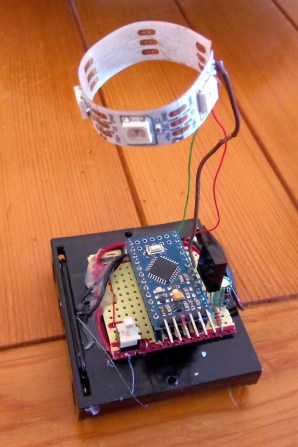
Now that I have a power resistor and heatsink, and have verified that my power supply is capable of delivering 50W, I can try making a thermal control system for an incubator box as I hope to get the freshman design class to do.
Before building a complete control system and tuning a proportional, PI, or PID controller, I decided to check each of the components:
I started out hooking up the nFET and the 1.8Ω resistor and making sure that the nFET did not get too hot. It seems to be ok. When I was using the 8.2Ω resistor, I measured the voltage drop across the resistor and the across the nFET, getting a 57.6mV drop from drain to source, with a current of about 9.024V/8.21ohm = 1.099A. That’s about a 52mΩ on-resistance, and I was expecting more like 7mΩ–10mΩ. My gate voltage was around 5V (bigger than the 4.5V of the data sheet), which should have given me lower on-resistance. The only things I can think of are that I had more wiring resistance than I realized (quite likely, but not likely enough to add over 40mΩ), and that I was measuring around 1A, not around 10A, so perhaps there is a small-voltage effect that I don’t know about.
I should probably test the voltage drop again with 1.8Ω resistor, and see whether the on-resistance is still so high. Better probe placement may get me more accurate voltage measurements also.
The fan runs fine at 9.212V at about 6850 RPM. Setting the PWM input line of the fan to 0 drops the speed to about 710RPM, and setting the PWM duty cycle to a half sets the speed at about 4120RPM. The fan is a bit noisy for such a tiny fan at the highest speed setting, but reasonably quiet at lower speeds. I suspect that bolting the fan to a piece of masonite as a baffle would reduce the fan noise, as I think quite a bit of it was from vibration between the case of the fan and the metal plate it was sitting on.
The tachometer on the fan provides an open-collector output that I read with an interrupt input on the Arduino (pin 2, interrupt 0). I recorded the time between interrupts and converted it an RPM measurement. The tachometer worked fine when I was just using the fan, or when the resistor was either completely off or completely on, but when I tried using PWM on the resistor, the tachometer readings became nonsense.
I looked at the tachometer signal with my oscilloscope and saw that the PWM transitions for the resistor resulted in huge spikes in the tachometer output that triggered extraneous interrupts. I suspected noise coupled through the power supply. Adding a 10µF bypass capacitor to the 9V power supply to the fan reduced the problem considerably, and a 470µF aluminum polymer electrolytic cleaned up the power supply even more. The 10µF alone was enough to eliminate the extraneous spikes in the middle.
I think that I should try adding some gate resistance to the nFET to slow down the rise and fall of the PWM signal a little, to reduce the inductive spikes and make the bypass capacitors more effective.
I noticed that I was still getting some readings that were half the duration that I was expecting. These could have been caused by ringing at the other transition of the tachometer pulse, so I tried eliminating the ringing by adding some capacitance to the line and changing the pullup resistor. These attempts were not very successful, so I decided that hysteresis was needed. I put a Schmitt trigger between the open-collector output and the Arduino interrupt input, and the signal got a lot cleaner. There were occasional double pulses at one edge, though, but I found that adding a 1nF to 10nF capacitor in parallel with the pullup resistor for the open collector output smoothed out the high frequency noise enough to get clean, single transitions out of the Schmitt trigger.
I hooked up the thermistor in a voltage divider with 5.1kΩ on the other leg (which maximizes the dV/dT sensitivity at 40.1°C). I used the parameters on the data sheet to plot a calibration curve for the thermistor:
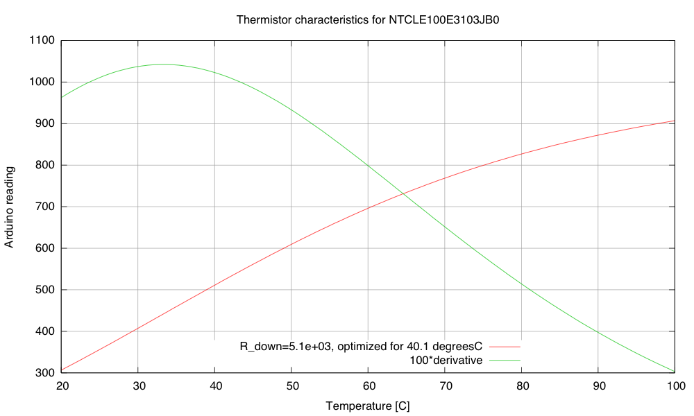
Calibration and sensitivity curves for the thermistor, based on the data sheet and a 5.1kΩ pulldown resistor.
The maximum sensitivity of the thermistor circuit is around 33.3 degrees C (~10.4 Arduino LSB/°C). That’s not a very high sensitivity, particularly given the noise of the ADC. Note that maximizing the slope at 40.1 °C is not the same thing and having the maximum of the slope at 40.1°C. If the maximum of the slope was at 40.1°C, the slope there would be less than it is in this plot.
My son wonders why I’m using the Arduino board for this project, rather than the FRDM-KL25Z board that I use for the circuits class or the Teensy 3.1 ARM development board. The ARM processors have more power, more memory, and much better analog-to-digital converters—and the KL25Z board is cheaper. If I were doing this project for myself, I would certainly prefer the KL25Z board. But it is a little harder to get a beginner started on that board—just getting the first program onto the board is a pain if you don’t have a Windows machine (due to the broken bootloader the P&E Micro wrote). There are instructions now for replacing the firmware from a Linux system, but I’ve not checked yet whether these instructions work from a Mac. Even once you get working firmware onto the boards, the development environments are not beginner-friendly. Well, that is certainly true of the MBED environment or bare-metal ARM environment for the KL25Z boards, but the Teensy 3.1 board supposedly can be programmed from a plugin for the Arduino IDE, which might be simple enough for beginners. This is something for me to look into more.
Of course, one reason I’m using the Arduino Uno or Sparkfun RedBoard is that they are 5V processors, and most of the power nFETs I’ve looked at need 4.5V on the gate to turn on fully. There are power nFETs now with lower gate voltages, but most of them are only available as surface-mount devices. I don’t want to have to add an extra transistor or buffer chip as a level changer for the PWM circuit.
The problem is that these students will be brand new to programming, brand new to electronics, and brand new to engineering—and the course is only a 2-unit course, not a full 5-unit course, so the total time students are expected to spend on the course is only 60 hours. I want them to be able to design stuff quickly, without spending all their time learning to use tools or trying to find workarounds for limitations of the devices they are using. It already bothers me that they’ll probably need to use a Schmitt trigger to clean up the tachometer input, but at least hysteresis was a topic I was planning to cover! (The need for bypass capacitors bothers me less—they are so ubiquitous in electronics that I’ll have to cover them no matter what.)
It’s after midnight now, so I’m going to call it a day. Here is my to-do list on this project:


Now that I have a power resistor and heatsink, and have verified that my power supply is capable of delivering 50W, I can try making a thermal control system for an incubator box as I hope to get the freshman design class to do.
Before building a complete control system and tuning a proportional, PI, or PID controller, I decided to check each of the components:
I started out hooking up the nFET and the 1.8Ω resistor and making sure that the nFET did not get too hot. It seems to be ok. When I was using the 8.2Ω resistor, I measured the voltage drop across the resistor and the across the nFET, getting a 57.6mV drop from drain to source, with a current of about 9.024V/8.21ohm = 1.099A. That’s about a 52mΩ on-resistance, and I was expecting more like 7mΩ–10mΩ. My gate voltage was around 5V (bigger than the 4.5V of the data sheet), which should have given me lower on-resistance. The only things I can think of are that I had more wiring resistance than I realized (quite likely, but not likely enough to add over 40mΩ), and that I was measuring around 1A, not around 10A, so perhaps there is a small-voltage effect that I don’t know about.
I should probably test the voltage drop again with 1.8Ω resistor, and see whether the on-resistance is still so high. Better probe placement may get me more accurate voltage measurements also.
The fan runs fine at 9.212V at about 6850 RPM. Setting the PWM input line of the fan to 0 drops the speed to about 710RPM, and setting the PWM duty cycle to a half sets the speed at about 4120RPM. The fan is a bit noisy for such a tiny fan at the highest speed setting, but reasonably quiet at lower speeds. I suspect that bolting the fan to a piece of masonite as a baffle would reduce the fan noise, as I think quite a bit of it was from vibration between the case of the fan and the metal plate it was sitting on.
The tachometer on the fan provides an open-collector output that I read with an interrupt input on the Arduino (pin 2, interrupt 0). I recorded the time between interrupts and converted it an RPM measurement. The tachometer worked fine when I was just using the fan, or when the resistor was either completely off or completely on, but when I tried using PWM on the resistor, the tachometer readings became nonsense.
I looked at the tachometer signal with my oscilloscope and saw that the PWM transitions for the resistor resulted in huge spikes in the tachometer output that triggered extraneous interrupts. I suspected noise coupled through the power supply. Adding a 10µF bypass capacitor to the 9V power supply to the fan reduced the problem considerably, and a 470µF aluminum polymer electrolytic cleaned up the power supply even more. The 10µF alone was enough to eliminate the extraneous spikes in the middle.
I think that I should try adding some gate resistance to the nFET to slow down the rise and fall of the PWM signal a little, to reduce the inductive spikes and make the bypass capacitors more effective.
I noticed that I was still getting some readings that were half the duration that I was expecting. These could have been caused by ringing at the other transition of the tachometer pulse, so I tried eliminating the ringing by adding some capacitance to the line and changing the pullup resistor. These attempts were not very successful, so I decided that hysteresis was needed. I put a Schmitt trigger between the open-collector output and the Arduino interrupt input, and the signal got a lot cleaner. There were occasional double pulses at one edge, though, but I found that adding a 1nF to 10nF capacitor in parallel with the pullup resistor for the open collector output smoothed out the high frequency noise enough to get clean, single transitions out of the Schmitt trigger.
I hooked up the thermistor in a voltage divider with 5.1kΩ on the other leg (which maximizes the dV/dT sensitivity at 40.1°C). I used the parameters on the data sheet to plot a calibration curve for the thermistor:
Calibration and sensitivity curves for the thermistor, based on the data sheet and a 5.1kΩ pulldown resistor.
The maximum sensitivity of the thermistor circuit is around 33.3 degrees C (~10.4 Arduino LSB/°C). That’s not a very high sensitivity, particularly given the noise of the ADC. Note that maximizing the slope at 40.1 °C is not the same thing and having the maximum of the slope at 40.1°C. If the maximum of the slope was at 40.1°C, the slope there would be less than it is in this plot.
My son wonders why I’m using the Arduino board for this project, rather than the FRDM-KL25Z board that I use for the circuits class or the Teensy 3.1 ARM development board. The ARM processors have more power, more memory, and much better analog-to-digital converters—and the KL25Z board is cheaper. If I were doing this project for myself, I would certainly prefer the KL25Z board. But it is a little harder to get a beginner started on that board—just getting the first program onto the board is a pain if you don’t have a Windows machine (due to the broken bootloader the P&E Micro wrote). There are instructions now for replacing the firmware from a Linux system, but I’ve not checked yet whether these instructions work from a Mac. Even once you get working firmware onto the boards, the development environments are not beginner-friendly. Well, that is certainly true of the MBED environment or bare-metal ARM environment for the KL25Z boards, but the Teensy 3.1 board supposedly can be programmed from a plugin for the Arduino IDE, which might be simple enough for beginners. This is something for me to look into more.
Of course, one reason I’m using the Arduino Uno or Sparkfun RedBoard is that they are 5V processors, and most of the power nFETs I’ve looked at need 4.5V on the gate to turn on fully. There are power nFETs now with lower gate voltages, but most of them are only available as surface-mount devices. I don’t want to have to add an extra transistor or buffer chip as a level changer for the PWM circuit.
The problem is that these students will be brand new to programming, brand new to electronics, and brand new to engineering—and the course is only a 2-unit course, not a full 5-unit course, so the total time students are expected to spend on the course is only 60 hours. I want them to be able to design stuff quickly, without spending all their time learning to use tools or trying to find workarounds for limitations of the devices they are using. It already bothers me that they’ll probably need to use a Schmitt trigger to clean up the tachometer input, but at least hysteresis was a topic I was planning to cover! (The need for bypass capacitors bothers me less—they are so ubiquitous in electronics that I’ll have to cover them no matter what.)
It’s after midnight now, so I’m going to call it a day. Here is my to-do list on this project:


If you’re walking around town and you see a light suddenly start to switch on and off seemingly at random, don’t discount it as a loose wire so quickly. [René] has been hard at work on a project to use city lights of all shapes and sizes for Morse messages, and a way for anyone to easily decode these messages if they happen upon one while out and about.
The lights can tell any story that is programmed into them. The code on the site is written for an Arduino-style microcontroller but it could be easily exported to any device that can switch power to turn a light on and off. Any light can work, there’s even video of a single headlight on a van blinking out some dots and dashes.
The other part of this project is a smartphone app that can decode the messages using the camera, although any Morse code interpreter can translate the messages, or if you’re a ham radio enthusiast you might recognize the messages without any tools whatsoever!
The great thing about this project is that it uses everyday objects to hide messages in plain sight, but where only some will be able to find them. This is indeed true hacker fashion! If you’re interested in making your own Morse code light, the code is available on the project site.


One more project, that shows breathtaking beauty of the FFT (Fast Fourier Transform). Once again, like in last 3D Ultrasonic Radar Project, Arduino DUE was nominated to be Maestro, doing major part of the Digital Signal Processing in real time. As you can see below, the hardware includes 4 “modules”:
Last two items aren’t strictly necessary. Alternative would be to connect TFT display directly to arduino, but I decided not to spend my time on re-inventing drawing-rendering software. Better to delegate all visualization stuff to the equipment that was specifically design by big monsters in high tech industry. I spend quite time digging into android graphics subject anyway, only hoping I can apply my knowledge somewhere else later on.

Sensor board holds 4 microphones from SFE. Plus a few decoupling components, capacitors and inductor in power line.
Software.
Brief summary: Arduino sampling 4 analog inputs, close to 41 kHz, x 4 = 164 ksps, software library Radix4 posted on this blog was imported into project practically intact. DMA feature on Arduino DUE allows sampling rate up to 1 MSPS, and I already successfully tested its capability in 3D Radar project. Having 2048 fft size, at the first processing stage output there are 1024 bins 20 Hz each. Than, using arctangent LUT, phase of each bin is extracted. Difference in phases two vertically position microphones gives Y component, and two horizontally spaced mic’s – X component. Sound source is localized with accuracy ~ 0.5 degree. Have to say, that on the lower frequency end, 100 Hz – 1 kHz , where wavelength is huge compare to spacing between two mic’s ( 3.4 meters at 100 Hz ), accuracy is deteriorating proportionally to wavelength.
Arduino is calculating data really fast, providing X, Y, and M every 50 milliseconds. M – is for magnitude. Than, all this data stream flows to android over BT. Everything else is obvious, watch the video.
Speaker outputs white noise, as for single tone (frequency) only one pixel would be visible on screen. Android software “colorized” picture based on a frequency, low range – starting from red, and up to violet on high end of the frequency band, through all 1024 color wheel possibilities. You can see, that picture saturated with green and blue, and there is almost no red color. There are two things, first is a speaker, not performing well at low end. Second nuance is the fact, that low frequencies are not “grouped” so effectively, due to the localization error, what I tried to explain in a paragraph above. I created an option in the menu to select different types of colorization, based on a frequency or based on a magnitude. They are look pretty similar for white noise source, so there is only one video clip.
Have fun.
Edited on 21 Oct. 2014:
If you come across this page searching an old “Localizator” project, published over 2 years ago, here is working material I was able to find: Localizator.


One more project, that shows breathtaking beauty of the FFT (Fast Fourier Transform). Once again, like in last 3D Ultrasonic Radar Project, Arduino DUE was nominated to be Maestro, doing major part of the Digital Signal Processing in real time. As you can see below, the hardware includes 4 “modules”:
Last two items aren’t strictly necessary. Alternative would be to connect TFT display directly to arduino, but I decided not to spend my time on re-inventing drawing-rendering software. Better to delegate all visualization stuff to the equipment that was specifically design by big monsters in high tech industry. I spend quite time digging into android graphics subject anyway, only hoping I can apply my knowledge somewhere else later on.
Sensor board holds 4 microphones from SFE. Plus a few decoupling components, capacitors and inductor in power line.
Software.
Brief summary: Arduino sampling 4 analog inputs, close to 41 kHz, x 4 = 164 ksps, software library Radix4 posted on this blog was imported into project practically intact. DMA feature on Arduino DUE allows sampling rate up to 1 MSPS, and I already successfully tested its capability in 3D Radar project. Having 2048 fft size, at the first processing stage output there are 1024 bins 20 Hz each. Than, using arctangent LUT, phase of each bin is extracted. Difference in phases two vertically position microphones gives Y component, and two horizontally spaced mic’s – X component. Sound source is localized with accuracy ~ 0.5 degree. Have to say, that on the lower frequency end, 100 Hz – 1 kHz , where wavelength is huge compare to spacing between two mic’s ( 3.4 meters at 100 Hz ), accuracy is deteriorating proportionally to wavelength.
Arduino is calculating data really fast, providing X, Y, and M every 50 milliseconds. M – is for magnitude. Than, all this data stream flows to android over BT. Everything else is obvious, watch the video.
Speaker outputs white noise, as for single tone (frequency) only one pixel would be visible on screen. Android software “colorized” picture based on a frequency, low range – starting from red, and up to violet on high end of the frequency band, through all 1024 color wheel possibilities. You can see, that picture saturated with green and blue, and there is almost no red color. There are two things, first is a speaker, not performing well at low end. Second nuance is the fact, that low frequencies are not “grouped” so effectively, due to the localization error, what I tried to explain in a paragraph above. I created an option in the menu to select different types of colorization, based on a frequency or based on a magnitude. They are look pretty similar for white noise source, so there is only one video clip.
Have fun.


Automating the growing process of plants and vegetables is an increasing trend among gardening enthusiasts and hobbyists. It’s no surprise, either, with microcontrollers, moisture sensors, Co2 detectors, and even time-lapse cameras with rotating wooden rigs that are in the hands of millions of amateur gardeners around the world.
This project by [Liz] helps to document the sprouting process of her tiny grapefruit bonsai tree that started to flourish at her apartment in Chicago.
Similar rigs can be used for practically any type of indoor plant. They can also be modified to move the plants and vegetables depending on how much light they are getting. Even further, just add some code to splice the photographs together and you’ve got yourself a custom setup that can produce animated GIF files to be uploaded easily to the internet. Pages and pages of happy and healthy growing plants unearthing themselves from the ground up would be pasted all over the web showing the entire sprouting process. An example video of this by [Liz] is embedded below.


LED toys have become synonymous with the underground rave culture as party-goers gaze into vortexes of spinning light known as poi. Most of these objects come pre-programmed, but some can be custom coded. However, only a few tap into an accelerometer changing the colorful circles of energy depending on how fast they move through space. One stunning example is this LED device called the ‘Center Flee’ that translates accelerometer data into sequences of alternating RGB colors.
The LED values are ‘printed’ to the tethered objects at specific points in the rotational arc. The devices are controlled with an Arduino, and a XBee wireless module transmits data to a computer nearby, eliminating the need to manually remove an SD card after each spinning session.
When spun, the poi acts like a colorful, twirling extension of the performer that produces a mesmerizing, vibrant effect. It’s nice to see the progression of glow sticks tied to shoelaces into g-force sensing devices that can captivate surrounding audiences.
Other examples of similar types of ideas include this accelerometer poi that was cut with a CNC machine and these LED staffs for the ultimate portable rave.
Below is a video playlist of the Center Flee being tested out.


“Trataka” by Alessio Chierico is an interactive installation controlled by Arduino and based on a brain-computer interface. It was exhibited at Ars Electronica last week. When a visitor totally relaxes and focuses, the candle magically extinguishes:
Trataka is a Sanskrit term which means “to look” or “to gaze” and it refers to a meditation technique. This practice consists in concentrate the attention in a small object, or more commonly in a flame. In meditation, this technique is used to stimulate the ajna chakra: a point located in correspondence of the brain. According to the Hindu tradition, this chakra is one of the six main centers of vital energy, and it is considered as the eye of the intuition and the intellect.
This installation is composed by a brain-computer interface that detect the brain waves and defines parameters like the level of attention. Wearing this device, the user is invited to concentrate his attention on a flame placed in front of him. The level of attention detected by this system, controls an air flow located under the flame: higher level corresponds with a more intense air flow. The interaction process aims to the user engagement for increase his attention in order to put the flame out. This will happen when the highest level of attention is reached: the air flow become strong enough to extinguish the flame.
Regular candles can be awfully boring at times. They can only produce one color and the flicker is so… predictable. They can’t even be controlled by an infrared remote control, not to mention the obvious fire hazard. Now, however, [Jose] has come up with an LED candle that solves all of these problems. (Original link to the project in Spanish.)
The heart of the project is an Arduino Pro Mini, which is especially suited for this project because of its size. [Jose] put the small form-factor microcontroller in the base of a homemade wax enclosure and wired it to a Neopixel WS2812b LED strip. The strip can produce any color, and has some programmed patterns including flicker, fade, rainbow, and fire.
The artificial candle is controlled with an infrared remote control, and all of the code for the project is available on the project site if you want to build your own. [Jose] has been featured here before for his innovative Arduino-driven RGB lighting projects, and this is another great project which builds on that theme!

