Posts with «arduino» label

Real life Lego Rock Band powered by Arduino

We’d like to share the performance, by Opificio Sonico,  recorded live in July 2014 of  Toa Mata Band, best known as the “World’s first LEGO robotic band” and controlled by Arduino Uno which is hooked up to a MIDI sequencer:

In this video, the third episode, the robots are playing some unconventional drum-percussions made by some food packaging are captured by a contact microphone (piezo) and processed in real time in the D.A.W. Ableton Live. A brand new device appears for the first time, it’s a moving platform on x-axis, made of Lego bricks, gears and servo motors that permits to move with semitones-steps the tiny synth. The song is a cover of the famous synth-pop band Depeche Mode, it’s a personal tribute to the band who made my days in the 80′s.


Arduino Blog 09 Sep 13:58
arduino  arduino uno  band  featured  lego  midi  music  

Adding I/O to the Rasberry Pi Models A & B

The Raspberry Pi has been the basis for many cool projects. Even so, Models A and B have been criticized for having only a handful of GPIO pins available. Sure, the new Model B+ has a 40-pin GPIO header but what if you want to use your old RaspPi with a bunch of in and outputs? [Steve] is one of those guys and has done something about it by creating a pretty neat solution he calls the PiMagic. It’s a Pi Plate that has an on board ATMEGA328 running an Arduino bootloader. The RaspPi and the Arduino communicate via UART as [Steve] felt it was a bit simpler than going the SPI or I2C route.

The RaspPi GPIO’s run on 3.3v and the ATMEGA328’s like 5v. To solve this, the PiMagic has a Level Shifter that keeps the I/O of the two boards happy. Older Pi’s had a problem burning out PCB traces when supplying too much current on the 5v supply line. [Steve] threw in a fuse that will burn out before the Pi does to ensure that no Pi’s were harmed in the making of this project.

Now that a bunch of I/O are available, how do you physically access them? Well, the PiMagic has female headers in the typical Arduino layout. This way any Arduino Shield will plug right in. [Steve] made all his source files available for those who want to make one themselves. Find an assembly video after the break.


Filed under: Raspberry Pi
Hack a Day 09 Sep 09:01

A bike tachometer measuring more than just speed

Nikodem is a young maker  based in Poland and shared with us his latest project based on Arduino Leonardo. It’s a DIY bike tachometer providing you with a set of additional information:

It shows your speed, the average speed, the temperature, the trip time and the total distance. You can change it using the button. Additionally, the speed is shown on a tachometer. I built it because I like building new things, I have not found anything like this on the internet so I want to show you how to build a good speedometer as the one on my bike is not as cool as I want .

You can find all the steps to make one yourself on  his Instructable account, and in the meanwhile take a look at the two videos below.


Arduino Blog 08 Sep 19:52

End Table Kegerator Hides the Tap when You’re Not Looking

What’s better than an ordinary end table? How about an end table that can serve you beer? [Sam] had this exact idea and used his skills to make it a reality. The first step of the build was to acquire an end table that was big enough to hold all of the components for a functional kegerator. This proved to be a bit tricky, but [Sam] got lucky and scored a proper end table from a garage sale for only $5.00.

Next, [Sam] used bathroom sealant to seal up all of the cracks in the end table. This step is important to keep the inside cold. Good insulation will keep the beer colder, while using less electricity. Next, a hole was cut into the top of the table for the draft tower.

The draft tower is mounted to a couple of drawer slides. This allows the tower to raise up and down, keeping it out of sight when you don’t want it. The tower raises and lowers using a simple pulley system. A thin, high strength rope is attached to the tower. The other end is attached to a spool and a small motor. The motor can wind or unwind the spool in order to raise and lower the tower.

The table houses an Arduino, which controls the motor via a homemade H bridge. The Arduino is hooked up to a temperature sensor and a small LCD screen. This way, the users can see how cold their beer will be before they drink it.

To actually keep the beer cold, [Sam] ripped apart a mini fridge. He moved the compressor and condenser coils to the new table. He had to bend the coils to fit, taking care not to kink them. Finally he threw in the small keg, co2 tank and regulator. The final product is a livingroom gem that provides beer on demand.

Demo video (which is going the wrong way) can be found after the break.


Filed under: Arduino Hacks, Beer Hacks

Relay Module

WARNING: Mishandling or incorrect or improper use of relays could result in

  • serious personal injury or DEATH
  • possible physical damage of the product
  • faulty operation
  • or create serious/dangerous hazards.

Please make sure that you read and understand how your relay/relay module board works, the voltage and current it is rated for, and the risks involved in your project BEFORE you even attempt to start putting it together. Seek professional and qualified assistance BEFORE you undertake ANY high power projects.

If you choose to follow the instructions in this tutorial, you do so at your own risk. I am not an electrician, and am not a qualified electrical engineer - so please do your research and seek advice BEFORE undertaking a project using a relay. Please check your connections and test them BEFORE turning the power on.

I accept no responsibility for your project, or the risk/damage/fire/shock/injury/death/loss that it causes. You take full responsibility for your actions/project/creation, and do so at YOUR OWN RISK !!!

Please note: It is illegal in some countries to wire up a high power project without an electrician. Please check your country's rules/laws/regulations before you undertake your project. If you have any doubts - don't do it.


What is a relay

A Relay is an electrically operated switch. Many relays use an electromagnet to mechanically operate the switch and provide electrical isolation between two circuits. In this project there is no real need to isolate one circuit from the other, but we will use an Arduino UNO to control the relay. We will develop a simple circuit to demonstrate and distinguish between the NO (Normally open) and NC (Normally closed) terminals of the relay. We will then use the information gained in this tutorial to make a much more exciting circuit. But we have to start somewhere. So let's get on with it.

Parts Required:

Fritzing Sketch


Table of Connections


Arduino Sketch


  1
2
3
4
5
6
7
8
9
10
11
12
13
14
15
16
17
18
19
20
21
22
23
24
25
26
27
28
29
30
31
32
33
34
35
36
37
38
39
40
41
42
43
44
45
46


/* ===============================================================
      Project: 4 Channel 5V Relay Module
       Author: Scott C
      Created: 7th Sept 2014
  Arduino IDE: 1.0.5
      Website: http://arduinobasics.blogspot.com.au
  Description: Explore the difference between NC and NO terminals.
================================================================== */

 /*
  Connect 5V on Arduino to VCC on Relay Module
  Connect GND on Arduino to GND on Relay Module 
  Connect GND on Arduino to the Common Terminal (middle terminal) on Relay Module. */
 
 #define CH1 8   // Connect Digital Pin 8 on Arduino to CH1 on Relay Module
 #define CH3 7   // Connect Digital Pin 7 on Arduino to CH3 on Relay Module
 #define LEDgreen 4 //Connect Digital Pin 4 on Arduino to Green LED (+ 330 ohm resistor) and then to "NO" terminal on relay module
 #define LEDyellow 12 //Connect Digital Pin 12 on Arduino to Yellow LED (+ 330 ohm resistor) and then to "NC" terminal on relay module
 
 void setup(){
   //Setup all the Arduino Pins
   pinMode(CH1, OUTPUT);
   pinMode(CH3, OUTPUT);
   pinMode(LEDgreen, OUTPUT);
   pinMode(LEDyellow, OUTPUT);
   
   //Provide power to both LEDs
   digitalWrite(LEDgreen, HIGH);
   digitalWrite(LEDyellow, HIGH);
   
   //Turn OFF any power to the Relay channels
   digitalWrite(CH1,LOW);
   digitalWrite(CH3,LOW);
   delay(2000); //Wait 2 seconds before starting sequence
 }
 
 void loop(){
   digitalWrite(CH1, HIGH); //Green LED on, Yellow LED off
   delay(1000);
   digitalWrite(CH1, LOW); //Yellow LED on, Green LED off
   delay(1000);
   digitalWrite(CH3, HIGH); //Relay 3 switches to NO
   delay(1000);
   digitalWrite(CH3,LOW); //Relay 3 switches to NC
   delay(1000);
 }


The Red light on the Relay board turns on when power is applied (via the VCC pin). When power is applied to one of the Channel pins, the respective green light goes on, plus the relevant relay will switch from NC to NO. When power is removed from the channel pin, the relay will switch back to NC from NO. In this sketch we see that power is applied to both LEDs in the setup() method. When there is no power applied to the CH1 pin, the yellow LED will be on, and the Green LED will be off. This is because there is a break in the circuit for the green LED. When power is applied to CH1, the relay switches from NC to NO, thus closing the circuit for the green LED and opening the circuit for the yellow LED. The green LED turns on, and the yellow LED turns off.

I also show what happens when you apply power to a channel (eg. CH3) when there is nothing connected to the relay terminals. The respective onboard LED illuminates. This is useful for troubleshooting the relays, and knowing what state the relay is in (NC or NO). NC stands for Normally closed (or normally connected) NO stands for Normally open (or normally disconnected)

Here is a circuit diagram for two of the relays on the relay module (CH1 and CH2).
This was taken from the iteadstudio site.


The Video


This tutorial will become very useful in the future. I now have an easy way of switching a circuit electronically. Yes, I could do this with a transistor, but sometimes it is nice to hear that mechanical click. I am not sure why I like relays, but I find them to be quite fun !!

If you liked this tutorial - please show your support :


Arduino Powered Digital Kaleidoscope

[Jose's] latest project brings an old visual effect toy up to date with digital electronics. Most of us are familiar with inexpensive kaleidoscope toys. Some of us have even built cheap versions of them with paper tubes, mirrors, and beads. [Jose] wanted to try to recreate the colorful pattern effects created by a kaleidoscope using an Arduino and an addressable LED strip.

The build is actually pretty simple. The base is a disc of PVC cut to just a few inches in diameter. [Jose] started with an addressable LED strip containing 60 LEDs. He then cut it into 12 sections, each containing five LEDs. The smaller strips were then mounted to the disc, similar to spokes on a bicycle wheel. The LED strip already has an adhesive backing, so that part was trivial.

The final step was to add some kind of diffuser screen. The LED strips on their own are not all that interesting. The diffuser allows the light to blend together, forming interesting patterns that are more reminiscent of the patterns you might see in a real kaleidoscope. Without the diffuser you would just see individual points of light, rather than blended color patterns.

The whole thing is controlled by a small Arduino. [Jose] has made the code available at the bottom of his blog post. Be sure to watch the video of the system in action below.


Filed under: Arduino Hacks
Hack a Day 06 Sep 12:00

Master Clock Keeps Time for All Other Clocks

[Brett] just finished construction and long-term testing of this extremely accurate timepiece. It keeps such great time by periodically syncing with the atomic clock in Mainflingen, Germany.

The core of the project is an ATMega328 which uses the new DCF77 library for decoding the signal broadcast by an atomic clock. The libraries written by Udo Klein significantly increase the noise tolerance of the device reading the signal, but they will not work with any project that use a resonator rather than a crystal.

In the event of a complete signal loss from the atomic clock, the micro driving the clock also has a backup crystal that can keep the clock running to an accuracy of within 1 second per day. The clock can drive slave clocks as well, using pulses with various timings depending on what [Brett] needs them to do. The display is no slouch either: six seven-segment displays show the time and an LCD panel reads out data about the clock. It even has chimes for the hour and quarter hour, and is full of many other features to boot!

One of the most annoying things about timekeeping is daylight savings time corrections, and this clock handles that with a manual switch. This can truly take care of all of your timekeeping needs!


Filed under: clock hacks

A new release of OpenWrt-Yún is available for download

A new release of OpenWrt-Yún was announced today on Arduino Forum by Federico Fissore and you can download it from this page.

1.4.2 includes both bug fixes and new stuff.
We fixed some glitches in the webpanel (a bug was found by wildpalms: thank you!).
The OpenWRT Image Builder and the software produced by the http://allseenalliance.org/ is now available for download.

Compared to 1.4.1 this release contains:

  • Web panel
    Fixed wrong JSONP serialization. See details on Github
    Fixed a javascript error in webpanel login page

The complete list of changes is available here.


What Everyone Needs: An Eight-Foot LED Light Staff

Hackaday.io blogger 'Risknc' updates his Light Staff prototype, much to the excitement of the LARPing community. It is a 8-foot staff filled with High Intensity LEDs that put on quite a show.

Read more on MAKE

The Maker Gene: Arduino at the Venice Biennale of Architecture

Arduino has been chosen as an example of how the open-source, collaborative approach is reshaping the world of technology and design and, on September 5th and 6th, we’ll be on of the contributor of the Weekend Specials section of the 14th International Architecture Exhibition of la Biennale di Venezia curated by Rem Koolhaas.

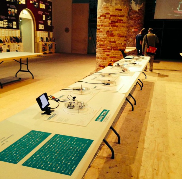
The Arduino space at the Biennale Architettura 2014 has been conceived to inspire visitors to rediscover their ‘maker gene’: the impulse to learn and make things by yourself. Curated by Enrico Bassi, the exhibition includes responsive installations and hands-on demos to encourage visitors to interact and better understand the creative, transformative potential of Arduino and other open-source digital tools.

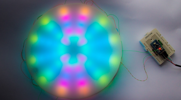
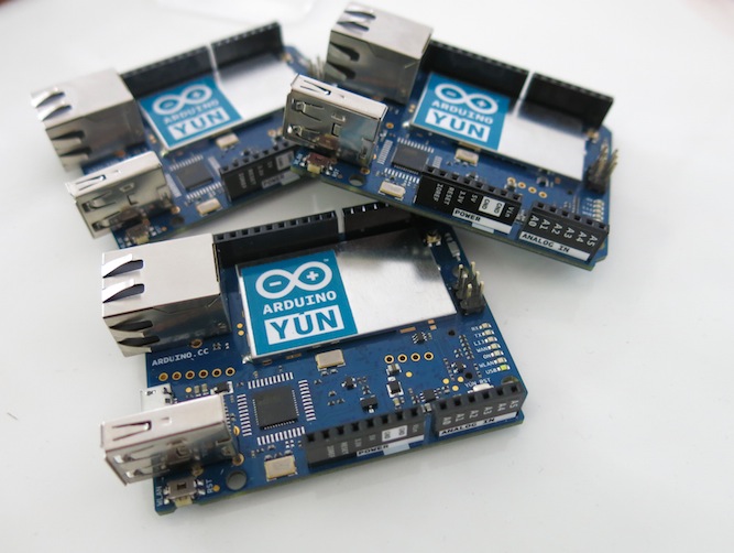
The first section focuses on the history, development and applications of Arduino. It features a glance at the evolution of the board, alongside an illustration of how it can enable an easy, direct approach to electronics and programming. In a dedicated area, the Treviso Arduino User Group, a local community of makers, engages visitors in a two-day hackathon on biometric and environmental sensors. The mezzanine level offers a playful and immersive take on what Arduino can bring to light installations.

A second section explores the impact of Arduino on a variety of innovative projects and businesses. It features a selection of items from Arduino AtHeart, a program designed to support and promote independently developed Arduino-based products: Primo, Smart Citizen Kit, Bare Conductive Touch Board, littleBits Arduino Module, and Cromatica.
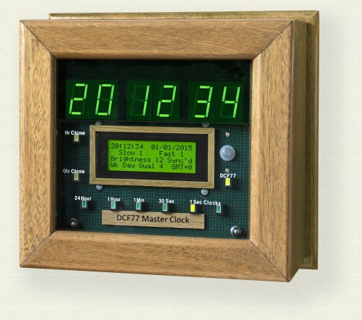
In the Italian Innovators area, a special focus is granted to outstanding examples of how Arduino fosters creativity and technological development in its country of origin: WASProject, a research initiative on architectural 3d-printing; MEG, an innovative open-source home greenhouse; Light Cryptalk, an Arduino-powered recreation of the WW2 Enigma cypher machine.

Ironically extending the maker approach to other, broader parts of society, a set of videos in the final section of the exhibition compares the effects of the closed- and open-source philosophy in sectors ranging from the auto industry to architecture, suggesting the possibility of a radical, pervasive transformation.


The Maker Gene was produced in collaboration with: Fablab Torino, Officine Arduino, Treviso AUG, Torino AUG, MEG, WASProject, Michele Lizzit, Primo, Smart Citizen Kit, Bare Conductive Touch Board, littleBits Arduino Module, and Cromatica.

Supported by: Arduino


Useful links:

Take a look at the general website of La Biennale>>

The venue hosting The Maker Gene is the Arsenale and our installation is hosted within the Weekend Specials initiative.

You can buy your ticket  at this link.
Come and visit us on the 5th and 6th of September from 10am to 8pm!