Simple project, some kind of “Arduino-Wiki” for beginners.

How to do measurements right:
- Biasing AC input using resistor divider and scaling up / down if necessary;
- Sampling fast and accurately using direct access to Control Registers of ADC and Timer1;
- Subtract whatever was added at step #1 from result of Analog / Digital conversion and Square;
- Average / accumulate, filtering following VU specification;
- Sqrt – take square root, Log10 – transform to dB scale;
- Display.
1. Hope, you follow my advice and hack your cheap USB speakers, to get nice ( pre-assembled ! ) analog “front-end” for this project. If not, than get your soldering iron to work, minimum two resistors and 1 cap would required, assuming you already have display wired up and running.
First things with AC measurements ( audio in this category ) on Atmel microcontroler is to get rid of negative half-wave of the input signal, and this what front-end circuitry should do. There are at least two option: rectifying AC to DC before voltage could reach arduino analog input, or biasing signal with external DC offset. Rectification, could nicely be done with help of specifically design IC, LM3914 / 15 / 16 for example. But in this article, I’d describe second alternative, as it’d be not fare to ask you to hack your speakers and than tell you to solder another board…. Here is my set-up, slightly modified version from last blog:
 When AC input signal is mixed with DC offset, so it stays always in positive area, ( think about sine, which defined betseen -1 and +1, if I add +1 it always would be positive ), I only save arduino life, preventing it from destruction by negative voltage. When arduino ADC completes conversion from analog to digital form, I don’t need DC offset anymore, and it should be subtracted.
NOTE: DC voltage was added just to pass audio through arduino ADC.
2. Sampling subroutine is running at 40 kHz, that is more than enough for ANY application. You may decrease sampling rate to lower CPU load, with current settings VU metering consumes more than 50%. Higher sampling rate gives better linearity / precision over wide band, the same time with regular audio content even 10 kHz sampling would provide better than 1 dB accuracy. All input capture process goes in Interruption subroutine, which is configured in setup. Two channels of Timer 1 Configured to run in parallel, “A” is responsible to keep clock at 40 kHz sharp, and “B” fires start conversion event to ADC with the same speed. Restarting new conversion via hardware provides lowest phase noise compare to any other way of doing this.
ADCSRB = ((1<<ADTS2)| // Sets Auto Trigger source – Timer/Counter1 Compare Match B
(0<<ADTS1)|
(1<<ADTS0));
/* Set up TIMER 1 – ADC sampler */
TCCR1A = ((1<<WGM11) | (1<<WGM10)); // Mode 15, Fast PWM
TCCR1B = ((1<<WGM13) | (1<<WGM12)); // Mode 15, Fast PWM
TCCR1B |= (1<<CS10); // clk/1 prescaling.
OCR1A = SMP_TMR1;
OCR1B = SMP_TMR1;
TIFR1 |= (1<<OCF1B);
TIMSK1 |= (1<<OCIE1B);
3 . As you can see in a code snipped below, adc_Offst is subtracted from new ADC result. Quite simple, value of DC offset ( adc_Offst ) was obtained in setup() during start up, using Arduino IDE “analogRead”. The only problem with this simple solution, is that no audio should be present at this moment ( start up ) at input, otherwise all measurements would be erroneous.
ISR(TIMER1_COMPB_vect)
{
int32_t temp = ADC – adc_Offst;
temp = temp * temp;
if ( temp > ppm_Level ) ppm_Level = ((ppm_Level * 255) + temp) >> 8;
else ppm_Level = (ppm_Level * 16383) >> 14;
}
4. The same piece of code includes VU filtering algorithm. I was trying to get as close to standard as possible, but tough timing requirements ( 25 usec ! ) doesn’t allow get full satisfaction. Attack time is very close to specification, 3 milliseconds or so. Decay, I’d estimate in 200 milliseconds, which is less than recommended 650 milliseconds for Peak Program Meter (PPM), and also less than 300 milliseconds for regular VU. The limits come from 32-bit integer math, from one side, and high sampling rate from another.
updated:
This comparison operator if ( temp > ppm_Level ) separates attack – when new value is bigger than stored, and decay – when new value is smaller. Now, lets me explain what this line of code does:
ppm_Level = ((ppm_Level * 255) + temp) >> 8;
Rewriting it to: ppm_Level = ((ppm_Level * 255) + temp) / 256;
and than: ppm_Level = ppm_Level * ( 255 / 256 ) + temp * ( 1 / 256 );
reveals: ppm_Level = ppm_Level * 0.99609375 + temp * 0.00390625;
Which is simple, single pole Low Pass Filter. For more details on recursive filtering I’d refer to this book. Equation 19.2. Trick with right shift operator (>>8) is just to improve speed of calculation. Remind you, that Arduino doesn’t have floating point CPU, and any mathematics work with floating point coefficient very slow.
Same with filtering decay process, the difference is only in coefficient value.
( >> 14) is the same as 1 / 16384, and so 16383 / 16384 = 0.999938965.
5. Read comments, please:
int32_t temp;
temp = ppm_Level; // Take a copy, so Real Value not affected by calculation.
temp = sqrt(temp);
rms_Level = 20.0 * log10(temp +1); // Calculated, available over Serial
6. Last part, drawing VU indicator on graphical display. Ones again, referring you to short hardware description of using model. There is not much to say, all display interface based on GLCD library. The only “tweak” from my side, is that I added “if” condition in front of drawing needle subfunctions:
if ( abs(st1 – st2) > 3 ) // ~1/3 dB
I discovered, that DrawLine is quite slow, 4 calls ( 2 – erase, 2 – draw, all double – to make needle thicker ) take 125 milliseconds, so it make sense not to draw anything if there is not big difference between old and new needle position. At least, new position has to be off by width of the needle itself.
Link to Arduino (UNO) sketch: download.


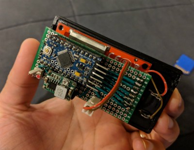
 He writes in to tell us about the handheld device he constructed which lets him view random posts from the popular /r/showerthoughts sub. Each press of the big red button delivers another slice of indispensable Internet wisdom, making it a perfect desk toy to fiddle with when you need a little extra push to get you through the day. Like one of those “Word a Day” calendars, but one that you’ll actually read.


