Pour One Out for This Bottle-Playing Robot

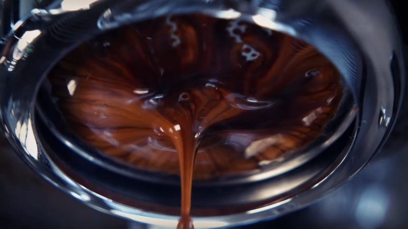
If you have an iota of musicality, you’ve no doubt noticed that you can play music using glass bottles, especially if you have several of different sizes and fill them with varying levels of water. But what if you wanted to accompany yourself on the bottles? Well, then you’d need to build a bottle-playing robot.
 First, [Jens Maker Adventures] wrote a song and condensed it down to eight notes. With a whole lot of tinkling with a butter knife against their collection of wine and other bottles, [Jens] was able to figure out the lowest note for a given bottle by filing it with water, and the highest note by emptying it out.
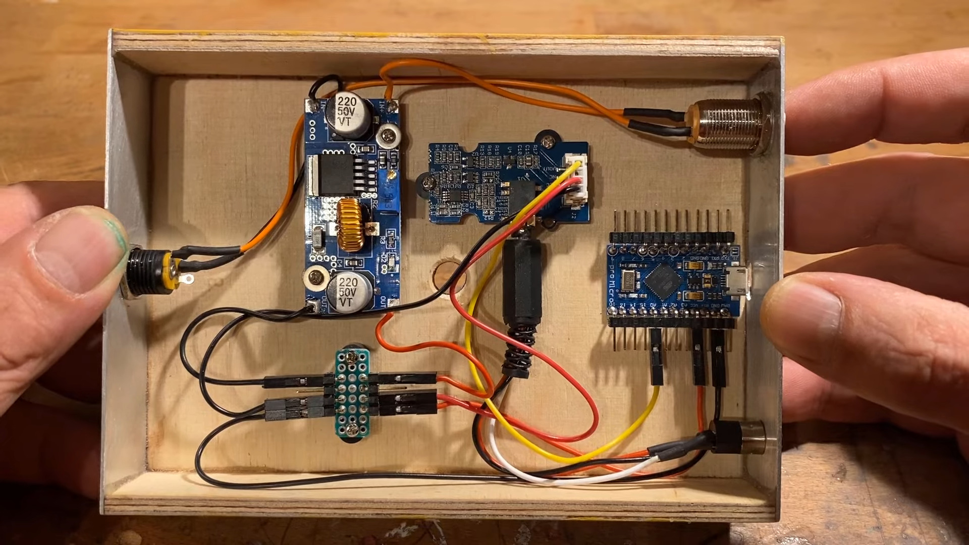
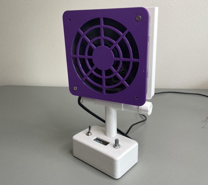
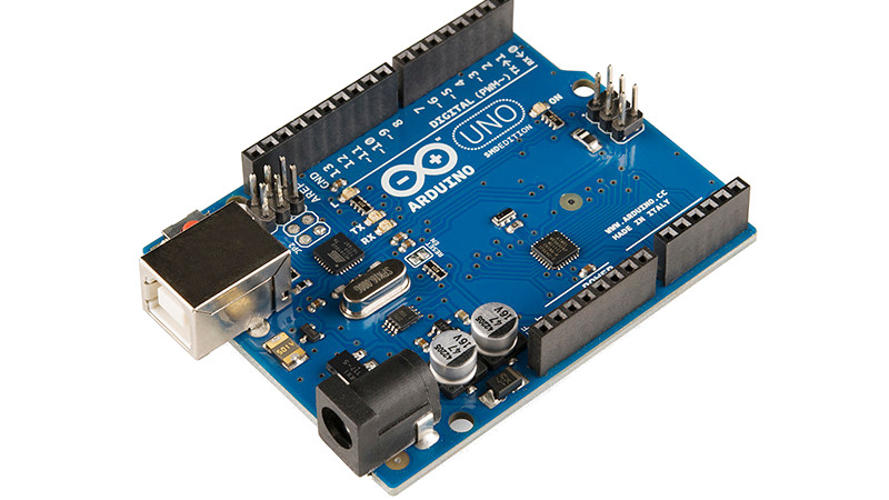
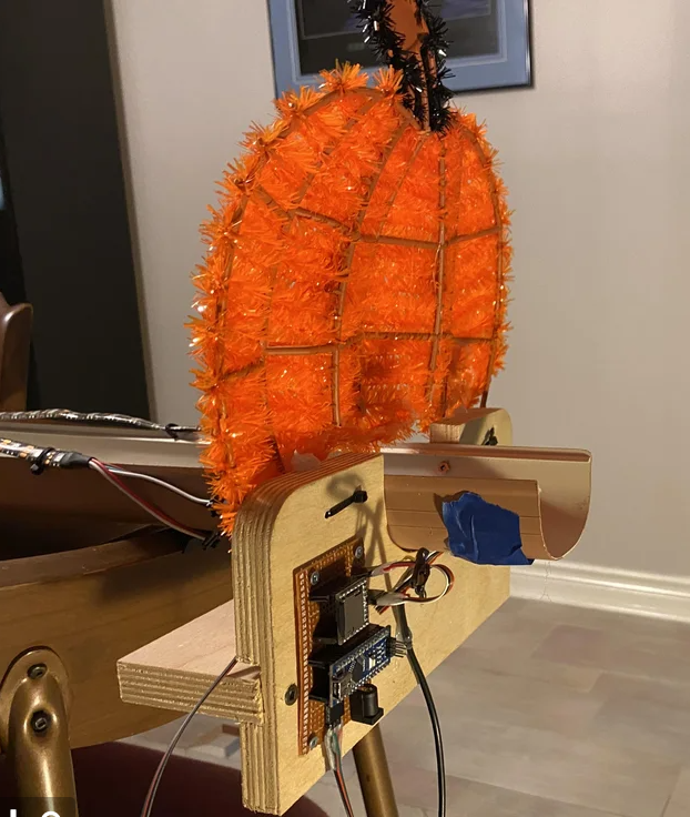
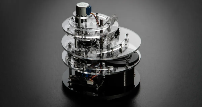
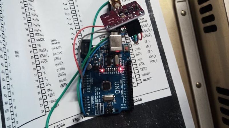
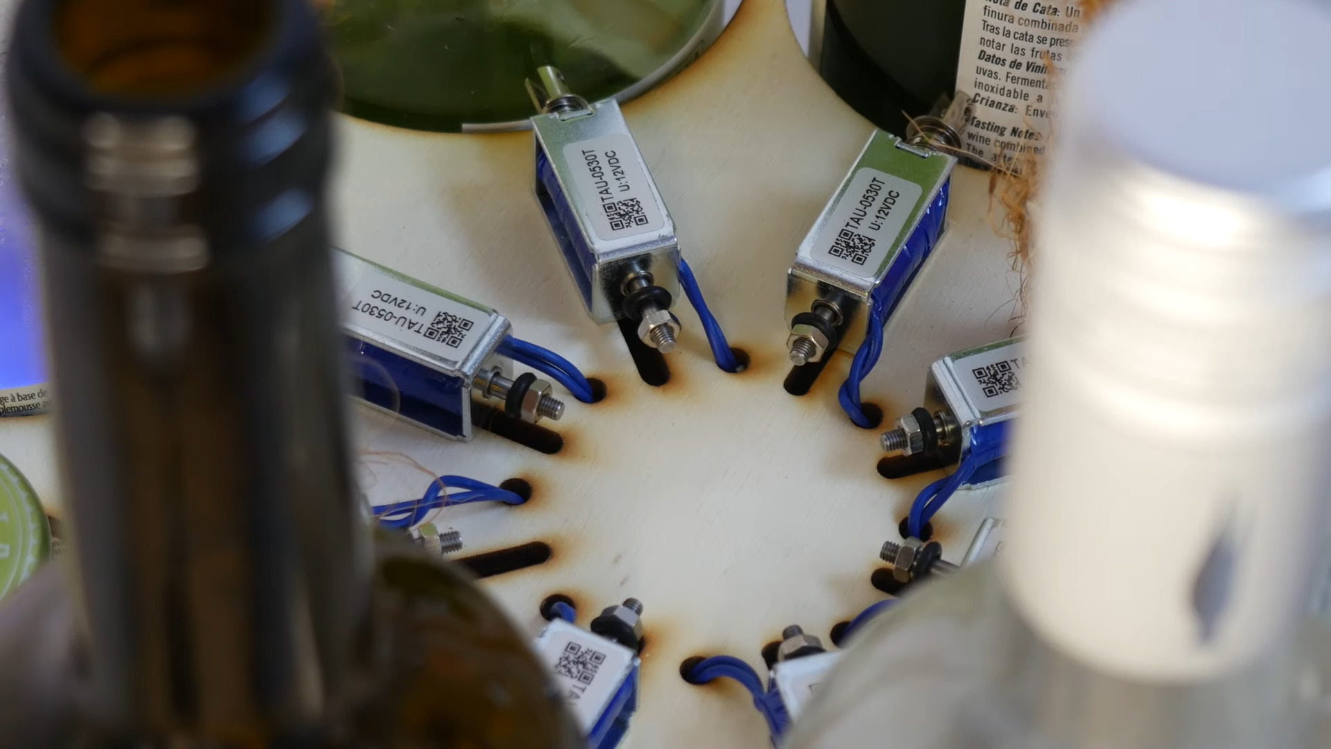
With the bottle notes selected, the original plan was to strike the bottles with sticks. As it turned out, 9g servos weren’t up to the task, so he went with solenoids instead. Using Boxes.py, he was able to parameterize a just-right bottle holder to allow for arranging the bottles in a circle and striking them from the inside, all while hiding the Arduino and the solenoid driver board. Be sure to check it out after the break.
Don’t have a bunch of bottles lying around? You can use an Arduino to play the glasses.