Posts with «usb c» label

A Mega-Tiny Arduino

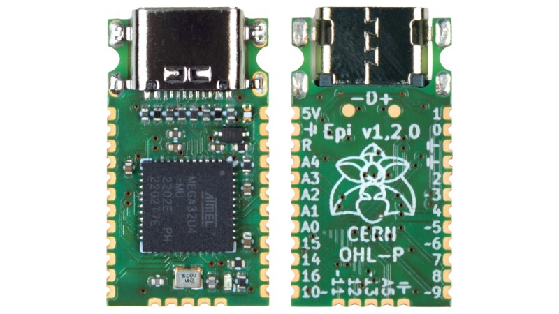
Integrated circuits, chipsets, memory modules, and all kinds of other transistor-based technology continues to get smaller, cheaper, and more energy efficient as time moves on. Not only are the components themselves smaller, but their supporting infrastructure is as well. Computers like the Raspberry Pi are about the size of a credit card and have computing power on the order of full-sized PCs from a few decades ago. The Arduino is no exception to this trend, either, and this new dev board called the Epi 32U4 might be the smallest ATmega platform we’ve seen so far.

As the name suggests, the board is based around the ATmega32U4 which is somewhat unique among Atmel chips in that it includes support for USB within the chip itself rather than relying on external translating circuitry. This makes it an excellent choice for any project which involves sending keyboard, mouse, or other peripheral information to a computer. This goes a few steps further with eliminating “bloat” compared to other boards, too. There’s no on-board voltage regulator, no LEDs except for a single one on pin 13, and even the pins and screw terminals are hemispherical rather than through-hole to save space.

One of the other features this board boasts over other small form factor boards is on-board USB-C, which is definitely a perk as more and more devices switch away from the various forms of older USB-type plugs. The project’s specifications are also available on this GitHub page for anyone that wants to produce their own. And, if you don’t have a 32U4 on hand and still want to build a keyboard project, it’s possible to get some other Arduinos to support these features but it’ll take a little more work.

Thanks to [Rasmus L] for the tip!

Hack a Day 03 Mar 00:00

Portrait of a Digital Weapon

Over the years, artists have been creating art depicting weapons of mass destruction, war and human conflict. But the weapons of war, and the theatres of operation are changing in the 21st century. The outcome of many future conflicts will surely depend on digital warriors, huddled over their computer screens, punching on their keyboards and maneuvering joysticks, or using devious methods to infect computers to disable or destroy infrastructure. How does an artist give physical form to an unseen, virtual digital weapon? That is the question which inspired [Mac Pierce] to create his latest Portrait of a Digital Weapon.

[Mac]’s art piece is a physical depiction of a virtual digital weapon, a nation-state cyber attack. When activated, this piece displays the full code of the Stuxnet virus, a worm that partially disabled Iran’s nuclear fuel production facility at Natanz around 2008.

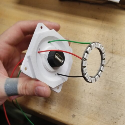
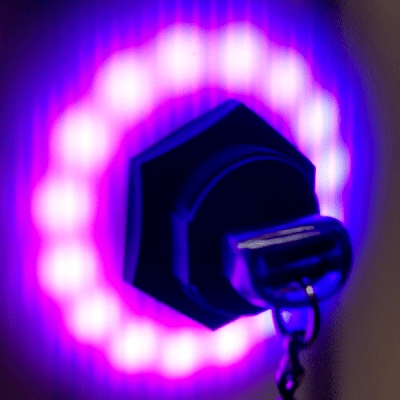
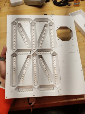
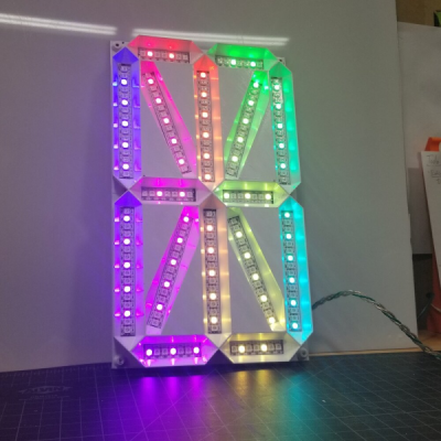
It took a while for [Mac] to finalize the plan for his design. He obtained a high resolution satellite image of the Iranian Natanz facility via the Sentinel Hub satellite imagery service. This was printed on a transparent vinyl and glued to a translucent poly-carbonate sheet. Behind the poly-carbonate layer, he built a large, single digit 16-segment display using WS2812 addressable LED strips, which would be used to display the Stuxnet code. A bulkhead USB socket was added over the centrifuge facility, with a ring of WS2812 LEDs surrounding the main complex. When a USB stick is plugged in, the Stuxnet code is displayed on the 16-segment display, one character at a time. At random intervals, the LED ring around the centrifuge building lights up spinning in a red color to indicate centrifuge failure.

The 16-segment display was built on an aluminum base plate, with 3D printed baffles to hold the LED strips. To hold the rest of the electronics, he built a separate 3D printed frame which could be added to the main art frame. Since this was too large to be printed in one piece on the 3D printer, it was split in parts, which were then joined together using embedded metal stud reinforcement to hold the parts together. Quite a nice trick to make large, rigid parts.
An Adafruit Feather M0 micro-controller board, with micro SD-card slot was the brains of the project. To derive the 5 V logic data signal from the 3.3 V GPIO output of the Feather, [Mac] used two extra WS2812 LEDs as level shifters before sending the data to the LED strips. Driving all the LEDs required almost 20 W, so he powered it using USB-C, adding a power delivery negotiation board to derive the required juice.

The Arduino code is straightforward. It reads the characters stored on the SD-card, and sends them sequentially to the 16-segment display. The circular ring around the USB bulkhead also lights up white, but at random intervals it turns red to simulate the speeding up of the centrifuges. Detecting when the USB stick gets plugged in is another nice hack that [Mac] figured out. When a USB stick is plugged in, the continuity between the shell (shield) and the GND terminal was used to trigger a GPIO input.

Cyber warfare is here to stay. We are already seeing increasing attacks on key infrastructure installations by state as well as non-state actors around the world. Stuxnet was one of the first in this growing category of malicious, weaponized code. Acknowledging its presence using such a physical representation can offer a reminder on how a few lines of software can wreak havoc just as much as any other physical weapon. Check out the brief project video after the break.
USB-C Programmable Power Supply For Any Project

USB-C Power Delivery 3.0 (PD3.0) introduces a new Programmable Power Supply (PPS) mode, which allows a device to negotiate any supply of 3.3-21 V in 20 mV steps, and up to 5 A of current in 50 mA steps. To make use of this new standard, [Ryan Ma] create the PD Micro, an Arduino-compatible development board, and a self-contained software library to allow easy integration of PD3.0 and the older PD2.0 into projects.

The dev board is built around an ATMega32U4 microcontroller and FUSB302 USB-C PHY. The four-layer PCB is densely packed on both sides to fit in the Arduino Pro Micro Form factor. The board can deliver up to 100W (20 V at 5 A) from an appropriate power source and shows visual feedback on the PD status through a set of LEDs.

The primary goal of the project is actually in the software. [Ryan] found that existing software libraries for PD take up a lot of memory, and are difficult to integrate into small projects. Working from the PD specifications and PD PHY chip data sheet, he created a lighter weight and self-contained software library which consumes less than 8 K of flash and 1 K of RAM. This is less than half the Flash and RAM available on the ATmega32U4.

[Ryan] is running a Crowd Supply campaign (video after the break) to get some of these powerful boards out in the wild, and has released all the source code and schematics on GitHub. The PCB design files will be released during the last week of the campaign, around 25 January 2021.

USB-C and power delivery are not simple standards, but the ability to add a high-speed data interface and a programmable power supply into almost any project has real potential.

An Arduino Pro Micro With USB-C

USB-C versus USB Micro connectors are turning into one of the holy wars of our time. Rather than be left on the wrong side of the divide [Stefan S] has come up with his own USB-C version of of an Arduino Pro Micro to avoid having to always find a different cable.

Home made Arduinos come in all shapes and sizes from the conventional to the adventurous, and from the pictures it seems that this one is firmly in the former camp. The USB-C is present in connector form alone as the device is only capable of talking at the much slower speed of the ATMEGA32U4 processor, but having the newer connector should at least make cabling more accessible.

This is one of the most practical Arduino clones we’ve ever seen, but one of our other favourites is also a bit impractical.

Look what came out of my USB charger !

Quick Charge, Qualcomm’s power delivery over USB technology, was introduced in 2013 and has evolved over several versions offering increasing levels of power transfer. The current version — QCv3.0 — offers 18 W power at voltage levels between 3.6 V to 20 V.  Moreover, connected devices can negotiate and request any voltage between these two limits in 200 mV steps. After some tinkering, [Vincent Deconinck] succeeded in turning a Quick Charge 3.0 charger into a variable voltage power supply.

His blog post is a great introduction and walk through of the Quick Charge ecosystem. [Vincent] was motivated after reading about [Septillion] and [Hugatry]’s work on coaxing a QCv2.0 charger into a variable voltage source which could output either 5 V, 9 V or 12 V. He built upon their work and added QCv3.0 features to create a new QC3Control library.

To come to grips with what happens under the hood, he first obtained several QC2 and QC3 chargers, hooked them up to an Arduino, and ran the QC2Control library to see how they respond. There were some unexpected results; every time a 5 V handshake request was exchanged during QC mode, the chargers reset, their outputs dropped to 0 V and then settled back to a fixed 5 V output. After that, a fresh handshake was needed to revert to QC mode. Digging deeper, he learned that the Quick Charge system relies on specific control voltages being detected on the D+ and D- terminals of the USB port to determine mode and output voltage. These control voltages are generated using resistor networks connected to the microcontroller GPIO pins. After building a fresh resistor network designed to more closely produce the recommended control voltages, and then optimizing it further to use just two micro-controller pins, he was able to get it to work as expected. Armed with all of this information, he then proceeded to design the QC3Control library, available for download on GitHub.

Thanks to his new library and a dual output QC3 charger, he was able to generate the Jolly Wrencher on his Rigol, by getting the Arduino to quickly make voltage change requests.


Filed under: Arduino Hacks, hardware