Posts with «low power» label

Off-Grid Radio Also Repairable Off-Grid

Low-power radios, often referred to in the amateur radio community as QRP radios, have experienced a resurgence in popularity lately. Blame it on certain parts of the hobby become more popular, like Parks on the Air (POTA) or Summits on the Air (SOTA). These are events where a radio operator operates off-grid at remote parks or mountaintops. These QRP rigs are a practical and portable way to make contacts. You would think that a five- or ten-watt rig running on batteries would be simple. Surprisingly, they can be enormously complex and expensive. That’s why [Stephen] built the RFBitBanger, a QRP radio designed to not only be usable off-grid but to be built and maintained off-grid as well.

The radio accomplishes this goal by being built out of as many standard off-the-shelf components as possible. It eschews modern surface-mount components in favor of the much more accessible through-hole parts, including the ATMEGA328P at the center of the build. A PCB design is also available, but it can be built on perf board nearly as easily. The radio supports any mode a QRP operator might use, including CW, SSB, RTTY, and a new mode designed explicitly for this radio called SCAMP which is a low bandwidth, low SNR digital mode built into the Arduino-based firmware. It’s a single-band radio, but any band between 20 and 80 meters can be selected with pluggable filters.

As far as bomb-proof radios go, we can’t imagine a better way to live out an apocalypse than with a radio like this. As long as there’s a well-stocked parts drawer around, this radio could theoretically reach around the world without worrying about warranty claims, expensive parts, or even a company going out of business or not stocking parts for old radios anymore. There’s also more information about this build at the Open Research Institute for those interested. And, if you’re wondering how useful any radio could be using only five watts of transmitter power, take a look at this in-depth look at QRP radio operation.

An Ultra Low Power Dash Cam

Dash cameras are handy as they provide a video recording of interactions on the road. However, their utility comes from the fact that they are always recording while driving. This always-on means power draw. [Kuzysk] took it upon himself to cut that power draw by a factor of almost 70x.

He found his existing dash cam from MiVue consumed 3.5mA in idle which works out to be a whole amp-hour every 12 days. The custom version takes just 50uA which means it will draw an amp-hour in two years. The brains of the chip are formed by an ATmega328 and an LM2596M, which is a simple step-down regulator. Interestingly, [Kuzysk] purchased clones and original chips and found that the cheaper clones had a lower switching frequency but a much lower power draw. Programming an Arduino bootloader onto the board is fairly straightforward and [Kuzysk] kindly provides his code. It can detect the ACC voltage that’s on when the engine is on and is powered by a permanent 12v connection to the battery.

Overall it’s a straightforward hack that goes through rolling your own Arduino, optimizing for low power, and putting it all together into a polished project. Perhaps for the next version, he can use the ATmega to control a cheaper camera and make it smart.

Thanks to [Microchip makes] and [Abe] for the tip!

Underwater Logging for Science

Logging data with an Arduino is old-hat for most Hackaday readers. However, [Patricia Beddows] and [Edward Mallon] had some pretty daunting requirements. Their sensors were going underground and underwater as part of an effort to study conditions underwater and in caves. They needed to be accessible, yet rugged. They didn’t want to use batteries that would be difficult to take on airplanes, but also wanted more than a year of run time. You can buy all that, of course, if you are willing to pay the price.

Instead, they used off-the-shelf Arduino boards connected together inside PVC housings. Three alkaline AA batteries are compact and give them more than a year of run time. They wrote a journal paper to help other scientists use the same techniques for the Sensors journal published by the Multidisciplinary Digital Publishing Institute.

If you regularly read Hackaday, you probably won’t find the electronic part of the build remarkable. However, that’s kind of the point, as this is all off-the-shelf and inexpensive. They do however modify the boards in some cases to allow the controller to power them down, for example.

In fact, they put a lot of thought into reducing power requirements. Since your eye is more sensitive to green, for example, they use green LEDs with very low currents as indicators. They also speed up the serial bus going to sensors because they found that the increased power required was more than offset by finishing the transaction faster (and, thus, going back to sleep sooner).

The PVC enclosures are also interesting. The paper shows some practical deployments in some very harsh conditions. If you want more practical details, the Cave Pearl project has been blogging about their development of these loggers for a while. They have a good “how to” page, as well.

If an Arduino seems too last-year for you, we’ve seen long-duration logging done with ESP8266s and ESP32s. However, they did use lithium-ion cells. Spoiler alert: The ESP8266 lasts longer than the ESP32. If you want to minimize power when sending things out over a network connection, consider MQTT.

Remember Your Birthday For Fifty Years

Our Coin Cell Challenge competition has turned up some amazing entries, things that we wouldn’t have thought possible from such meagre power sources. Take [Vishnu M Aiea]’s entry for instance, a device which he claims can light up as a birthday reminder every year for up to fifty years.

At its heart is a modified Arduino Nano clone that draws a measured 608 nA from a CR2450N. From the specification of the cell he has calculated the 50 year maximum figure, as well as a possible 29 years for a CR2032 and 64 years for a CR2477. He does however note that this does not take self-discharge into account, but you can probably afford a new battery in a decade or so.

The Arduino clone carefully selected for its “P” version low-power processor has had its serial bridge IC removed to achieve this power consumption, as well as a voltage regulator and some discrete components. Interestingly he notes that the ATMega168P is even more frugal than its 328 cousin, so he’s used the former chip. A selection of internal flags are set for minimal power consumption, and the internal oscillator is selected to use as low a clock speed as possible. There is an Intersil ISL1208 low power RTC chip mounted on a piece of stripboard to provide the timing, and of course an LED to provide the essential birthday alert.

When the LED lights for the big day there’s always the hope you’ll receive another coin cell, this time powering an edge-lit musical birthday card.


It Keeps on Going and… Arduino Edition

How long can you keep an Arduino circuit running on three AA batteries? With careful design, [educ8s] built a temperature sensor that lasts well over a year on a single charge of three 2250 mAH rechargeable cells (or, at least, should last that long).

Like most long-life designs, this temperature sensor spends most of its time sleeping. The design uses a DS18B20 temperature sensor and a Nokia 5110 LCD display. It also uses a photoresistor to shut off the LCD display in the dark for further power savings.

During sleep, the device only draws 260 microamps with the display on and 70 microamps with the display off. Every two minutes, the processor wakes up and reads the temperature, drawing about 12 milliamps for a very short time.

Along with the code, [educ8s] has a spreadsheet that computes the battery life based on the different measured parameters and the battery vendor’s claimed self discharge rate.

Of course, with a bigger battery pack, you could get even more service from a charge. If you need a refresher on battery selection, we covered that not long ago. Or you can check out a ridiculously complete battery comparison site if you want to improve your battery selection.


Filed under: Arduino Hacks

Low-power remote power-independent (solar charged) sensor node!

Well, for a while now I've been entertaining the idea of building a remote sensor node to keep track/record of my indoors "balcony orchard".

This project here will be my starting point, a Low-Power Wireless Sensor Node where most of the work is already cut out for me.

It's power consumptions are reported to be:

Sleep Consumption 0.14 mA

read more

Let's Make Robots 03 Mar 16:58

Making the Arduino sleep the long sleep

Earlier this week, I showed you [Naim Busek's] kickstarter for his turn signal helmet. In that article I explained that, while the helmet is a neat idea, I was really interested in what [Naim] had told me about his power consumption.  To put it the shortest way, he has made his arduino sleep so efficiently, it can be waiting for input longer than the battery’s optimum shelf life.

After that article, [Naim] wrote in to give me the details on what he did to achieve such an efficient system. You can read his entire explanation, un altered here.


Have been searching off and on for a particular app note that I wanted to share with you but could not for the life of me find it. Seeing your post I bit the bullet and spent the last few hours searching and finally located it. The document is Designing With Logic from Texas Instruments. The interesting part is Figure 5 (will explain why a little later).

A dive into the low power operation of Arduino hardware

Started with the basics. Made sure all LED driver pins were in the off state by default. The removed the load resistors for all of the feedback LEDS I could not switch off like the one connected to VCC that wastes power any time the battery is connected. As an implementation note, I actually turned SMT resistor sideways and left them connected by one pad. Makes it easy to reinstall it if I want them later.

I had planned to not use the onboard voltage regulator from the beginning because the quiessent current it use is huge 100+ uA. The shield I designed and built used a lower current (50mA vs. 250mA) regulator since I was planning to use it only for the control electronics and sensors. The high current LEDs would run directly off of the higher voltage without any regulation. Since the micro and sensors draw 12-15mA max when fully on 50mA was way more than enough.

The expected current draw for my system was:

  • Voltage regulator: ~5-6uA
  • ATMega328p: ~1uA
  • CMA3000 (@10Hz w/ wakeup): ~10uA

Total: ~16uA

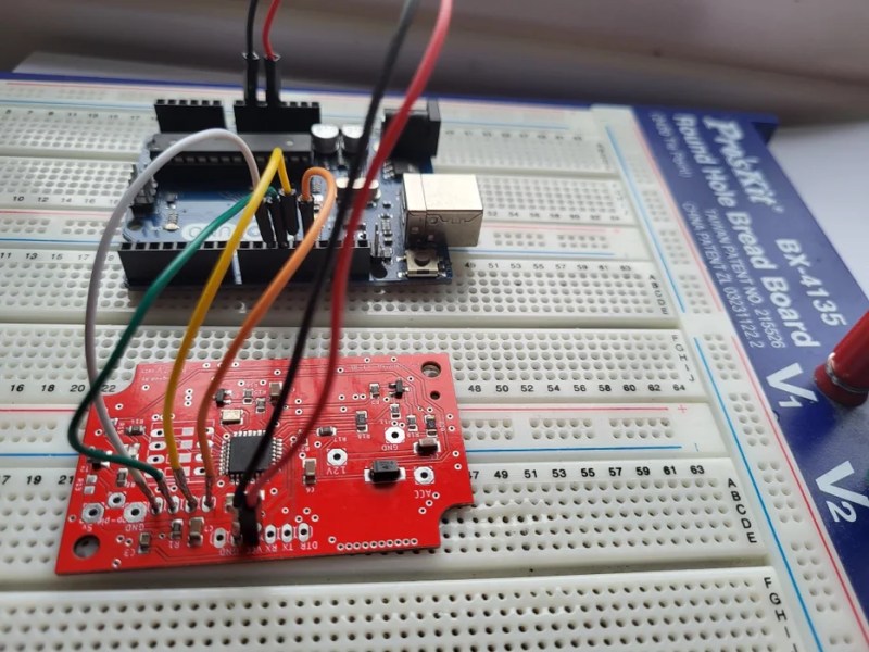
Note: The testing below was done on both an Arduino Pro Mini and an Arduino Fio with similar results. The bike helmet prototype was built on top of an Arduino Fio.

To get the device into low power I started with the Arduino example sleep sketch and went through the guidelines from the datasheet to try and figure out why it was drawing so much power. The Arduino was using ~420uA when the chip is while the data sheet claims

Knowing that I went ahead and bypassed disconnected the supply from Arduino battery input, connected it to the input of my ultra low quiescent voltage regulator and connected the output of that directly to the Arduino VCC. Current system draw went UP to ~155uA. WTF???

Next thing I looked for was pullups on the digital lines for I2C and/or SPI. Not just pins configured as outputs and driven the wrong way but also looking at what weak pullups were intentionally (or accidentally) enabled. I have seen this catch out a number of Arduino developers. If the output value of a pin is configured high, when it is switched to being an input it does not just switch to being a high impedance input. If the digital output register is set a weak pullup (for the AVR Rpu = 20-50kOhms) is enabled on that pin. If a peripheral then decides to make that signal on that input low, the system suddenly sees an increase of VCC/Rpu of current that would not be there if the pullup were not enabled. Whenever I see a system that is some weird multiple of VCC/Rpu off of where it’s sleep current is supposed to be I will look for an input pullup that should not be enabled. In this case with a 3.3V rail a pullup would cause 60-150uA draw. Reviewed all of my code, probed the pins and did not find anything configured wrong. Happy that I didn’t screw anything up but unhappy that i Still have 140uA (of 150uA) disappearing into the ether and sucking my battery dry.

Then I started looking for some of the more obscure types of failures that could be causing this. One of those things that I discovered (then had a crash course on how to fix) is something call “back-powering of digital output pins” or sometimes “pin powering” or “port powering” of a device. Now back to Designing With Logic. Looking at Figure 5, if a chip that has digital I/O is powered down (VCC disconnected) then voltage is applied externally to that I/O that voltage can cause D1 on the input or D3 on the output to reverse bias, allow current to flow and feed the internal VCC of the chip with that voltage (minus a diode drop). Then really weird things can start happening. Most current digital chips can easily run at 1.8V (0.9V for some of the newer ones) so if a an external pin is driven at 3.3V and enough current can sneak through the diode, the part will happily keep running on the 2.7-3.0V it gets internally. Found this out the hard way with a peripheral that would never shut down and reset. Was right on the edge and drew too much current to startup by back powering but once running would happily keep running by back powering. Gave it 3.3V and it turned on took it away and it just kept on running. Was super confusing, since could turn it on but not off???

While the output of the regulator is not a digital I/O pin I got to thinking that something might still be going on with the output circuitry. So I cut the output trace from the regulator on the Fio (I just removed the regulator completely from the Pro Mini) and the current draw dropped to 34uA. This gave me a more than 10x decrease in sleep current for a 10x battery life increase. Running off of 1900mAHr AA batteries it should sleep, still doing 10Hz sampling to detect motion, for 6-7 years. With the 9V batteries in my prototype at 590mAHr it is just shy of two years.

At this point I moved forward with the kickstarter comfortable that I could hit the lifetime targets I had set. The current was still about double my back of the envelope calculations but was not going to be a showstopper. It was still weighing on me that there was something in the system that I did not know exactly how and why it was happening. Just yesterday when I was thinking about this again, I found the spark fun tutorial Adventures in Low Power Land. While I had independently done the same initial steps while going through this process I did not get to the point of looking at the brown out detection (BOD) and changing the fuses. Given that the BOD consumes 15-20uA I am now very happy with my 34uA sleep meaning that with BOD disabled I should be at 14-19uA. :) For 1900mAHr battery that gives a 10-12 year sleep time. That is well beyond the 5-7 year shelf life of a normal alkaline battery. Any time I am exceeding the storage the storage life and approaching the self depletion time of the battery I am very happy. :)


Filed under: arduino hacks, HackIt
Hack a Day 18 Aug 17:01

Attiny-Duino or whatever?

Hi geeks ;-)

I am thinking about to shrink some of my projects. That's the deal. I am planning to build a Attiny-Duino.

What would you think about it's usage? For myself I would use it in the Insect bot to reduce the weight, costs and power comsumption.