This Arduino Debugger Uses the CH552
One of the things missing from the “classic” Arduino experience is debugging. That’s a shame, too, because the chips used have that capability. However, the latest IDE has the ability to work with external debuggers and if you want to get started with a classic ATMega Arduino, [deqing] shows you how to get started with a cheap CH552 8-bit USB microcontroller board as the debugging dongle.
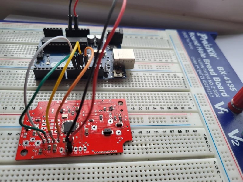
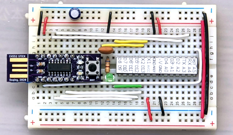
The CH552 board in question is a good choice, primarily because it is dirt cheap. There are design files on GitHub (and the firmware), but you could probably pull the same trick with any of the available CH552 breakout boards.
There was a time when having a god-eye view of your embedded system required an expensive in-circuit emulation system. These were expensive, difficult to deploy, and rare. Then, CPUs started adding debugging hardware right on the chip. A few spare pins on the CPU and some sort of adapter would give you most of what you wanted from an emulation system. Although these adapters are often proprietary, sometimes they aren’t, or they have been reverse-engineered. If you know the protocol, it is easy enough to get a processor to speak it for you. That’s why you often see, for example, Raspberry Pi Picos debugging other Picos. There’s nothing you can’t do a million other ways here, but it is an excellent step-by-step tutorial for getting started without breaking the bank.