Posts with «arduino hacks» label

IR Remote Tester Helps You Crack the Code

Even though some devices now use WiFi and Bluetooth, so much of our home entertainment equipment still relies on its own proprietary infrared remote control. By and large (when you can find them) they work fine, but what happens when they stop working?  First port of call is to change the batteries, of course, but once you’ve tried that what do you do next? [Hulk] has your back with this simple but effective IR Remote Tester / Decoder.

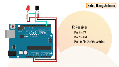
How to connect the TSOP4838 to an Arduino to read the transmitted codes

By using a cheap integrated IR receiver/decoder device (the venerable TSOP4838), most of the hard work is done for you! For a quick visual check that your remote is sending codes, it can easily drive a visible LED with just a resistor for a current-limit, and a capacitor to make the flickering easier to see.

For an encore, [Hulk] shows how to connect this up to an Arduino and how to use the “IRremote” library to see the actual data being transmitted when the buttons are pressed.

It’s not much of a leap to imagine what else you might be able to do with this information once you’ve received it – controlling your own projects, cloning the IR remote codes, automating remote control sequences etc..

It’s a great way to make the invisible visible and add some helpful debug information into the mix.

We recently covered a more complex IR cloner, and if you need  to put together a truly universal remote control, then this project may be just what you need.

The Great Resistor Embiggens the Smallest Value

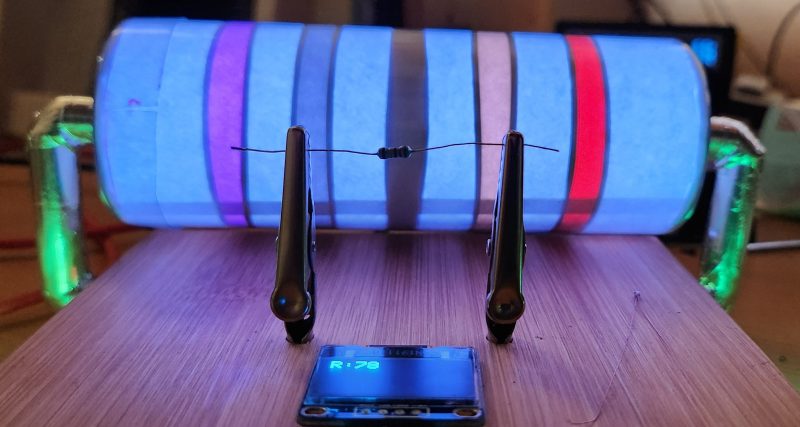
With surface-mount components quickly becoming the norm, even for homebrew hardware, the resistor color-code can sometimes feel a bit old-hat. However, anybody who has ever tried to identify a random through-hole resistor from a pile of assorted values will know that it’s still a handy skill to have up your sleeve. With this in mind, [j] decided to super-size the color-code with “The Great Resistor”.

How the resistor color-code bands work

At the heart of the project is an Arduino Nano clone and a potential divider that measures the resistance of the test resistor against a known fixed value. Using the 16-bit ADC, the range of measurable values is theoretically 0 Ω to 15 MΩ, but there are some remaining issues with electrical noise that currently limit the practical range to between 100 Ω and 2 MΩ.

[j] is measuring the supply voltage to help counteract the noise, but intends to move to an oversampling/averaging method to improve the results in the next iteration.

The measured value is shown on the OLED display at the front, and in resistor color-code on an enormous symbolic resistor lit by WS2812 RGB LEDs behind.

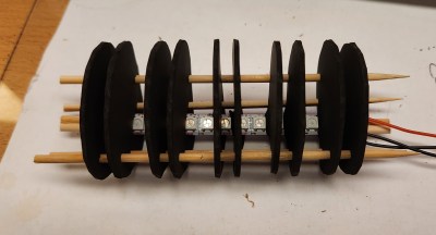
Inside The Great Resistor, the LEDs and baffle plates make the magic work

Precision aside, the project looks very impressive and we like the way the giant resistor has been constructed. It would look great at a science show or a demonstration. We’re sure that the noise issues can be ironed out, and we’d encourage any readers with experience in this area to offer [j] some tips in the comments below. There’s a video after the break of The Great Resistor being put through its paces!

If you want to know more about the history of the resistor color code bands, then we have you covered.  Alternatively, how about reading the color code directly with computer vision?

Walnut Case Sets This Custom Arduino-Powered RPN Calculator Apart from the Crowd

How many of us have an everyday tool that’s truly unique? Likely not many of us; take a look around your desk and turn out your pockets, but more often than not, what you’ll find is that everything you have is something that pretty much everyone else on the planet could have bought too. But not so if you’ve got this beautiful custom RPN calculator in a wooden case.

This one comes to us from [Shinsaku Hiura], who generally dazzles us with unique mechanical clocks and displays. This calculator solves a more practical problem — the dearth of RPN calculators on the market with the correct keyboard feel, specifically with the large keys and light touch he desired. Appropriately, the build started with a numeric keypad, which once liberated of its USB interface was reverse-engineered to figure out how the matrix was wired. Next up, a custom PCB to connect the keypad to an Arduino and a 20×4 LCD display was milled up, while a test case was designed and printed to check fitment. The final case was milled from a block of solid walnut and fitted with an acrylic window, for a sharp look with clean lines and pleasing colors.

As for the calculator itself, the demo below shows it going through its paces. The code is clever because it leverages the minimal number of keys available by hiding all the scientific and engineering functions behind a “secret silver key” that was once the equals key and obviously not needed in RPN. Hats off to [Shinsaku] for a handsome and unique addition to his desk.

One Of The Worst Keyboards Ever, Now An Arduino Peripheral

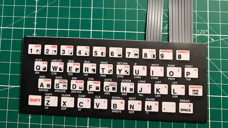
For British kids of a certain age, their first experience of a computer was very likely to have been in front of a Sinclair ZX81. The lesser-known predecessor to the wildly-successful ZX Spectrum, it came in at under £100 and sported a Z80 processor and a whopping 1k of memory. In the long tradition of Sinclair products it had a few compromises to achieve that price point, the most obvious of which was a 40-key membrane keyboard. Those who learned to code on its frustrating lack of tactile feedback may be surprised to see an Arduino project presenting it as the perfect way to easily hook up a keyboard to an Arduino.

Like many retrocomputing parts, the ZX81 ‘board has been re-manufactured, to the joy of many a Sinclair enthusiast. It’s thus readily available and relatively cheap (we think they can be found for less than the stated 20 euros!), so surprisingly it’s a reasonable choice for an Arduino project. The task of trying to define by touch the imperceptible difference in thickness of a ZX81 key will bring a true retrocomputing experience to a new generation. Perhaps if it can be done on an Mbed then someone might even make a ZX81 emulator on the Arduino.

We’re great fans of the ZX81 here at Hackaday, for some of us it was that first computer. Long may it continue to delight its fans!

Plumbing Valves as Heavy Duty Analog Inputs

Input devices that can handle rough and tumble environments aren’t nearly as varied as their more fragile siblings. [Alastair Aitchison] has devised a brilliant way of detecting inputs from plumbing valves that opens up another option. (YouTube) [via Arduino Blog]

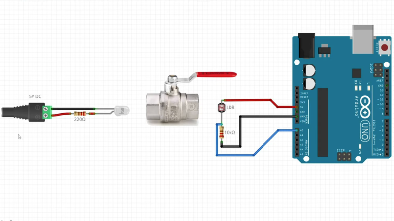
While [Aitchison] could’ve run the plumbing valves with water inside and detected flow, he decided the more elegant solution would be to use photosensors and an LED to simplify the system. This avoids the added cost of a pump and flow sensors as well as the questionable proposition of mixing electronics and water. By analyzing the change in light intensity as the valve closes or opens, you can take input for a range of values or set a threshold for an on/off condition.

[Aitchison] designed these for an escape room, but we can see them being great for museums, amusement parks, or even for (train) simulators. He says one of the main reasons he picked plumbing valves was for their aesthetics. Industrial switches and arcade buttons have their place, but certainly aren’t the best fit in some situations, especially if you’re going for a period feel. Plus, since the sensor itself doesn’t have any moving parts, these analog inputs will be easy to repair should anything happen to the valve itself.

If you’re looking for more unusual inputs, check out the winners of our Odd Inputs and Peculiar Peripherals contest or this typewriter that runs Linux.

DIY Arduino Hearing Test Device

Hearing loss is a common problem for many – especially those who may have attended too many loud concerts in their youth. [mircemk] had recently been for a hearing test, and noticed that the procedure was actually quite straightforward. Armed with this knowledge, he decided to build his own test system and document it for others to use.

Resultant audiogram from the device showing each ear in a different color

By using an Arduino to produce tones of various stepped frequencies, and gradually increasing the volume until the test subject can detect the tone, it is possible to plot an audiogram of hearing threshold sensitivity.  Testing each ear individually allows a comparison between one side and the other.

[mircemk] has built a nice miniature cabinet that holds an 8×8 matrix of WS2812 addressable RGB LEDs.  A 128×64 pixel OLED display provides user instructions, and a rotary encoder with push-button serves as the user input.

Of course, this is not a calibrated professional piece of test equipment, and a lot will depend on the quality of the earpiece used.  However, as a way to check for gross hearing issues, and as an interesting experiment, it holds a lot of promise.

There is even an extension, including a Class D audio amplifier, that allows the use of bone-conduction earpieces to help narrow down the cause of hearing loss further.

There’s some more information on bone conduction here, and we’ve covered an intriguing optical stimulation cochlear implant, too.

Aqua PCB Is a Big Upgrade for the Mattel Aquarius

In case you weren’t around in the 80s, or you happened to blink, you may have missed the Mattel Aquarius computer. [Nick Bild] has a soft spot in his heart for the machine though and built the Aqua cartridge to make the Aquarius into a more usable machine.

Originally equipped with a mere 4 KB of RAM and a small, rubbery keyboard, it’s not too surprising that the Aquarius only lasted five months on the market. [Nick] decided on the cartridge slot to beef up the specs of this little machine given the small number of expansion ports on the device. Adding 32 KB of RAM certainly gives it a boost, and he also designed an SD card interface called Aqua Write that connects to the Aqua cartridge for easily transferring files from a more modern machine.

The Aqua Write uses an Arduino Mega 2560 to handle moving data between the SD card and the system’s memory. This is complicated somewhat because a “PLA sits between the Z80 and data bus that XORs data with a software lock code (initialized to a random value on startup).” [Nick] gets around this by running a small program to overwrite the lock code to zero after startup.

Getting data on and off retrocomputers can certainly be a challenge. If you’re trying to get files on or off another old machine, check out this Simple Universal Modem or consider Using a Raspberry Pi as a Virtual Floppy Drive.

Lo-Fi Orchestra Learns Tubular Bells

Hardware projects often fall into three categories: Those that flash lights, those that make sounds and those that move. This virtuoso performance by [Kevin]’s “Lo-Fi Orchestra” manages all three, whilst doing an excellent job of reproducing the 1973 musical classic Tubular Bells by Mike Oldfield.

Producing decent polyphonic sounds of different timbres simultaneously is a challenge for simple microcontroller boards like Arduinos, so [Kevin] has embraced the “More is more” philosophy and split up the job of sound generation in much the same way as a traditional orchestra might. Altogether, 11 Arduino Nanos, 6 Arduino Unos, an Arduino Pro Mini, an Adafruit Feather 32u4, and a Raspberry Pi running MT32-Pi make up this electronic ensemble.

Arduino Servo & Relay Drumkit

The servo & relay drumkit is a particular highlight, providing some physical sounds to go along with the otherwise solid-state generation.

The whole project is “conducted” over MIDI and the flashing sequencer in the middle gives a visual indication of the music that is almost hypnotic. The performance is split into two videos (after the break), and will be familiar to fans of 70’s music and classic horror movies alike. We’re astonished how accurately [Kevin] has captured the mood of the original recording.

If this all looks slightly familiar, it may be because we have covered the Lo-Fi Orchestra before, when it entertained us with a rousing rendition of Gustav Holst’s Planets Suite. If you’re more interested in real Tubular Bells than synthesized ones, then check out this MIDI-controlled set from 2013.

Tiny Thin Client is Small But Compatible

We were impressed with [moononournation’s] tiny thin client project. It claims to use an Arduino, but as you might guess it is using the Arduino software along with a network-enabled microcontroller like an ESP32. The impressive part is that it is standards-compliant and implements VNC’s RFB protocol.

The original coding for RFB on Arduino is from [Links2004] and armed with that, the thin client is probably easier to create than you would guess. However, this project wanted to use a larger screen and found that it led to certain problems. In particular, the original code had a 320×240 display. This project was to use an 800×480 display, but with the limits on the ESP32, the frame rate possible would be under 7 frames per second. The answer was to combine a 16-bit parallel interface with better compression back to the VNC server.

The little keyboard is probably not very practical, but it is compact. That would be another easy thing to modify. Currently, the keyboard uses I2C, but it would be straightforward to change things up. This would be a worthy base to build a bigger project on top. A 3D printed enclosure would be nice, too.

We’ve seen a number of projects built around commercial thin clients. Some from defunct businesses are good sources for obscure parts, too.

Simple CNC Gear Production with Arduino

We’ve seen plenty of people 3D printing custom gears over the years, but [Mr Innovative] decided against an additive process for his bespoke component. He ended up using a simple CNC machine that makes use of several components that were either salvaged from a 3D printer or produced on one. Using a small saw blade, the machine cuts gear teeth into some plastic material and — presumably — could cut gears into anything the saw blade was able to slice into, especially if you added a little lubrication, cooling, and dust removal.

If you’ve built a 3D printer, you’ll see a lot of familiar parts. Stepper motors, aluminum extrusion, straight rods, bearing blocks, and rod holders are all used in the build. There’s also a lead screw and the associated components you usually see in a printer’s Z-axis. Naturally, an Arduino drives the whole affair.

The saw blade was custom-made from a washer, grinding an edge and using a 3D printed template to cut teeth in it. We might have been more inclined to use a cut-off wheel from a rotary tool, but this certainly did the trick. An LCD accepts the gear diameter and number of teeth. The stepper rotates the correct number of degrees and another stepper lowers the cutting head which is spinning with a common DC motor.

As impressive as this machine is, the fact remains that a 3D printer can produce more complex designs. For example, a herringbone pattern can help with alignment issues. It has been done many times. You can even use a resin printer, although you might prefer to stick with FDM.

Hack a Day 10 Oct 16:30