Remote-Control Kinetic Sand Table Uses a Single Arduino
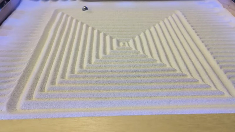
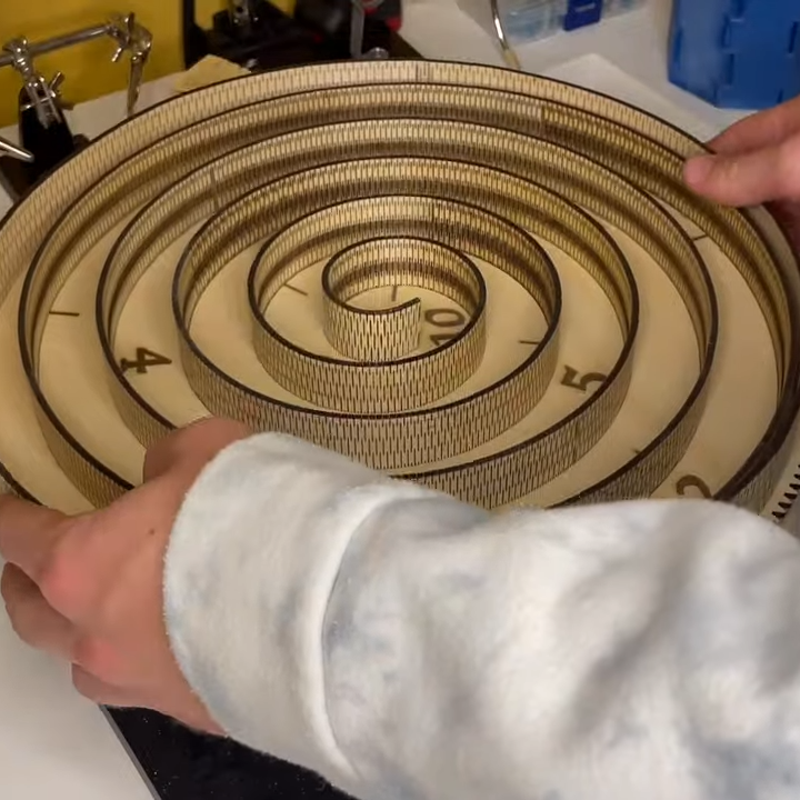
There’s nothing fun about a Sisyphean task unless you’re watching one being carried out by someone or something else. In that case, it can be mesmerizing like this Arduino-driven kinetic sand table.
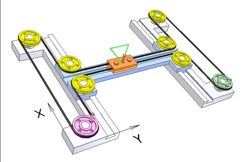
After designing some pieces to connect the rails and pulleys together, [NewsonsElectronics] let the laser cutter loose on some more 3mm stock. A pair of stepper motors connected to a CNC shield do all of the work, driving around a stack of magnets that causes the ball bearing to trudge beautifully through the sand.
Be sure to check out the videos after the break. The first is a nice demonstration, and the second is the actual build video. In the third video, [NewsonsElectronics] explains how they could write the world’s smallest GRBL code to swing this with a single Arduino. Hint: it involves removing unnecessary data from the g-code generated by Sandify.
Don’t have a laser cutter? Here’s a sand table built from 3D printer parts.