Arduino Saves Heat Pump
For home HVAC systems, heat pumps seem to be the way of the future. When compared to electric heating they can be three to four times more efficient, and they don’t directly burn fossil fuels. They also have a leg up over standard air conditioning systems since they can provide both cooling and heating, and they can even be used on water heating systems. Their versatility seems unmatched, but it does come at a slight cost of complexity as [Janne] learned while trying to bring one back to life.
The heat pump here is a Samsung with some physical damage, as well as missing the indoor half of the system. Once the damage to the unit was repaired and refilled with refrigerant, [Janne] used an Optidrive E3 inverter controlled by an Arduino Mega to get the system functional since the original setup wouldn’t run the compressor without the indoor unit attached. The Arduino manages everything else on the system as well including all of the temperature sensors and fan motor control.
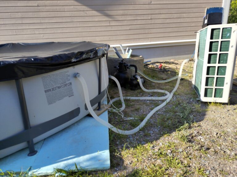
With everything up and running [Janne] connected the system to a swimming pool, which was able to heat the pool in about three hours using 60 kWh of energy. The system is surprisingly efficient especially compared to more traditional means of heating water, and repairing an old or damaged unit rather than buying a new one likely saves a significant amount of money as well. Heat pump projects are getting more common around here as well, and if you have one in your home take a look at this project which adds better climate control capabilities. to a wall mount unit.