Posts with «microcontrollers» label

Student Trolls Anti-Arduino Prof With Parasite MCU

Like some of our grouchier readers, [PodeCoet]’s Digital Sub-Systems professor loathes everyone strapping an Arduino onto a project when something less powerful and ten times as complicated will do. One student asked if they could just replace the whole breadboarded “up counter” circuit mess with an Arduino, but, since the class is centered around basic logic gates the prof shot him down. Undeterred, our troll smuggled an MCU into a chip and used it to spell out crude messages.

No Arduino? No problem. It took him 4 tries but [PodeCoet] hollowed out the SN74LS47N display driver from the required circuit and made it the puppet of a PIC16F1503 controller. The PIC emulated the driver chip in every way – as ordered it showed the count up and down – except when left unattended for 15 seconds. Then instead of digits the PIC writes out “HELLO”, followed by three things normally covered by swimsuits and lastly a bodily function.

For such a simple hack it is wonderfully and humorously documented. There are annotated progress/failure pictures and video of the hack working.

It is not as elaborate as the microscopic deception in the infamously impossible 3 LED circuit, but it gets to the point sooner.


Filed under: cons, Microcontrollers
Hack a Day 25 Dec 18:01

Programmable Lithium Charger Shield for Arduino

Surely you need yet another way to charge your lithium batteries—perhaps you can sate your desperation with this programmable multi (or single) cell lithium charger shield for the Arduino<! Okay, so you’re not><em>hurting</em> for another method of juicing up your batteries. If you’re a regular around these parts of the interwebs, you’ll recall the <a href="http://hackaday.com/2014/09/21/a-li-ion-battery-charging-guide/">lithium charging guide</a> and that <a href="http://hackaday.com/2014/09/05/an-obsessively-thorough-battery-and-more-showdown/">rather incredible, near-encyclopedic rundown of both batteries and chargers</a>, which likely kept your charging needs under control.</p> <p>That said, this shield by Electro-Labs might be the perfect transition for the die-hard-’duino fanatic looking to migrate to tougher projects. The build features an LCD and four-button interface to fiddle with settings, and is based around an LT1510 constant current/constant voltage charger IC. You can find the schematic, bill of materials, code, and PCB design on the Electro-Labs webpage, as well as a brief rundown explaining how the circuit works. Still want to add on the design? Throw in <a href="http://hackaday.com/2014/07/16/finally-an-easy-to-make-holder-for-lithium-ion-batteries/">one of these Li-ion holders</a> for quick battery swapping action.</p> <p>[via <a href="http://embedded-lab.com/blog/?p=9644">Embedded Lab</a>]</p><br />Filed under: <a href="http://hackaday.com/category/arduino-hacks/">Arduino Hacks</a>, <a href="http://hackaday.com/category/microcontrollers/">Microcontrollers</a> <a><img src="http://feeds.wordpress.com/1.0/comments/hackadaycom.wordpress.com/138748/" /></a> <img src="http://pixel.wp.com/b.gif?host=hackaday.com&blog=4779443&post=138748&subd=hackadaycom&ref=&feed=1" />

Morse Decoder’s Lean and Sexy Search Algorithm

Often the Morse Code centered projects that we feature are to help you practice transmitting messages. This one takes a tack and builds an automatic decoder. We think [Nicola Cimmino's] project is well worth featuring simply based on his explanation of the Digital Signal Processing used on the signal coming in from the microphone. Well done. But he’s really just getting warmed up.

What makes this really stand out is a brilliant algorithm that allows conversion from Morse to ASCII using a lookup table of only 64 bytes. This provides enough room for A-Z and 0-9 without chance of collision but could be expanded to allow for more characters. Below is a concise description of how the algorithm works but make sure you take the time to read [Nicola's] project description in its entirety.

The algorithm can be decribed as follows. Have an index inside the lookup string inizialied to zero. Have an initial dash jump size of 64. At every received element (dot or dash) halve the initial dash jump and then increase by 1 the index inside the lookup string if a dot was received and by dash jump size if a dash was received. Repeat until a letter separator is reached, at that point the index inside the lookup string will point to the ASCII corresponding to the decoded morse.

Have you heard of this technique before? If so, tell us about it in the comments below. Before you jump all over this one, realize that Magic Morse uses a different technique.


Filed under: Microcontrollers, radio hacks

When Worlds Collide: 68008 Bootstrapped by an Arduino Uno

[Peter Bjornx] brings classic microprocessors and modern microcontrollers together with his Arduino bootstrapped 68008 computer. The Motorola 68008 is the 8-bit external bus version of the well-known 68000 (or 68k) microprocessor. A friend gave [Peter] one of these chips, so he built a simple computer around it.

This isn’t one of those clean retrocomputers with every connection carefully planned out and wire wrapped. [Peter's] created a true hack – a working 68k system on a breadboard created with whatever he had on hand at the time. The real gem of this system is the ROM. [Peter] replaced an EPROM chip with an Arduino.

In the not-so-good-old-days, microprocessors (and many microcontrollers) ran from an external ROM chip. This often was a UV-erasable EPROM. Carefully compiled code was burned into the EPROM with a device programmer. If the code wasn’t perfect, the EPROM had to be pulled and placed under a UV lamp for 20 minutes or so to erase it before it was time to try again. EPROM emulators were available, but they were way too expensive for the hobbyist.

Thankfully those days are far behind us now with the advent of EEPROM and then Flash. [Peter] didn’t want to revisit the past either, so he wrote a simple Arduino sketch which allowed it to act as an EPROM emulator, including address logging via the serial port.

The design still caused [Peter] some headaches, though. His major problem was a classic 68k issue, /DTACK timing. /DTACK or Data Transfer Acknowledge is one of several bus control signals used by the 68k. When the 68k performs a read from the data bus, it waits for /DTACK before it transfers data. The Arduino was too slow to release /DTACK in this case, which caused the 68k to think every read was immediately completed. There is a much clearer explanation of the 68k bus cycles on this Big Mess O Wires page. [Peter's] solution was simple – a D flip-flop connected to the address strobe took care of the timing issues.

It took quite a bit of tinkering, but the system eventually worked. Peter was able to run the 68008 from its reset vector into a simple loop using the Arduino. It’s only fitting that the 68k program loaded by the Arduino was an LED blinker, everyone’s favorite hardware Hello World.

Thanks [Robert!]


Filed under: classic hacks, Microcontrollers

TFT LCDs Hit Warp Speed with Teensy 3.1

[Paul Stoffregen], known as father of the Teensy, has leveraged the Teensy 3.1’s hardware to obtain some serious speed gains with SPI driven TFT LCDs. Low cost serial TFT LCDs have become commonplace these days. Many of us have used Adafruit’s TFT LCD library  to drive these displays on an Arduino. The Adafruit library gives us a simple API to work with these LCDs, and saves us from having to learn the intricacies of various driver chips.

[Paul] has turbocharged the library by using hardware available on Teensy 3.1’s 32 Freescale Kinetis K20 microcontroller. The first bump is raw speed. The Arduino’s ATmega328 can drive the SPI bus at 8MHz, while the Teensy’s Kinetis can ramp things up to 24MHz.

Speed isn’t everything though. [Paul] also used the Freescale’s 4 level FIFO to buffer transfers. By using a “Write first, then block until the FIFO isn’t full” algorithm, [Paul] ensured that new data always gets to the LCD as fast as possible.

Another huge bump was SPI chip select. The Kinetis can drive up to 5 SPI chip select pins from hardware. The ATmega328 doesn’t support chip selects. so they must be implemented with GPIO pins, which takes even more time.

The final result is rather impressive. Click past the break to see the ATmega based Arduno race against the Kinetis K20 powered Teensy 3.1.

Paul’s library is open source and available on Github.


Filed under: Microcontrollers
Hack a Day 18 Aug 18:00
arduino  lcd  microcontrollers  paul  pjrc  spi  teensy  teensy 3.1  tft  

Quick and Dirty RFID Door Locks Clean up Nice

[Shawn] recently overhauled his access control by fitting the doors with some RFID readers. Though the building already had electronic switches in place, unlocking the doors required mashing an aging keypad or pestering someone in an adjacent office to press a button to unlock them for you. [Shawn] tapped into that system by running some wires up into the attic and connecting them to one of two control boxes, each with an ATMega328 inside. Everything functions as you would expect: presenting the right RFID card to the wall-mounted reader sends a signal to the microcontroller, which clicks an accompanying relay that drives the locks.

You may recall [Shawn's] RFID phone tag hack from last month; the addition of the readers is the second act of the project. If you’re looking to recreate this build, you shouldn’t have any trouble sourcing the same Parallax readers or building out your own Arduino on a stick, either. Check out a quick walkthrough video after the jump.


Filed under: Arduino Hacks, Microcontrollers

Meet the WIDGEDUINO

Arduino has made a name for itself by being easy to use and has become an excellent tool for rapid prototyping of an idea. If one wakes up in the middle of the night in a eureka moment and hammers out a contraption – using an Arduino as the brains is about as fast and easy as it gets.

With that said, the WIDGEDUINO aims at making this process even faster and easier. Bristling with an array of meters, graphs and data entry widgets, the WIDGEDUINO is sure to be a hit with hackers, makers and engineers alike.

It’s based on the .NET framework and was designed with Visual Studio Windows Presentation Foundation. The user simply writes a sketch using the WIDGEDUINO library, and connects to a PC via serial or Ethernet to gain access to the assortment of awesome widgets.

You can find a few examples here. We hope the creators will keep us updated on the progress of this impressive project. Be sure to stick around after the break for a video demonstrating what the WIDGEUINO can do.


Filed under: Arduino Hacks, Microcontrollers, news

Project: Clock Four – Scrolling text clock

Introduction

Time for another instalment in my highly-irregular series of irregular clock projects.  In this we have “Clock Four” – a scrolling text clock. After examining some Freetronics Dot Matrix Displays in the stock, it occurred to me that it would be neat to display the time as it was spoken (or close to it) – and thus this the clock was born. It is a quick project – we give you enough to get going with the hardware and sketch, and then you can take it further to suit your needs.

Hardware

You’ll need three major items – An Arduino Uno-compatible board, a real-time clock circuit or module using either a DS1307 or DS3232 IC, and a Freetronics DMD. You might want an external power supply, but we’ll get to that later on.

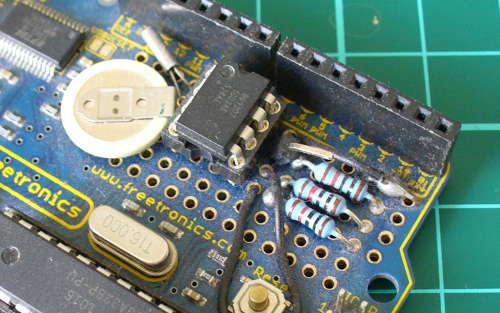
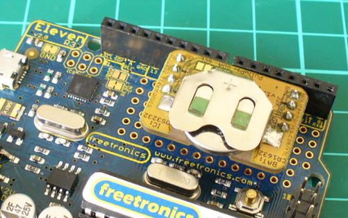
The first stage is to fit your real-time clock. If you are unfamiliar with the operation of real-time clock circuits, check out the last section of this tutorial. You can build a RTC circuit onto a protoshield or if you have a Freetronics Eleven, it can all fit in the prototyping space as such:

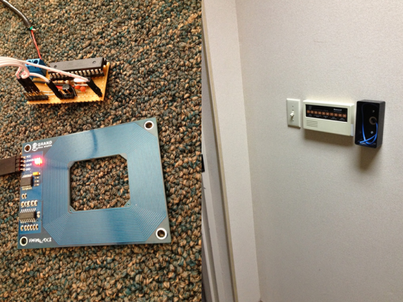
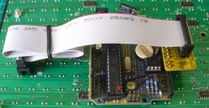
If you have an RTC module, it will also fit in the same space, then you simply run some wires to the 5V, GND, A4 (for SDA) and A5 (for SCL):

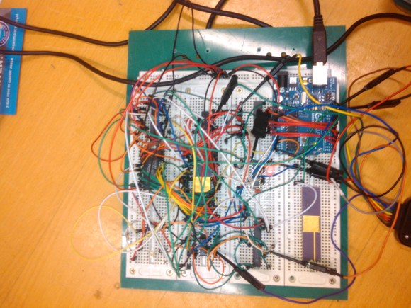
By now I hope you’re thinking “how do you set the time?”. There’s two answers to that question. If you’re using the DS3232 just set it in the sketch (see below) as the accuracy is very good, you only need to upload the sketch with the new time twice a year to cover daylight savings (unless you live in Queensland). Otherwise add a simple user-interface – a couple of buttons could do it, just as we did with Clock Two. Finally you just need to put the hardware on the back of the DMD. There’s plenty of scope to meet your own needs, a simple solution might be to align the control board so you can access the USB socket with ease – and then stick it down with some Sugru:

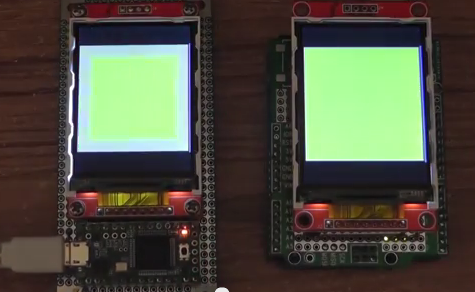
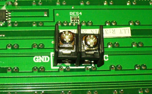
With regards to powering the clock – you can run ONE DMD from the Arduino, and it runs at a good brightness for indoor use. If you want the DMD to run at full, retina-burning brightness you need to use a separate 5 V 4 A power supply. If you’re using two DMDs – that goes to 8 A, and so on. Simply connect the external power to one DMD’s terminals (connect the second or more DMDs to these terminals):

The Arduino Sketch

You can download the sketch from here. Please use IDE v1.0.1 . The sketch has the usual functions to set and retrieve the time from DS1307/3232 real-time clock ICs, and as usual with all our clocks you can enter the time information into the variables in void setup(), then uncomment setDateDs1307(), upload the sketch, re-comment setDateDs1307, then upload the sketch once more. Repeat that process to re-set the time if you didn’t add any hardware-based user interface.

Once the time is retrieved in void loop(), it is passed to the function createTextTime(). This function creates the text string to display by starting with “It’s “, and then determines which words to follow depending on the current time. Finally the function drawText() converts the string holding the text to display into a character variable which can be passed to the DMD.

And here it is in action:

Conclusion

This was a quick project, however I hope you found it either entertaining or useful – and another random type of clock that’s easy to reproduce or modify yourself. We’re already working on another one which is completely different, so stay tuned.

In the meanwhile have fun and keep checking into tronixstuff.com. Why not follow things on twitterGoogle+, subscribe  for email updates or RSS using the links on the right-hand column? And join our friendly Google Group – dedicated to the projects and related items on this website. Sign up – it’s free, helpful to each other –  and we can all learn something.

The post Project: Clock Four – Scrolling text clock appeared first on tronixstuff.

Open Hardware Pinoccio Is A Wireless, Web-Ready Microcontroller

I met Eric Jennings at the Hardware Innovation Workshop last May where he was showing off plans for a new wireless Arduino-compatible mircocontroller board. After going through nine prototypes since then, he and co-founder Sally Carson launched the Pinoccio this week. Here’s how Eric describes the platform: Pinoccio is a [...]

Read the full article on MAKE

DIY Rickroller

Have you ever been Rickrolled? The bait-and-switch web gag is a web classic. But why confine the cheesy music of Rick Atley to the internet? Now you don't have to thanks to computer engineer Zach Ratner.

Read the full article on MAKE