Posts with «kit» label

Kit Review – Sinclair Cambridge Calculator

Introduction

It’s no secret that I enjoy kit reviews – it’s always interesting to see how well a kit goes together, along with the quality of parts, documentation and so on. But what about kits from the past? And not 2003. Recently a very rare opportunity to purchase a sealed Sinclair Radionics Cambridge calculator kit appeared on ebay – so it was ordered rapidly and duly delivered to the office. And thus the subject of this review.

You may be familiar with the Sinclair name – Sir Clive Sinclair introduced many innovative and interesting products to the UK and world markets in his own style. Some were a raging success, such as the ZX-series home computers – and some were not. However in 1973 Sinclair introduced a range of calculators, starting with the “Cambridge”. It’s a simple four-function calculator with an LED numeric display and a somewhat dodgy reputation.

The design evolved rapidly and at the Mark III stage it was sold assembled and as a kit. At the time handheld calculators were quite expensive, so the opportunity to save money and get one in kit form would have been quite appealing to the enthusiast – in January 1974 the kit retailed in the UK for 24.95 (+ VAT):

Assembly

Putting the Cambridge together required a balance of healthy paranoia, patience and woodworker mentality (measure twice – cut once). There wouldn’t be any second chances, or quick runs down to Altronics for a replacement part (well … there was one) so care needed to be taken. If you’re curious about the details, I’ve uploaded 82 full-resolution images from the build, including both instruction manuals and schematic onto flickr. Now to get started.

 The kit arrives in a neat, retail-orientated package:

… with the components on one side of the foam:

… and the other side held he assembly guide (underneath which was a very short length of solder and the carrying case):

At this point I was starting to have doubts, and thought it would be better off in storage. But what fun would that be? So out with the knife and the shrink-wrap was gone, revealing the smell of 1974 electronics. Next to whip out the instructions and get started:

They are incredibly detailed, and allow for two variations of enclosure and also offer tips on good construction – as well as the schematic, BOM and so on. Like any kit it’s wise to take stock of the components, which gave us the PCB:

… the passives, diodes and transistor – and some solder wick:

At this point it turned out the all but one of the resistors were anywhere near the specified values in the instructions, and I wasn’t going to trust those electrolytic capacitors after 39 years. The replacement parts were in stock – including the original 1n914 diode that was missing from the kit. Thanks Clive. There was also a coil of unknown value:

… and the ICs, which included the brains of the operation – a General Instrument Microelectronics CZL-550:

… and an ITT 7105N:

… a bag of battery clips, buttons and adhesive-backed foam (which deteriorated nicely):

At this point it was time to fire up the Hakko and start soldering, not before giving the PCB a good hit with the Servisol cleaner spray. I was worried about the tracks lifting while soldering due to heat and old-age, however the PCB held up quite well. The first step is to solder in the clips that hold (just) four AAA cells:

… then the resistors and diodes:

… followed by the transistor, ITT IC, ceramic capacitor and coil:

Uh-oh – that ceramic went in the wrong hole. One leg was soldered where the coil was to sit. Without wanting to damage the PCB, de-soldering it was a slow, slow process. Then of course I didn’t have a ) 3.3nF in stock, so a quick spin to Altronics solved that problem (I bought 50) – one of which finally went in:

The transistor was also a bit of a puzzle, I hadn’t seen that enclosure type and the manual wasn’t much help, so the semiconductor analyser tester solved that problem:

The next step was to fit the display, which is wedged in the large gap at the top of the PCB. The tracks on the PCB are supposed to meet the display, however time had affected the tracks on the display module, so I soldered small wire links across the gaps:

Following the display were the two (new) electrolytics:

And now to the main IC. There wasn’t any second chances with this, and after some very gently pin-bending it dropped in nicely:

After a short break it was time to assemble the keypad, which went smoothly. After cleaning all the foam dust off the buttons, they dropped in to their frame which in turn dropped into the enclosure, followed by the keypad layers:

You can also see in the display window and shroud have been fitted. From here the PCB is inserted:

… and a sticker from years gone by, as well as the metal clip over the bottom of the power switch. At this point a quick test with four AAA cells showed signs of life on the display, so the rear enclosure could be fitted:

Now for the battery and final cover, and it’s ready to go!

The digits are quite sharp, but very small – and set back from the window. This makes photography quite difficult. At the time if your calculator didn’t work, you could send it off to Sinclair and they’d repair or possibly replace it for you:

Using the Cambridge

Well it works, so you have a calculator which is genuinely useful. However the Cambridge has a few quirks, which are attributed to the basic functions of the main IC. For example, when entering numbers the screen is filled with leading zeros until you select a function, however by using the manual you can complete complex work including square roots, percentages, loan repayments and much more.

Furthermore the Cambridge is quite the silent achiever, you can work with numbers as small as 1x10E-20 and up to 9.9999999E79. You simply enter the numbers in decimal form (e.g. 0.000000000123) … even though the display won’t show all the digits, they’re being stored in a register. To then extract the result, you continually multiply or divide by ten (making note of how many times you do that) until the digits appear on the screen. It sounds nuts today – but in 1974 it would have been a cheap way of avoiding a more expensive calculator. In the following video you can see th Cambridge in action, plus the results of dividing by zero:

More about Sinclair

The following video is a BBC dramatisation of the rise of the home computer in the UK market, and the competition between Sir Clive Sinclair (Sinclair) and Adam Curry (Acorn Computers) – which is quite entertaining:

You can find out more about the history of Sir Clive Sinclair here, and the calculator range here. If anyone can connect us with a Science of Cambridge MK14 computer, contact us.

Conclusion

From a 1974 perspective, that would have been a great kit to make, with some love and care it would have been successful. By today’s standards it was quite average – however you can’t really judge it from a 2013 perspective. Nevertheless, kudos to Sir Clive Sinclair for his efforts in knocking out a useful product as a kit. If you’re a collector, and see a sealed unit on ebay or elsewhere, give it a whirl. Just take your time, “think before doing”, and replace as many of the components as possible. I’ve put all the images in full resolution up on flickr, so you can follow along in more detail.

And while you’re here – are you interested in Arduino? Check out my new book “Arduino Workshop” from No Starch Press.

In the meanwhile have fun and keep checking into tronixstuff.com. Why not follow things on twitterGoogle+, subscribe  for email updates or RSS using the links on the right-hand column? And join our friendly Google Group – dedicated to the projects and related items on this website. Sign up – it’s free, helpful to each other –  and we can all learn something.


The post Kit Review – Sinclair Cambridge Calculator appeared first on tronixstuff.

Kit Review – Maniacal Labs Epoch Clock

Introduction

The subject of our latest kit review is the “Epoch Clock” from Maniacal Labs, a new organisation started by three young lads with some interesting ideas. Regular readers will know we love a clock – so when the opportunity came to review this one, we couldn’t say no.

At this point you may be thinking “what is Epoch time anyway?”. Good question! It is the number of seconds elapsed since the first of January, 1970 (UTC) – and used by Unix-based computers as the start of their time universe. (For more on the theory of Epoch time, check out Wikipedia). For example – 1379226077 Epoch time is Sun, 15 Sep 2013 06:21:17 GMT. That’s a lot of seconds. If you’re curious, you can do more calculations with the EpochTime website.

Moving forward, this clock kit will show Epoch time in full 32-bit binary glory, using a DS1307 real-time clock IC (with backup battery) and is controlled with an ATmega328P-PU – so you can modify the code easily with the Arduino IDE or WinAVR (etc).

Assembly

The creators have spent a lot of time on not only the packaging and out-of-box-experience, but also the documentation and setup guide – so as long as you’re fine with simple through-hole soldering the kit will not present any challenges. The kit arrives in a sturdy box:

… with well packaged components. Everything is included for the finished product, as well as IC sockets, the RTC backup battery and a USB cable so you can power the clock from a USB hub:

The PCB is a good thickness, and has a clear silk-screen and solder mask:

Construction is simple, just follow the step-by-step instructions. Starting with the USB socket for power:

… then the resistors:

… the LEDs:

… all 32 of them. Note that the LEDs don’t sit flush with the PCB, so a little effort is required to keep them aligned:

 Then the rest of the components just fit as expected. I’ve also added the included header pins for an FTDI programming cable and ICSP to keep my options open:

Then simply fit the battery, insert the ICs and you’re done:

Using the clock

The microcontroller is pre-programmed, so you can use the clock straight away. You will however need to set the time first. To make this incredibly easy, there is a special web page that displays the current time and Epoch time, which steps you through the process of setting the time using the buttons.

Or with some code available on the kit github page and a programming cable, you can automatically sync it to the clock. Once setup, the battery will keep the current time in the RTC nicely. The clock is powered by 5V, which is easily supplied with the included USB cable, or you can always hack in your own feed.

So what does Epoch time in 32-bit binary look like? Here’s a short video of the clock in action:

Reading the time requires converting the binary number displayed with the LEDs back to a decimal number – which is of course the Epoch count of seconds since 1/1/1970. Math teachers will love this thing.

But wait, there’s more!

If you get tired of the blinking, there’s a test function which is enabled by holding down both buttons for a second, which turns the Epoch Clock into a nifty Larson Scanner:

To create your own sketches or examine the design files in more detail, it’s all on the clock github page. From a hardware perspective you have an ATmega328P-PU development board with a DS1307 battery-backed real-time clock – with 32 LEDs. So you could also create your own kind of clock or other multi-LED blinking project without too much effort. Review the EpochClockSchematic (.pdf) to examine this in more detail.

Conclusion

I really enjoyed this kit – it was easy to assemble, I learned something new and frankly the blinking LEDs can be quite soothing. The clock would make a great for a conversation-starter in the office, or would make an ideal gift for any Sheldon Cooper-types you might be associated with. Or have competitions to see who can convert the display to normal time. After shots.

Nevertheless it’s a fun and imaginative piece of kit, fully Open Hardware-compliant – and if you’ve made it this far – get some and have fun. Full-sized images are on flickr. Interested in Arduino? Check out my new book “Arduino Workshop” from No Starch Press.

In the meanwhile have fun and keep checking into tronixstuff.com. Why not follow things on twitterGoogle+, subscribe  for email updates or RSS using the links on the right-hand column? And join our friendly Google Group – dedicated to the projects and related items on this website. Sign up – it’s free, helpful to each other –  and we can all learn something.

[Note – The kit reviewed was a promotional consideration from Maniacal Labs]

The post Kit Review – Maniacal Labs Epoch Clock appeared first on tronixstuff.

Tronixstuff 15 Sep 10:29

Australian Electronics Nostalgia – Talking Electronics Kits

Introduction

From 1981, Australian electrical engineer Colin Mitchell started publishing his home-grown electronics magazine “Talking Electronics”. His goal was to get people interested and learning about electronics, and more so with a focus on digital electronics. It was (and still is) a lofty goal – in which he succeeded. From a couple of rooms in his home the magazine flourished, and many projects described within were sold as kits. At one stage there were over 150 Talking Electronics kits on the market. You could find the books and kits in retail outlets such as Dick Smith Electronics, and for a short while there was a TE store in Moorabbin (Victoria). Colin and the team’s style of writing was easy to read and very understandable – but don’t take my word for it, you can download the magazines from his website (they’re near the bottom of the left column). Dave Jones recently interviewed Colin, and you can watch those for much more background information.

Over fifteen issues you could learn about blinking LEDs all the way to making your own expandable Z80 board computer, and some of the kits may still be available. Colin also published a series of tutorial books on electronics, and also single-magazine projects. And thus the subjects of our review … we came across the first of these single-issue projects from 1981 – the Mini Frequency Counter (then afterwards we have another kit):

How great is that? The PCB comes with the magazine. This is what set TE apart from the rest, and helped people learn by actually making it easy to build what was described in the magazine instead of just reading about it. For 1981 the PCB was quite good – they were silk-screened which was quite rare at the time:

And if you weren’t quite ready, the magazine also included details of a square-wave oscillator to make and a 52-page short course in digital electronics. However back to the kit…

Assembly

The kit uses common parts and I hoard CMOS ICs so building wasn’t a problem. This (original) version of the kit used LEDs instead of 7-segment displays (which were expensive at the time) so there was plenty of  careful soldering to do:

And after a while the counter started to come together. I used IC sockets just in case:

The rest was straight-forward, and before long 9 V was supplied, and we found success:

To be honest progress floundered for about an hour at this point – the display wouldn’t budge off zero. After checking the multi-vibrator output, calibrating the RC circuits and finally tracing out the circuit with a continuity tester, it turned out one of the links just wasn’t soldered in far enough – and the IC socket for the 4047 was broken So a new link and directly fitting the 4047 fixed it. You live and learn.

Operation

So – we now have a frequency counter that’s good for 100 Hz to the megahertz range, with a minimum of parts. Younger, non-microcontroller people may wonder how that is possible – so here’s the schematic:

The counter works by using a multi-vibrator using a CD4047 to generate a square-wave at 50, 500 and 5 kHz, and the three trimpots are adjusted to calibrate the output. The incoming pulses to measure are fed to the 4026 decade counter/divider ICs. Three of these operate in tandem and each divide the incoming count by ten – and display or reset by the alternating signal from the 4047. However for larger frequencies (above 900 Hz) you need to change the frequency fed to the display circuit in order to display the higher (left-most) digits of the result. A jumper wire is used to select the required level (however if you mounted the kit in a case, a knob or switch could be used).

For example, if you’re measuring 3.456 MHz you start with the jumper on H and the display reads 345 – then you switch to M to read 456 – then you switch to the L jumper and read 560, giving you 3456000 Hz. If desired, you can extend the kit with another PCB to create a 5-digit display. The counter won’t be winning any precision contests – however it has two purposes, which are fulfilled very well. It gives the reader an inexpensive piece of test equipment that works reasonably well, and a fully-documented project so the reader can understand how it works (and more).

And for the curious –  here it is in action:

[Update 20/07/2013] Siren Kit

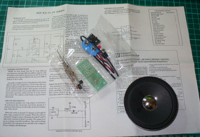
Found another kit last week, the Talking Electronics “DIY Kit #31 – 9V siren”. It’s an effective and loud siren with true rise and fall, unlike other kits of the era that alternated between two fixed tones. The packaging was quite strong and idea for mail-order at the time:

The label sells the product (and shows the age):

The kit included every part required to work, apart from a PP3 battery, and a single instruction sheet with a good explanation of how the circuit works, and some data about the LM358:

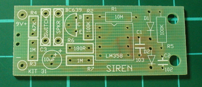
… and as usual the PCB was ahead of its’ time with full silk-screen and solder mask:

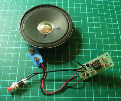
Assembly was quite straight-forward. The design is quite compact, so a lot of vertical resistor mounting was necessary due to the lack of space. However it was refreshing to not have any links to fit. After around twenty minutes of relaxed construction, it was ready to test:

It’s a 1/2 watt speaker, however much louder than originally anticipated:

Once again, another complete and well-produced kit.

Conclusion

That was a lot of fun, and I’m off to make the matching square-wave oscillator for the frequency counter. Kudos to Colin for all those years of publication and helping people learn. Lots of companies bang on about offering tutorials and information on the Internet for free, but Colin has been doing it for over ten years. Check out his Talking Electronics website for a huge variety of knowledge, an excellent electronics course you can get on CD – and go easy on him if you have any questions.

Full-sized images available on flickr. This kit was purchased without notifying the supplier.

And if you made it this far – check out my new book “Arduino Workshop” from No Starch Press.

In the meanwhile have fun and keep checking into tronixstuff.com. Why not follow things on twitterGoogle+, subscribe  for email updates or RSS using the links on the right-hand column? And join our friendly Google Group – dedicated to the projects and related items on this website. Sign up – it’s free, helpful to each other –  and we can all learn something.

The post Australian Electronics Nostalgia – Talking Electronics Kits appeared first on tronixstuff.

Plantoid Robot: Rimor Mundus, Terrapod v2

Primary image

What does it do?

Uses data based on the condition of a plant in a terraruim ecosystem to explore and react to the outer world.


Cost to build

$160,00

Embedded video

Finished project

Number

Time to build

8 hours

Type

legs

URL to more information

Weight

300 grams

read more

Review: Gooligum Electronics PIC Training Course and Development Board

Introduction

[Updated 18/06/2013]

There are many types of microcontrollers on the market, and it would be fair to say one of the two most popular types is the Microchip PIC series. The PICs are great as there is a huge range of microcontrollers available across a broad range of prices. However learning how to get started with the PIC platform isn’t exactly simple. Not that we expect it to be, however a soft start is always better. There are some older books, however they can cost more than $100 – and are generally outdated. So where do you start?

It is with this problem in mind that led fellow Australian David Meiklejohn to develop and offer his PIC Training Course and Development Board to the marketplace via his company Gooligum Electronics.

In his words:

There is plenty of material available on PICs, which can make it daunting to get started.  And some of the available material is dated, originally developed before modern “flash” PICs were available, or based on older devices that are no longer the best choice for new designs.  Our approach is to introduce PIC programming and design in easy stages, based on a solid grounding in theory, creating a set of building blocks and techniques and giving you the confidence to draw on as we move up to more complex designs.

So in this article we’ll examine David’s course package. First of all, let’s look at the development board and inclusions. Almost everything you will need to complete all the lessons is included in the package, including the following PIC microcontrollers:

You can choose to purchase the board in kit form or pre-assembled. If you enjoy soldering, save the money and get the kit – it’s simple to assemble and a nice way to spend a few hours with a soldering iron.

Although the board includes all the electronic components and PICs – you will need are a computer capable of running Microchip MPLAB software, a Microchip PICkit3 (or -2) programming device and an IC extractor. If you’re building the kit, a typical soldering iron and so on will be required. Being the  ultra-paranoid type, I bought a couple extra of each PIC to have as spares, however none were damaged in my experimenting. Just use common-sense when handling the PICs and you will be fine.

Assembly

Putting the kit board together wasn’t difficult at all. There isn’t any surface-mount parts to worry about, and the PCB is silk-screened very well:

The rest of the parts are shipped in antistatic bags, appropriately labelled and protected:

Assembly was straight forward, just start with the low-profile parts and work your way up. The assembly guide is useful to help with component placement. After working at a normal pace, it was ready in just over an hour:

The Hardware

Once assembled (or you’ve opened the packaging) the various sections of the board are obvious and clearly labelled – as they should be for an educational board. You will notice a large amount of jumper headers – they are required to bridge in and out various LEDs, select various input methods and so on. A large amount of jumper shunts is included with the board.

It might appear a little disconcerting at first, but all is revealed and explained as you progress through the lessons. The board has decent rubber feet, and is powered either by the PICkit3 programmer, or a regulated DC power source between 5 and 6V DC, such as from a plug-pack if you want to operate your board away from a PC.

However there is a wide range of functions, input and output devices on the board – and an adjustable oscillator, as shown in the following diagram:

The Lessons

There is some assumed knowledge, which is a reasonable understanding of basic electronics, some computer and mathematical savvy and the C programming language.

You can view the first group of lessons for free on the kit website, and these are included along with the additional lessons in the included CDROM. They’re in .pdf format and easy to read. The CDROM also includes all the code so you don’t have to transcribe it from the lessons. Students start with an absolute introduction to the system, and first learn how to program in assembly language in the first group of tutorials, followed by C in the second set.

This is great as you learn about the microcontroller itself, and basically start from the bottom. Although it’s no secret I enjoy using the Arduino system – it really does hide a lot of the actual hardware knowledge away from the end user which won’t be learned. With David’s system – you will learn.

If you scroll down to the bottom of this page, you can review the tutorial summaries. Finally here’s a quick demonstration of the 7-segment displays in action:

Update – 18/06/2013

David has continued publishing more tutorials for his customers every few months – including such topics as the EEPROM and pulse-width modulation. As part of the expanded lessons you can also get a pack which allows experimenting with electric motors that includes a small DC motor, the TI SN75441 h-bridge IC, N-channel and P-channel MOSFETS and more:

So after the initial purchase, you won’t be left on your own. Kudos to David for continuing to support and develop more material for his customers.

Where to from here? 

Once you run through all the tutorials, and feel confident with your knowledge, the world of Microchip PIC will be open to you. Plus you now have a great development board for prototyping with 6 to 14-pin PIC microcontrollers. Don’t forget all the pins are brought out to the row of sockets next to the solderless breadboard, so general prototyping is a breeze.

Conclusion

For those who have mastered basic electronics, and have some C or C-like programming experience from using other development environments or PCs – this package is perfect for getting started with the Microchip PIC environment. Plus you’ll learn about assembly language – which is a good thing. I genuinely recommend this to anyone who wants to learn about PIC and/or move into more advanced microcontroller work. And as the entire package is cheaper than some books –  you can’t go wrong. The training course is available directly from the Gooligum website.

Disclaimer – The Baseline and Mid-Range PIC Training Course and Development Board was a promotional consideration from Gooligum Electronics.

In the meanwhile have fun and keep checking into tronixstuff.com. Why not follow things on twitterGoogle+, subscribe  for email updates or RSS using the links on the right-hand column? And join our friendly Google Group – dedicated to the projects and related items on this website. Sign up – it’s free, helpful to each other –  and we can all learn something.

The post Review: Gooligum Electronics PIC Training Course and Development Board appeared first on tronixstuff.

Arduino-Controlled Robots Webcast With Author Michael Margolis

Considering a robot for your next Arduino project? Even if you're not, this free webcast with the author of the Arduino Cookbook will teach you plenty of practical information about controlling motors and using sensors with Arduino.

Read the full article on MAKE

MAKE » Arduino 23 Oct 16:14

Romibo therapeutic robot, eyes-on (video)

Between old Paro the robo seal and the original iteration of Keepon, we've seen plenty of adorable robots designed for therapeutic purposes. Romibo's creators have no qualms admitting that their own creation is following in those cuddly footsteps, but what sets their furry 'bot apart from much of the competition is a focus on (relative) affordability. For starters, there's the fact that Romibo is being offered up as an open-source project online, letting do-it-yourselfers build their own versions and contribute custom designs.

The company's also hoping families will get into the act, making sure that Romibo is "able to be assembled by a neurotypical child 10+ and a parent" -- and then there are the plans to offer up workshops to let folks build robots to be donated to special needs facilities. Once built, Romibo can drive around, blink its eyes, speak and move its antennae. Crack it open and you'll find WiFi, bluetooth, light sensors, an IR Proximity sensor, accelerometers and a big 'ole Arduino Mega. There's a certain amount of autonomous functionality (watch in the video below as Romibo's handler warns about it driving off the edge of the table), or you can control the robot via an iPad app. You can also use an SD card to help teach it some new words.

Continue reading Romibo therapeutic robot, eyes-on (video)

Filed under: Robots

Romibo therapeutic robot, eyes-on (video) originally appeared on Engadget on Tue, 23 Oct 2012 09:46:00 EST. Please see our terms for use of feeds.

Permalink | Email this | Comments

Build your own drum pad

With the Drum kit – Kit AI by Spikenzielabs you can build an electronic drum kit. The bundle contains all of the electronics, including the piezo sensors for the drum pads. You build the drum pads yourself, and then connect the Drum Kit – Kit AI to your computer to play sounds using your favorite audio software, or use the MIDI-out port to a connected drum synthesizer.

Roberto De Nicolò (aka Rodenic) has realized an useful tutorial video showing what he has called FingerDrum. Roberto has applied a piezo sensor to each finger of a glove, allowing the triggering of individual drum sounds from his midi expander. If you think the glove is unconfortable, check out the FingerPad and turn your mouse pad into a drum pad.


Arduino Blog 17 Sep 14:38

feasibility of DIY wireless headphone kit

So, I was searching the market for what my wireless headphone options were and got quite disappointed.

As it seems, wireless used is either IR, RF (on the FM/UHF band) and Bluetooth (also 2.4Ghz seemingly working in the router's norm).

IR ... needs line of sight, small range...
RF... prone to interferences
Bluetooth... small range
2.4GHz... some reviews said they interfered with the home wireless routers


read more

Let's Make Robots 04 Sep 22:30
arduino  headphone  ideas  kit  wireless  

Wearable Fabric on the Arduino Store

We are happy to announce the first wearable kit on the Arduino Store . This kit has been made by Plug’n'Wear specifically for us. All fabrics in this kit are produced in Italy, and strongly related to a textile family business. If you want to get deeper into the story of this product have a look at Riccardo Marchesi presentation (still in Italian, soon to be traslated!) at World Wide Rome 2012.

Read over for Kit’s features

This kit features:

  1. 1x Circular Stretch Sensor Designed by Hannah Perner-Wilson, this circular knit stretch sensor works perfect when you need to detect tension in many projects.
  2. 2x Textile push button to make easy digital inputs in cloth, scarfs o bags.
  3. 2x Spools of Conductive thread, ready to be hooked over a sewing machine
  4. 2x Soft potentiometer kit will let you import analog data into your wearable project: this kit includes 1 meter of knitted conductive tape and a metal ring. Watch it in action (see video)
  5. 10x 1k ohm resistor
  6. 10x 10k ohm resistor
  7. 1x Textile perfboard is going to change the way you think of wearable circuits. You can sew or even solder components (SMD & through-hole) on this . It can be easily cut or sewn with a standard sewing machine. Washable. Size: 15 cm x 15 cm (6″ x 6″) / Pitch: 2.54 mm (0.1″)
  8. 1x Knitted Coated Copper Tape. Small conductive tape made of coated copper fine wire (112 micron). Flexible, easy to cut, sewable with a standard sewing machine, It can be easily welded ( The coating will melt and tape will be soldered). The surface of this tape has a good insulation thrughout its lenght. Resistance: 107 Ohm/m. Width: 9 mm (0.35″)
  9. 1x Analog Textile Press Button, working with a resistive principle (resistance goes down when you press it). It works as a bend sensor as well. By connecting more sensors together it is possible to make a matrix analog switch. Sensitive area 40mm x 40mm (1.57″x1.57″)
  10. 2x LilyPad LED Bright White A simple, very bright, 250mcd, white LED LilyPad

source: [arduino store]