Kit Review – Altronics Pocket Oscillator
Introduction
In this review we examine the Pocket Oscillator Kit from Altronics, based on an design from (the now defunct) February and March 1989 editions of Electronics Australia magazine. The purpose of this oscillator is to give you a high quality, portable square or sine wave generator that can be used to test audio equipment, speaker response, fool about with oscilloscopes (!), and so on. The prototype basic specifications are as follows:
- Frequency range: 41~1082 Hz and 735 Hz~18.1 kHz
- Output: 1.27V RMS sine, 1.45V peak square
- Load: 1.0V RMS sine into 330 Ω
- Distortion: 0.16% THD at 1 kHz
Assembly
The kit is packaged in typical form, without any surprises:

In the usual Altronics fashion, the instructions are accompanied with a neat “electronics reference sheet” which covers many useful topics such as resistor colour codes, various formulae, PCB track widths, pinouts and more. The kit instructions are based on the original magazine article and include a small addendum which isn’t any problem.

Unlike some kits, everything is included to create a finished product (except for the IC socket):

… including a nice enclosure which has the control instructions screen-printed on the lid…

However at this point I think the definition of a “pocket” is the same used by Sir Clive Sinclair when he had those pocket televisions. At this time I won’t use the enclosure as my drill press is in storage, however look forward to fitting the kit within at a later point. The PCB has a neat solder mask and silk screen:


Assembly was pretty straight forward, the original design has tried to minimise PCB real-estate, so all the resistors are mounted vertically. The signal diodes take this a step further – each pair needs to be soldered together:

… then the pair is also mounted vertically:

However it all works in the end. The rest of the circuit went together well, and we used our own IC socket for the opamp:

From this point you need to wire up the power, switches and potentiometers:

… and consider mounting the whole lot in the enclosure (or before assembly!):

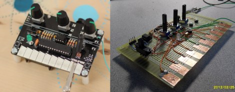
However as mentioned earlier, I just went for the open octopus method for time being:

How it works
The oscillator is based around the Texas Instruments TL064 opamp, and due to copyright I can’t give you the schematic. For complete details on the oscillator, either purchase the kit or locate the February and March 1989 edition of Electronics Australia magazine. However the waveforms from the oscillator looked good (as far as they can on a DSO):


Conclusion
The oscillator works well, however the PCB layout could have been a little lot easier on the end-user. It’s time for a redesign, possibly put all the contacts for external switches around the perimeter – and allow space for the diodes to lay normally. Nevertheless – this is a neat kit, and still quite popular after all these years. For the price you get a few hours of kit fun and a useful piece of test equipment. So if you’re into audio or experimenting, check it out. Full-sized images are available on flickr.
And while you’re here – are you interested in Arduino? Check out my new book “Arduino Workshop” from No Starch Press – also shortly available from Altronics.

In the meanwhile have fun and keep checking into tronixstuff.com. Why not follow things on twitter, Google+, subscribe for email updates or RSS using the links on the right-hand column? And join our friendly Google Group – dedicated to the projects and related items on this website. Sign up – it’s free, helpful to each other – and we can all learn something.
[Note – kit purchased without notifying the supplier]
The post Kit Review – Altronics Pocket Oscillator appeared first on tronixstuff.