Posts with «hackaday columns» label

Hackaday Links: July 12, 2015

Adafruit is working on a series of videos that’s basically Sesame Street for electronics. G is for Ground is out, where [Adabot] discovers pipes and lightning rods are connected to ground. Oh, the rhyming. Here’s the rest of the videos so far. We can’t wait for ‘Q is for Reactive Power’.

Think you’re good enough to build an airlock 70 cubic meters in volume that can cycle once every thirty seconds? How about building a 500 mile long steel tube with zero expansion joints across active fault lines? Can you stop a 3 ton vehicle traveling at 700 miles per hour in fifteen seconds? These are the near-impossible engineering challenges demanded of the hyperloop. The fact that no company will pay for this R&D should tell you something, but that doesn’t mean you still can’t contribute.

Calling everyone that isn’t from away. [Paul] lives near Augusta, Maine and can’t find a hackerspace. Augusta is the capital of the state, so there should be a hackerspace nearby. If you’re in the area, go leave a message on his profile.

Last week we found memristors you can buy. A few years ago, [Nyle] found them while hiking. They were crudded up shell casings, and experiments with sulfur and copper produced a memristor-like trace on a curve tracer.

Need a way to organize resistors? Use plastic bags that are the same size as trading cards.

The Arduino is too easy. It must be packaged into a format that is impossible to breadboard. It should be shaped like a banana. Open source? Don’t need that. The pins are incorrectly labelled, and will be different between manufacturing runs.


Filed under: Hackaday Columns, Hackaday links

Hackaday Links: July 5, 2015

It’s the fifth of July. What should that mean? Videos on YouTube of quadcopters flying into fireworks displays. Surprisingly, there are none. If you find one, put it up in the comments.

The original PlayStation was a Nintendo/Sony collaboration. This week, some random dude found a prototype in his attic. People were offering him tens of thousands of dollars on the reddit thread, while smarter people said he should lend it to MAME and homebrewer/reverse engineer groups. This was called out as a fake by [Vadu Amka], one of the Internet’s highly skilled console modders. This statement was sort of semi retracted. There’s a lot of bromide staining on that Nintendo PlayStation, though, and if it’s a fake, the faker deserves thousands of dollars. Now just dump the ROMs and reverse engineer the thing.

Remember BattleBots? It’s back. These are my impressions of the first two episodes: Flamethrowers are relatively common now, ‘parasitic bots’ – small, auxilliary bots fighting alongside the ‘main’ bot are now allowed. KOs only count for the ‘main’ bot. Give it a few more seasons and every bot will be a wedge. One of the hosts is an UFC fighter, which is weird, but not as weird as actually knowing some of the people competing.

Ceci n’est pas un Arduino, which means it’s from the SRL camp. No, wait. It’s a crowdfunding campaign for AS200 Industries in Providence, RI.

Wanna look incredibly sketchy? Weld (or braze, or solder) your keys to a screwdriver.

The UK’s National Museum of Computing  is looking for some people to help maintain 80 BBC Micros. The museum has a ‘classroom’ of BBC micro computers still in operation. Caps dry out, switching power supplies fail, and over the years these computers start to die. If you have the skills and want to volunteer, give it a shot.

USA-made Arduinos are now shipping. That’s the Massimo Arduino, by the way.

Win $1000 for pressing a buttonWe’re gauranteed to give away a thousand dollar gift card for the Hackaday store next Wednesday to someone who has participated in the latest round of community voting for the Hackaday Prize.


Filed under: Hackaday Columns, Hackaday links

Embed with Elliot: I2C Bus Scanning

A lot of great ICs use I2C to communicate, but debugging a non-working I2C setup can be opaque, especially if you’re just getting started with the protocol/bus. An I2C bus scanner can be a helpful first step in debugging an I2C system. Are all the devices that I think should be present actually there and responding? Do they all work at the bus speed that I’m trying to run? If you’ve got an Arduino or Bus Pirate sitting around, you’re only seconds away from scanning your I2C bus, and answering these questions.

The Lowdown: I2C in Brief

I2C is a two-wire (plus ground) communications bus and protocol. The physical layer is just two signal wires: a clock line (SCL) that’s controlled by the master, and a data line (SDA) that can be controlled by either the master or the addressed slave unit. Data is always read on the SDA line when the clock is high, and a new value is established while the clock is low. The two exceptions to this rule are the stop and start signals, where the master is allowed to raise and drop the data line while the clock is still high. Because this change shouldn’t ever happen during data transfer, the stop and start signals are easy to detect.

All data is sent in eight-bit packets and each packet is acknowledged by the recipient, whether master or slave. To start up a conversation, the master sends the start signal and then the seven-bit address of the slave device that it wants to speak to. The eighth bit in the master’s first packet tells the slave whether the master is going to transmit more data (a “write” command, a zero) or whether the master is requesting data back from the slave (a “read” value, a one).

After the eight bits are sent, the slave is required to acknowledge receipt by pulling the data line low.  This acknowledge signal is exactly what the I2C bus scanning software will need to look for in order to detect a chip with the given address on the bus.

There are, of course, a lot more complicating details to I2C. For instance, there are a whole range of permissible clock speeds at which the transmissions can take place: ranging from the default 100kHz data rate, through 400kHz “fast mode”, 1MHz “fast mode plus”, and up as far as 5MHz “ultra-fast mode”. (We await the 10MHz “super-duper, really-really-fast mode” with baited breath.) And since the bus is clocked by the SCL line, almost any slower data rate up to the maximum allowed will work just fine.

The physical lines are pulled up to a logic-high voltage level by pullup resistors, and the devices signal low by pulling the line down. This means that the voltage transitions can be a little blurry, especially on long runs or other situations where the line itself capacitively couples to the circuit. These physical factors will play a role in determining how fast you can send signals on the I2C bus, and you may need to fine-tune the pullup resistors in your particular system.

There are a surprisingly large number of other ways that things can go wrong on an I2C bus, so it’s great to be able to start debugging at the very beginning — is the slave even getting my first (address) packet at the speed I’m sending? Hence the utility of an I2C scanner.

A Scanner

A first cut at an I2C bus scanner, then, can be made by just cycling through all 127 possible slave device addresses, and checking whether or not they acknowledge. Next, you might want to re-run the same test at a bunch of different bus speeds, if you thought that you might be having troubles with signal rise- and fall-times. Finally, and we’ve never seen this implemented, it might be cool to have a database of common I2C slave device addresses so that the scanner itself can report back which particular chips it’s found.

For the Arduino, the most featureful scanner we’ve seen is posted on the Arduino forums, with the code hosted on Github, in the “sketches/MultiSpeedI2CScanner” folder.  It actually does everything that we’d want in a simple scanner: scans the entire bus at different speeds and plots the results out nicely over the serial port for perusal on your computer. It’s configured to do a full scan on reboot. Type “ps” to print only the found devices and start a scan. Bam!
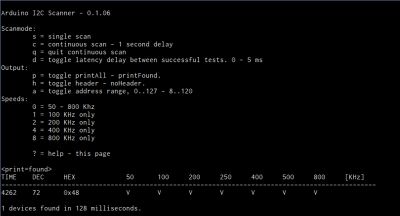
The one caveat with the Arduino scanner is that if you’ve neglected to connect pullup resistors on the SDA and SCL lines (we would never!) the scanner seems to hang somewhere when running at 800kHz. We suspect it’s waiting to become bus master and just gets stuck; we wonder why there’s not a timeout in the twi_writeTo() function in the Arduino “twi.c” library. (Anyone have a good guess?) Other speed modes worked just fine, and everything was peachy again after adding a 10k pullup resistor to SDA.

Naturally, the Bus Pirate (the swiss-army knife of serial communications) will do an I2C scan. It only runs one frequency at a time, but it’s quick enough that you can step through them all in short order. It’s got a quirk, or maybe a feature; it treats the read/write bit as part of the address, so it will test each chip in both directions. Enter the I2C mode, set the desired speed and pullup/power options, and finally type “(1)” for option 1: 7-bit address search. You should see all the devices that responded on the bus listed out for you.

Writing your own code to do a scan is surprisingly simple as well, if you know the chips you’re working with. Most microcontrollers’ dedicated hardware I2C interfaces will report error codes in a specific register. If you can figure out how to test for the “didn’t acknowledge after sending the address and data-direction packet” error, the code pretty much writes itself.

Going Further

Once you’ve got the basics verified — the slave responds when addressed at the desired speed — and your I2C setup still isn’t working, you’re on to debugging the harder problems. There are other tests you might like to do, but unfortunately they all run quickly into the slave-device specific command sets. For instance, many devices will receive a command to reply with a known device ID, or the contents of a default register, or similar. These are useful to make certain that you’ve got multi-byte commands working as expected.

If you suspect that you’re having problems with the signals not rising or falling fast enough, perhaps because you’ve seen chips respond at low speeds but not at higher ones during the scan above, you’re going to need an oscilloscope to actually probe out the analog voltages on the lines. Or try lower-value pullup resistors to speed up the rising edges and test again.

Harder to catch or infrequently occurring glitches on a multi-master I2C bus get really hard to track down really fast. But getting the simple stuff verified working first — all parts are on the addresses that you think they are — can get you set on the right path.

Good luck with your I2C projects! And if you’ve got any other useful I2C debugging tools or strategies up your sleeves, feel free to discuss in the comments.


Filed under: Hackaday Columns, Microcontrollers, peripherals hacks

Hackaday Links: May 17, 2015

Here’s a worthwhile Kickstarter for once: the Prishtina Hackerspace. Yes, that’s a Kickstarter for a hackerspace in Kosovo. Unlike most hackerspace Kickstarters, they’re already mostly funded, with 20 days to go. If we ever get around to doing the Istanbul to Kaliningrad hackerspace tour, we’ll drop by.

Codebender is a web-based tool that allows you to code and program an Arduino. The Chromebook is a web-based laptop that is popular with a few schools. Now you can uses Codebender on a Chromebook. You might need to update your Chromebook to v42, and there’s a slight bug in the USB programmers, but that should be fixed in a month or so.

Here’s a great way to waste five minutes. It’s called agar.io. It’s a multiplayer online game where you’re a cell, you eat dots that are smaller than you, and bigger cells (other players) can eat you. [Morris] found the missing feature: being able to find the IP of a server so you can play with your friends. This feature is now implemented in a browser script. Here’s the repo.

The FAA currently deciding the fate of unmanned aerial vehicles and systems, and we’re going to live with any screwup they make for the next 50 years. It would be nice if all UAV operators, drone pilots, and everyone involved with flying robots could get together and hash out what the ideal rules would be. That’s happening in late July thanks to the Silicon Valley Chapter of AUVSI (Association for Unmanned Vehicle Systems International).

SOLAR ROADWAYS!! Al Jazeera is reporting a project in the Netherlands that puts solar cells in a road. It’s just a bike path, it’s only 70 meters long, and it can support at least 12 tonnes (in the form of a ‘fire brigade truck’). There’s no plans for the truly dumb solar roadways stuff – heating the roads, or having lanes with LEDs. We’re desperately seeking more information on this one.


Filed under: Hackaday Columns, Hackaday links

Review: HUZZAH is the ESP8266 WiFi Setup You Need

A little board that adds WiFi to any project for a few hundreds of pennies has been all the rage for at least half a year. I am referring to the ESP8266 and this product is a marrige of one of those WiFi modules with the support hardware required to get it running. This week I’m reviewing the HUZZAH ESP8266 Breakout by Adafruit Industries.

If you saw the article [cnlohr] woite for us about direct programming this board you will know that a good chunk of that post covered what you need to do just to get the module into programming mode. This required adding a regulated 3.3V source, and a way to pull one of the pins to ground when resetting the power rail. Not only does the HUZZAH take care of that for you, it turns the non-breadboard friendly module into a DIP form factor while breaking out way more pins than the most common module offers. All of this and the price tag is just $9.95. Join me after the break for the complete run-down.

The Hardware

This board is about 1.5 inches by 1 inch… like two postage stamps side-by-side. It hosts the FCC and CE approved module which we first heard about in December. These modules need a 3.3v supply and there is a regultor on board which can supply up to 500mA (the module can consume as much as 250mA) and can be fed by a battery, USB power, or any other 5V supply. As I mentioned earlier you need to pull a pin low during reset to put the module in programming mode. There are two switches on the board that facilitate this, hold the user button down and press reset and you’re ready to flash.
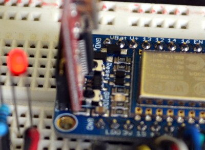
On a breadboard you’ll have two rows not covered by the board on one side, and one row on the other. The board doesn’t have a USB-to-UART bridge but we’re fine with that. On one end of the board you’ll find the common pinout for a USB-to-serial programming cable. Above you can see the programming cable Adafruit sent me with these samples. To the right I tried out my 5V Sparkfun FTDI board and as advertised, the HUZZAH can be programmed with either 3.3v or 5V logic levels.

The one thing I noticed is that the two buttons are a bit tricky to get at with the programmers connected, especially the FTDI board. For the second module I may supply my own right-angle header to get around that. Of course doing so would cover part of the breadboard so this is probably six of one, half dozen of the other.

I love it that they supply the pin headers but don’t solder them. Sometimes I prefer pin sockets or unpopulated pads, and this makes it easy for me to make that choice like the right-angle one I mentioned above. It’s something small but I also appreciate that the pinheaders in the package were not the minimum number necessary for this board — there were a few extra pins. You need to break them off and sometimes they can break one pin over from where you expected. If it were the minimum number you would either start over or solder a single pin at the end of the row (not ideal). If you screw up snapping these you could conceivably use a set of three pins and the rest as one unit to fix your mistake. Maybe I’m weird but it’s the small things in life!

Programming Options: NodeMCU and Lua

The board ships with this firmware on it. I was up and running with the Lua interpreter within three minutes of the package arriving at my door. Seriously, it took me longer to figure out if the USB-to-serial was green or white for TX/RX than it did to connect to my local WiFi Access point. Adafuit’s ‘Hello World’ walkthrough gets you going if you haven’t given this a try before.

Programming Options: Arduino IDE

Adafruit has a Board Manager for Arduino IDE. Perhaps this is common knowledge but I don’t often work with this IDE and it’s the first time I’ve run into it. What can I say, it kicks ass!
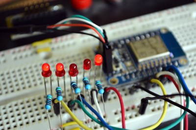
I hate setting up tool chains for new chips. With this you add a web address and port number, restart the IDE, and use the board manager to add support for this board. Sweet!

That turns this into an Arduino compatible board which solves something that has long bothered me. I’ve seen a ton of really simple Arduino projects that use the ESP8266 externally. Last month’s porting of the Arduino framework for these chips, coupled with this ready-to-go hardware does away with that nonsense. Seriously, the vast majority of those projects need little to no computing power and will work like a dream when directly programmed onto this chip.

To prove my point, I knocked out this quick binary counter that uses five LEDs as outputs. I’m not leveraging any of the WiFi features on this, but the compiled binary is 174,358 bytes and the Arduino IDE reports this board has a max capacity of 524,288 bytes. It five I/O used for LEDs there are still four more digital pins, the two UART pins, and an ADC input.

Programming Options: esptool

Arduino will overwrite NodeMCU but that’s easy to reflash. I followed [cnlohr’s] direct programming guide to write the binary using esptool. Both this method and the Arduino method are directly programming the EEPROM on the module. This is exactly the same method you’d use if you wanted to develop natively using the Espressif or the Open Source SDKs. Here’s the commands I used to reflash the NodeMCU firmware:

sudo python esptool.py --port /dev/ttyUSB0 write_flash 0x0000 /home/mike/Downloads/nodemcu_latest.bin

Get the NodeMCU binary from their “latest” folder of github repo.

Conclusion

“Buy as many of these as [Phil] will make for us.” That’s what I’ve asked [Julian], the Hackaday Store manager to do. You should be able to get the Hackaday black version of this in a few weeks. Adafruit is currently sold out but I’m sure they’re racing to remedy this.

These are amazing little boards. The price of $9.95 is crazy considering what you get for it. I’m talking about the entire ecosystem which gives you multiple flavors of programming environments. Adafruit has done a lot to contribute to the code and knowledge base here, but a mammoth portion of this is community developed and I think coming in low on the price is one more way Adafruit has chosen to be a good guy in this ecosystem. The board has a ton of I/O for what it is, and if that’s not enough just, implement I2C, SPI, or UART to couple a beefy uC to the connectivity this one brings to the party. I see zero downside on this board. It’s as close to perfect as you can get.


Filed under: Arduino Hacks, Hackaday Columns, reviews

Hackaday Links: April 12, 2015

Everyone loves Top Gear, or as it’s more commonly known, The Short, The Slow, And The Ugly. Yeah, terrible shame [Clarkson] ruined it for the rest of us. Good News! A show featuring drones will be filling the Top Gear timeslot. And on that bombshell…

More Arduino Drama! A few weeks ago, Arduino SRL (the new one) forked the Arduino IDE from Arduino LLC’s repo. The changes? The version number went up from 1.6.3 to 1.7. It’s been forked again, this time by [Mastro Gippo]. The changes? The version number went up to 2.0. We’re going to hold off until 2.1; major releases always have some bugs that take a few weeks to patch. Luckily the speed of the development cycle here means that patch should be out soon.

Need an ESP8266 connected to an Arduino. Arachnio has your back. Basically, it’s an Arduino Micro with an ESP8266 WiFi module. It also includes a Real Time Clock, a crypto module, and a solar battery charger. It’s available on Kickstarter, and we could think of a few sensor base station builds this would be useful for.

[Ben Heck] gave The Hacakday Prize a shoutout in this week’s episode. He says one of his life goals is to go to space. We’re giving that away to the project that makes the biggest difference for the world. We’re not sure how a [Bill Paxton] pinball machine fits into that category, but we also have a Best Product category for an opportunity to spend some time in a hackerspace… kind of like [Ben]’s 9 to 5 gig…

[Jim Tremblay] wrote a real time operating system for a bunch of different microcontrollers. There are a lot of examples for everything from an Arduino Mega to STM32 Discovery boards. Thanks [Alain] for the tip.

45s – the grammophone records that play at 45 RPM – are seven inches in diameter. Here’s one that’s 1.5 inches in diameter. Does it work? No one knows, because the creator can’t find a turntable to play it on.

Are we betting on the number of people who don’t get the joke in the first paragraph of this post? Decide in the comments.


Filed under: Hackaday Columns, Hackaday links

Hacklet 39: The Kerbal Way Of Doing Things

Kerbal Space Program is a space flight simulator based on an extremely stupid race of green space frogs that have decided to dedicate all their resources towards the exploration of space. It is a great game, a better space simulator than just about anything except for Orbiter, and the game is extremely moddable. For this edition of the Hacklet, we’re going to be taking a look at some of the mods for KSP you can find over on hackaday.io.

Like most hardware builds for Kerbal Space Program, [lawnmowerlatte] is using a few user-made plugins for KAPCOM, a hardware controller and display for KSP. The Telemachus plugin is used to pull data from the game and display that data on a few screens [lawnmower] had sitting around.

There are a few very cool features planned for this build including seven-segment displays, a throttle handle, and neat enclosure.


[Gabriel] is working on a similar build for KSP. Like the KAPCOM, this one uses the Telemachus plugin, but this one adds three eight-digit, SPI-controlled, seven-segment displays, relegendable buttons, and a Kerbal-insipired frame made out of Meccano.


[Lukas]’ KSP Control Panel is another complicated control system that breaks immersion slightly less than a keyboard. He’s using a Raspberry Pi to talk to the Telemachus server to control every aspect of the craft. From staging to opening up the solar panels, it’s all right there in [Lukas]’ control panel.


You may have noticed a theme with these builds; all of them use the Telemachus plugin for KSP. Even though it’s fairly simple to create plugins for Unity, there really aren’t that many KSP plugins build for these immersive control panels and space flight simulators. Or rather, Telemachus is ‘good enough’. We’d like to see a fully controllable KSP command pod model, just like those guys with 737 flight simulators in their garage. If you have any idea how that could happen, leave a note in the comments.


Filed under: Hackaday Columns

Hacklet 29 – Altoids Mint Tin Projects

Altoids – they’ve been around since King George III was on the throne. These curiously strong mints have had a storied history, a copy of which is included in every tin. They taste pretty good, but most hackers and makers are more interested in the pocket-sized tin than the mints themselves. It may have been the ham radio operators who first used Altoids tins to hold their sensitive transmitter and receiver circuits. The metal case makes a perfect electromagnetic field shield. It wasn’t long before the tins found their way into thousands of projects. This week’s Hacklet features some of the best projects with Altoids (and other mint) tins on Hackaday.io!

We start with [Chad Lawson] and the Networking Group Timing Light. [Chad] has a networking meeting where each member has two minutes to introduce themselves. As is the case with most meetings, people tend to be a bit long-winded, running well beyond their allotted two minutes. The timing light contains an RGB LED which changes from green to yellow to red as a speaker’s time ticks away. The timer is reset by simply tilting the mint tin. [Chad] is hoping that the timer will serve as a gentle reminder to keep everyone on track time-wise.


Next up is [Rjpope42] and his AM/FM Transmitter Pair. [Rjpope42] loves vintage tube radios, and wants to send his own signals to his amber glowing projects. Wiring an external audio input to a tube radio is pretty easy, but nothing beats a simple AM transmitter for convenience. Small FM transmitters are commonly available to add an MP3 player input to cars without an AUX audio in, but their AM counterparts have become rare. [Rjpope42] has built AM and FM transmitters, each of which will fit in a Mint Tin case. The AM transmitter can run on 9V or 12V, and even includes a USB power output for charging an MP3 player or phone!

[John Hamann] entered Distance Analyzer 3000 in the Trinket EDC contest. While he didn’t win, it was still a great project, especially since this is [John’s] first serious Arduino project. The idea is to use a rotary encoder with a wheel to measure distances. Think of it like a mini version of a surveyor’s walking wheel. The Pro Trinket counts the pulses from the rotary encoder, then converts this to a distance in feet. We’d love to see [John] continue on the project. An ultrasonic distance sensor would be a great addition for multi-sensor distance reads!


Finally, we have [colonwq] with TTTOTP, a pro trinket Time based One Time Password (TOTP) generator. [colonwq] used the trinket to implement the well-known time based one time password algorithm. To implement a project like this, you need a stable time source. The ATmega328 isn’t very good at this, so [colonwq] used a Dallas DS1307 clock chip to keep track of things. The actual code is displayed on a 4 digit 7 segment display. When the button is pressed, the first half of the code is displayed. Once the button is released, the second half of the code is displayed for several seconds.


Need more mint? Check out our curiously awesome mint tin project list!

Hackaday.io Update and MeArm Giveaway

Hackaday.io has a few new features, including @username and #projectID. If you mention someone’s username with an @ in front of it, that user will get a notification in their stack. The same goes with mentioning a project ID with a # up front. To celebrate this, we’re giving away a pair of  special edition MeArms. All you have to do is leave a comment using the features on this project log. Huge thanks to [Jasmine] for setting all this up, and to [Ben] for letting us hijack his project for the week!

That’s it for this Hacklet, As always, see you next week. Same hack time, same hack channel, bringing you the best of Hackaday.io!


Filed under: Hackaday Columns

Developed on Hackaday: Mooltipass Arduino Shields Compatibility

Some of our dear readers may already have an infallible system to remember different complex passwords for the different websites they visit daily. This is why they may have not been following the offline password keeper that the Hackaday community is building.

The Mooltipass has a characteristic that may regain their interest: it is possible to connect Arduino shields to it. In the video embedded below you can see the Arduino conversion process our development team imagined a few months back. The operation simply consists in using a knife to remove plastic bits on top of standard Arduino headers. We also embedded a few use cases with their respective sketches that may be downloaded from our official GitHub repository.

As with stacking several shields, a little tweaking may be required to keep the functionalities from both the Mooltipass and the connected shield. We therefore strongly welcome Arduino enthusiasts to let us know what they think of our setup.

In the meantime, you may want to subscribe to our official Google Group to stay informed of the Mooltipass launch date.


Filed under: Hackaday Columns

Sparkfun Ships 2000 MicroViews Without Bootloaders

Everyone has a bad day right? Monday was a particularly bad day for the folks at Sparkfun. Customer support tickets started piling up, leading to the discovery that they had shipped out as many as 1,934 MicroViews without bootloaders.

MicroView is the tiny OLED enabled, Arduino based, microcontroller system which had a wildly successful Kickstarter campaign earlier this year. [Marcus Schappi], the project creator, partnered up with SparkFun to get the MicroViews manufactured and shipped out to backers. This wasn’t a decision made on a whim, Sparkfun had proven themselves by fulfilling over 11,000 Makey Makey boards to backers of that campaign.

Rather than downplay the issue, Sparkfun CEO [Nathan Seidle] has taken to the company blog to explain what happened, how it happened, and what they’re going to do to make it right for their customers. This positions them as the subject of our Fail of the Week column where we commiserate instead of criticize.

First things first, anyone who receives an effected MicroView is getting a second working unit shipped out by the beginning of November. Furthermore, the bootloaderless units can be brought to life relatively easily. [Nate] provided a hex file with the correct bootloader. Anyone with an Atmel AVR In-System Programming (ISP) programmer and a steady hand can bring their MicroView to life. Several users have already done just that. The bootloader only has to be flashed via ISP once. After that, the MicroView will communicate via USB to a host PC. Sparkfun will publish a full tutorial in a few weeks.

Click past the break to read the rest of the story.

So what went wrong? The crux of the problem is a common one to manufacturing: An incomplete production test. For many of their products, Sparkfun loads a single hex file containing the production test and the optiboot bootloader. The test code proves out the functionality of the device, and the bootloader allows the customer to flash the device with their own sketches. The problem is the bootloader normally connects to a PC host via USB. Enumerating a USB connection can take up to 30 seconds. That’s way too slow for volume production.

Sparkfun opted to skip the bootloader test, since all the pins used to load firmware were electrically tested by their production test code. This has all worked fine for years – until now. The production team made a change to the test code on July 18th. The new hex file was released without the bootloader. The production test ran fine, and since no one was testing the bootloader, the problem wasn’t caught until it was out in the wild.

The Sparkfun crew are taking several steps to make sure this never happens again.They’re using a second ATmega chip on their test fixture to verify the bootloader without the slow PC enumeration step. Sparkfun will also avoid changing firmware during a production run. If firmware has to change, they’re planning to beta test before going live on the production line. Finally, Sparkfun is changing the way they approach large scale production. In [Nathan's] own words:

Moving from low volume to mid-volume production requires a very different approach. SparkFun has made this type of mistake before (faulty firmware on a device) but it was on a smaller scale and we were agile enough to fix the problem before it became too large. As we started producing very large production runs we did not realize quality control and testing would need very different thinking. This was a painful lesson to learn but these checks and balances are needed. If it didn’t happen on Microview it would have happened on a larger production run someday in the future.

Everyone has bad days, this isn’t the first time Sparkfun has lost money due to a mistake. However, they’re doing the right thing by attacking it head on and fixing not only the immediate issue but the underlying thought process which allowed the problem to arise.


Filed under: Hackaday Columns, news