Posts with «electronics» label

Kit Review – Jaycar “Short Circuits” 3 Digit Counter

Introduction

Time for another kit review and in this instalment we have a look at the “3 digit counter” kit from Jaycar. This is part of a much larger series of kits that are described in a three volume set of educational books from Jaycar titled “Short Circuits”.

Aimed at the younger readers or anyone who has an interest in learning electronics, these books (volumes one, two and three) are well written and with some study and practice the reader will make a large variety of projects and learn quite a bit. They could be considered as a worthy 21st-century replacement to the old Dick Smith “Funway…” guides.

The purpose of this kit is to give you a device which can count upwards between zero and 999 – which can be used for various purposes and also of course to learn about digital electronics.

Assembly

The kit arrives in typical retail fashion:

Everything you need to make the counter is included except for the instructions – which are found in the “Short Circuits” volume two book – and IC sockets. Kits for beginners with should come with IC sockets.

The components are separated neatly in the bag above, and it was interesting to see the use of zero ohm resistors for the two links on the board:

The PCB is excellent. The silk screening and solder-mask is very well done.

Furthermore I was really, really impressed with the level of detail with the drilling. The designer has allowed for components with different pin spacing – for example the 100 nF capacitor and transistors as shown below:

The instructions in the book are very clear and are written in an approachable fashion:

There’s also a detailed explanation on how the circuit works, some interesting BCD to decimal notes, examples of use (slot cars!) and a neat diagram showing how to mount the kit in a box using various parts from Jaycar – so you’re not left on your own.

Construction went well, starting with the low-profile parts:

… then the semiconductors:

… then the higher-profile parts and we’re finished:

There wasn’t any difficulty at all, and the counter worked first time. Although I’m not a new user, the quality of PCB and instructions would have been a contributing factor to the success of the kit.

How it works

The input signal for the counter (in this case a button controlling current from the supply rail) is “squared-up” by an MC14093 schmitt-trigger IC, which then feeds a MC14553 BCD counter IC, which counts and then feeds the results to a 4511 BCD to 7-segment converter to drive the LED digits which are multiplexed by the MC14553. For the schematic and details please refer to the book. Operation is simple, and demonstrated in the following video:

However you can feed the counter an external signal, by simply applying it to the input section of the circuit. After a quick modification:

… it was ready to be connected to a function generator. In the following video we send pulses with a varying frequency up to 2 kHz:

Conclusion

This is a neat kit, works well and with the accompanying book makes a good explanation of a popular digital electronics subject. There aren’t many good “electronics for beginners” books on the market any more, howevert the “Short Circuits” range from Jaycar really fit the bill.

So if you’re looking to learn more about electronics or start someone else off, head in to Jaycar and have a look. Readers from outside Australia are also covered. Full-sized images are available on flickr.

And while you’re here – are you interested in Arduino? Check out my new book “Arduino Workshop” from No Starch Press.

In the meanwhile have fun and keep checking into tronixstuff.com. Why not follow things on twitterGoogle+, subscribe  for email updates or RSS using the links on the right-hand column? And join our friendly Google Group – dedicated to the projects and related items on this website. Sign up – it’s free, helpful to each other –  and we can all learn something.

[Note – kit and book purchased without notifying the supplier]

The post Kit Review – Jaycar “Short Circuits” 3 Digit Counter appeared first on tronixstuff.

Tronixstuff 04 Dec 22:00

Low-cost Arduino-compatible electronics kit

There is an Indiegogo campaign to sell a kit for learning electronics that seems to have better pricing than most of the similar kits I’ve seen: BE MAKER! KIT plus FREE lessons on electronics, from Zero to Internet of Things | Indiegogo.

The most popular product they are selling seems to be a $69 kit with a microprocessor board (a clone of the Arduino Leonardo); a “shield” with an LCD display driver, pushbuttons, microSD card reader, 2 servo connections, RGB LED strip driver, and Ethernet adapter; a bunch of useful electronics parts (including an LCD display for the shield and an RGB LED strip); “lessons” (which are probably just assembly instructions for different projects, but may be more tutorial) and a box to keep all the tiny parts in.

As Arduino and Arduino-compatible kits go, this one looks pretty good.  Forget about it for holiday gift-giving though, as they don’t expect to deliver until February 2014.  If you want something similar for this year, look at the somewhat more expensive kits from AdaFruit or SparkFun.


Filed under: Uncategorized Tagged: Adafruit Industries, Arduino, education, electronics, Indiegogo, SparkFun Electronics

Old Kit Review – Silicon Chip Mini Stereo Amplifier

Introduction

In this review of an older kit we examine the aptly-named “Mini Stereo Amplifier” from Dick Smith Electronics (catalogue number K5008), based on the article published in the October 1992 issue of Silicon Chip magazine.

The purpose of the kit is to offer a stereo 1W+1W RMS amplifier for use with portable audio devices that only used headphones, such as the typical portable tape players or newly available portable CD players. I feel old just writing that. At the time it would have been quite a useful kit, paired with some inexpensive speakers the end user would have a neat and portable sound solution. So let’s get started.

Assembly

Larger kits like this one that couldn’t be retailed on hanger cards shipped in corrugated cardboard boxes that were glued shut. They looked good but as soon as a sneaky customer tore one open “to have a look” it was ruined and hard to sell:

The amplifier kit was from the time when DSE still cared about kits, so you received the sixteen page “Guide to Kit Construction” plus the kit instructions, nasty red disclaimer sheet, feedback card, plus all the required components and the obligatory coil of solder that was usually rubbish:

However the completeness of the kit is outstanding, everything is included for completion including an enclosure and handy front panel sticker:

… all the sockets, plenty of jumper wire and even the rubber feet:

The PCB is from the old-school of design – without any silk-screening or solder mask:

However the instructions are quite clear so you can figure out the component placement easily. Which brings us to that point – all the components went in with ease:

… then it was a matter of wiring in the sockets, volume potentiometer and power switch:

Instead of using a 3.5mm phono socket for power input, I used a 9V battery snap instead. The amplifier can run on voltages down to 1.8V so it will do for the limited use I have in mind for the amplifier. However in the excitement of assembly I forgot the power switch:

However it wasn’t any effort to rectify that. You will also notice three links on the PCB, which I fitted instead of making coils (more on this later). So at that point the soldering work is finished:

Now to drill out the holes on the faceplate. Instead of tapering out the slots on the side of the housing, I just drilled all the holes on the front panel:

Turns out the adhesive on the front panel sticker had lost its mojo, so I might head off and get some white-on-black tape for the label maker. However in the meanwhile we have one finished mini stereo amplifier, which reminds me of an old grade seven electronics project:

How it works

The amplifier is based on the STMicro TDA2822M (data sheet .pdf) dual low-voltage amplifier IC. In fact the circuit is a slight modification of the stereo example in the data sheet. As mentioned earlier, the benefit of this IC is that it can operate on voltates down to 1.8V, however to reach the maximum power output of 1W per channel into 8Ω loads you need a 9V supply. The output will drop to around 300 mW at 6V.

Finally the Silicon Chip design calls for a triplet of coils, one each on the stereo input wires – used to prevent the RF signal being “shunted away” from the amplifier inputs. The idea behind that was some portable radios used the headphones as an antenna, however we’ll use it with the audio out from a mobile phone so it was easier to skip hand-winding the coils and just put links in the PCB.

Using the Amplifier

The purpose of this kit was to have some sound while working in the garage, so I’ve fitted a pair of cheap 1W 8Ω speakers each to a length of wire and a 3.5mm plug as shown in the image above. And for that purpose, it works very well. In hindsight it turns out the speakers were rated at 1W peak not RMS, however they still sound great.

Conclusion

Another kit review over. This is a genuinely useful kit and a real shame you can’t buy one today. And again – to those who have been asking me privately, no I don’t have a secret line to some underground warehouse of old kits – just keep an eye out on ebay as they pop up now and again. Full-sized images and much more information about the kit are available on flickr.

And while you’re here – are you interested in Arduino? Check out my new book “Arduino Workshop” from No Starch Press.

In the meanwhile have fun and keep checking into tronixstuff.com. Why not follow things on twitterGoogle+, subscribe  for email updates or RSS using the links on the right-hand column? And join our friendly Google Group – dedicated to the projects and related items on this website. Sign up – it’s free, helpful to each other –  and we can all learn something.

The post Old Kit Review – Silicon Chip Mini Stereo Amplifier appeared first on tronixstuff.

Tronixstuff 21 Nov 23:33

Kit Review – Altronics 3 Digit Counter Module

Introduction

In this review we examine the three digit counter module kit from Altronics. The purpose of this kit is to allow you to … count things. You feed it a pulse, which it counts on the rising edge of the signal. You can have it count up or down, and each kit includes three digits.

You can add more digits, in groups of three with a maximum of thirty digits. Plus it’s based on simple digital electronics (no microcontrollers here) so there’s some learning afoot as well. Designed by Graham Cattley the kit was first described in the now-defunct (thanks Graham) January 1998 issue of Electronics Australia magazine.

Assembly

The kit arrives in the typical retail fashion:

And includes the magazine article reprint along with Altronics’ “electronics reference sheet” which covers many useful topics such as resistor colour codes, various formulae, PCB track widths, pinouts and more. There is also a small addendum which uses two extra (and included) diodes for input protection on the clock signal:

The counter is ideally designed to be mounted inside an enclosure of your own choosing, so everything required to build a working counter is included however that’s it:

No IC sockets, however I decided to live dangerously and not use them – the ICs are common and easily found. The PCBs have a good solder mask and silk screen:

With four PCBs (one each for a digit control and one for the displays) the best way to start was to get the common parts out of the way and fitted, such as the current-limiting resistors, links, ICs, capacitors and the display module. The supplied current-limiting resistors are for use with a 9V DC supply, however details for other values are provided in the instructions:

At this point you put one of the control boards aside, and then start fitting the other two to the display board. This involves holding the two at ninety degrees then soldering the PCB pads to the SIL pins on the back of the display board. Starting with the control board for the hundreds digit first:

… at this stage you can power the board for a quick test:

… then fit the other control board for the tens digit and repeat:

Now it’s time to work with the third control board. This one looks after the one’s column and also a few features of the board. Several functions such as display blanking, latch (freeze the display while still counting) and gate (start or stop counting) can be controlled and require resistors fitted to this board which are detailed in the instructions.

Finally, several lengths of wire (included) are soldered to this board so that they can run through the other two to carry signals such as 5V, GND, latch, reset, gate and so on:

These wires can then be pulled through and soldered to the matching pads once the last board has been soldered to the display board:

 You also need to run separate wires between the carry-out and clock-in pins between the digit control boards (the curved ones between the PCBs):

For real-life use you also need some robust connections for the power, clock, reset lines, etc., however for demonstration use I just used alligator clips. Once completed a quick power-up showed the LEDs all working:

How it works

Each digit is driven by a common IC pairing – the  4029 (data sheet) is a presettable up/down counter with a BCD (binary-coded decimal) output which feeds a 4511 (data sheet) that converts the BCD signal into outputs for a 7-segment LED display. You can count at any readable speed, and I threw a 2 kHz square-wave at the counter and it didn’t miss a beat. By default the units count upwards, however by setting one pin on the board LOW you can count downwards.

Operation

Using the counters is a simple matter of connecting power, the signal to count and deciding upon display blanking and the direction of counting. Here’s a quick video of counting up, and here it is counting back down.

Conclusion

This is a neat kit that can be used to count pulses from almost anything. Although some care needs to be taken when soldering, this isn’t anything that cannot be overcome without a little patience and diligence. So if you need to count something, get one ore more of these kits from Altronics. Full-sized images are available on flickr. And while you’re here – are you interested in Arduino? Check out my new book “Arduino Workshop” from No Starch Press – also shortly available from Altronics.

In the meanwhile have fun and keep checking into tronixstuff.com. Why not follow things on twitterGoogle+, subscribe  for email updates or RSS using the links on the right-hand column? And join our friendly Google Group – dedicated to the projects and related items on this website. Sign up – it’s free, helpful to each other –  and we can all learn something.

The post Kit Review – Altronics 3 Digit Counter Module appeared first on tronixstuff.

Tronixstuff 18 Nov 06:55

Old Kit Review – Diesel Sound Simulator for Model Railroads

Introduction

In this review of an older kit (circa 1993~1997) we examine the Diesel Sound Simulator for Model Railroads kit from (the now defunct) Dick Smith Electronics, based on the article published in the December 1992 issue of Silicon Chip magazine.

The purpose of this kit is to give you a small circuit which can fit in a HO scale (or larger) locomotive, or hidden underneath the layout – that can emulate the rumbling of a diesel-electric locomotive to increase the realism of a train. However the kit is designed for use with a PWM train controller (also devised by Silicon Chip!) so not for the simple direct-DC drive layouts.

Assembly

The diesel sound kit was from the time when DSE still cared about kits, so you received the sixteen page “Guide to Kit Construction” plus the kit instructions, nasty red disclaimer sheet, feedback card, plus all the required components and the obligatory coil of solder that was usually rubbish:

Everything required to get going is included, except IC sockets. My theory is it’s cheaper to use your own sockets than source older CMOS/TTL later on if you want to reuse the ICs, so sockets are now mandatory here:

The PCB is from the old school of “figure-it-out-yourself”, no fancy silk-screening here:

Notice the five horizontal pads between the two ICs – these were for wire bridges in case you needed to break the PCB in two to fit inside your locomotive.

Actual assembly was straight-forward, all the components went in without any issues. Having two links under IC2 was a little annoying, however a short while later the PCB was finished and the speaker attached:

How it works

As mentioned earlier this diesel sound kit was designed for use with the Silicon Chip train PWM controller, so the design is a little different than expected. It can handle a voltage of around 20 V, and the sound is determined by the speed of the locomotive.

The speed is determined by the back EMF measured from the motor – and (from the manual) this is the voltage produced by the motor which opposes the current flow through it and this voltage is directly proportional to speed.

Not having a 20V DC PWM supply laying about I knocked up an Arduino to PWM a 20V DC supply via an N-MOSFET module and experimented with the duty cycle to see what sort of noises could be possible. The output was affected somewhat by the supply voltage, however seemed a little higher in pitch than expected.

You can listen to the results in the following video:

I reckon the sound from around the twenty second mark isn’t a bad idle noise, however in general not that great. The results will ultimately be a function of a lower duty-cycle than I could create at the time and the values of R1 and R2 used in the kit.

 Conclusion

Another kit review over. With some time spent experimenting you could generate the required diesel sounds, a Paxman-Valenta it isn’t… but it was a fun kit and I’m sure it was well-received at the time. To those who have been asking me privately, no I don’t have a secret line to some underground warehouse of old kits – just keep an eye out on ebay and they pop up now and again. Full-sized images and much more information about the kit are available on flickr.

And while you’re here – are you interested in Arduino? Check out my new book “Arduino Workshop” from No Starch Press.

In the meanwhile have fun and keep checking into tronixstuff.com. Why not follow things on twitterGoogle+, subscribe  for email updates or RSS using the links on the right-hand column? And join our friendly Google Group – dedicated to the projects and related items on this website. Sign up – it’s free, helpful to each other –  and we can all learn something.

The post Old Kit Review – Diesel Sound Simulator for Model Railroads appeared first on tronixstuff.

Tronixstuff 10 Nov 08:12

Tutorial – LM3914 Dot/Bar Display Driver IC

Introduction

This is the first of three tutorials that will examine the LM391x series of LED driver ICs. In this first tutorial we cover the LM3914, then the LM3915 and LM3916 will follow. The goal of these tutorials is to have you using the parts in a small amount of time and experiment with your driver ICs, from which point you can research further into their theory and application.

Although these parts have been around for many years, the LM3914 in particular is still quite popular. It offers a simple way to display a linear voltage level using one or more groups of ten LEDs with a minimum of fuss.

With a variety of external parts or circuitry these LEDs can then represent all sorts of data, or just blink for your amusement. We’ll run through a few example circuits that you can use in your own projects and hopefully give you some ideas for the future. Originally by National Semiconductor, the LM391X series is now handled by Texas Instruments.

Getting Started

You will need the LM3914 data sheet, so please download that and keep it as a reference. So – back to basics. The LM3914 controls ten LEDs. It controls the current through the LEDs with the use of only one resistor, and the LEDs can appear in a bar graph or single ‘dot’ when in use. The LM3914 contains a ten-stage voltage divider, each stage when reached will illuminate the matching LED (and those below it in level meter mode).

Let’s consider the most basic of examples (from page two of the data sheet) – a voltmeter with a range of 0~5V:


The Vled rail is also connected to the supply voltage in our example. Pin 9 controls the bar/dot display mode – with it connected to pin 3 the LEDs will operate in bar graph mode, leave it open for dot mode. The 2.2uF capacitor is required only when “leads to the LED supply are 6″ or longer”. We’ve hooked up the circuit above, and created a 0~5V DC source via a 10kΩ potentiometer with a multimeter to show the voltage – in the following video you can see the results of this circuit in action, in both dot and bar graph mode:

Customising the upper range and LED current

Well that was exciting, however what if you want a different reference voltage? That is you want your display to have a range of 0~3 V DC? And how do you control the current flow through each LED? With maths and resistors. Consider the following formulae:

As you can see the LED current (Iled) is simple, our example is 12.5/1210 which returned 10.3 mA – and in real life 12.7 mA (resistor tolerance is going to affect the value of the calculations).

Now to calculate a new Ref Out voltage – for example  we’ll shoot for a 3 V meter, and keep the same current for the LEDs. This requires solving for R2 in the equation above, which results with R2 = -R1 + 0.8R1V. Substituting the values – R2 = -1210 + 0.8 x 1210 x 3 gives a value of 1694Ω for R2. Not everyone will have the E48 resistor range, so try and get something as close as possible. We found a 1.8 kΩ for R2 and show the results in the following video:

You can of course have larger display range values, but a supply voltage of no more than 25 V will need to be equal to or greater than that value. E.g. if you want a 0~10 V display, the supply voltage must be >= 10V DC.

Creating custom ranges

Now we’ll look at how to create  a lower range limit, so you can have displays that (for example) can range from a non-zero positive value. For example, you want to display levels between 3 and 5V DC. From the previous section, you know how to set the upper limit, and setting the lower limit is simple – just apply the lower voltage to pin 4 (Rlo).

You can derive this using a resistor divider or other form of supply with a common GND. When creating such circuits, remember that the tolerance of the resistors used in the voltage dividers will have an affect on the accuracy. Some may wish to fit trimpots, which after alignment can be set permanently with a blob of glue.

Finally, for more reading on this topic – download and review the TI application note.

Chaining multiple LM3914s

Two or more LM3914s can be chained together to increase the number of LEDs used to display the levels over an expanded range. The circuitry is similar to using two independent units, except the REFout (pin 7) from the first LM3914 is fed to the REFlo (pin 4) of the second LM3914 – whose REFout is set as required for the upper range limit. Consider the following example schematic which gave a real-world range of 0~3.8V DC:

The 20~22kΩ resistor is required if you’re using dot mode (see “Dot mode carry” in page ten of the data sheet). Moving on, the circuit above results with the following:

Where to from here?

Now you can visually represent all sorts of low voltages for many purposes. There’s more example circuits and notes in the LM3914 data sheet, so have a read through and delve deeper into the operation of the LM3914. Furthermore Dave Jones from eevblog.com has made a great video whcih describes a practical application of the LM3914:

Conclusion

As always I hope you found this useful. Don’t forget to stay tuned for the second and third instalments using the LM3915 and LM3916. Full-sized images are on flickr. And if you made it this far – check out my new book “Arduino Workshop” from No Starch Press.

In the meanwhile have fun and keep checking into tronixstuff.com. Why not follow things on twitterGoogle+, subscribe  for email updates or RSS using the links on the right-hand column? And join our friendly Google Group – dedicated to the projects and related items on this website. Sign up – it’s free, helpful to each other –  and we can all learn something.

The post Tutorial – LM3914 Dot/Bar Display Driver IC appeared first on tronixstuff.

Tronixstuff 13 Sep 15:13
bar  display  dot  driver  electronics  example  ic  led  level  lm3914  lm3915  lm3916  ti  tronixstuff  tutorial  voltmeter  

Australian Electronics Nostalgia – Talking Electronics Kits

Introduction

From 1981, Australian electrical engineer Colin Mitchell started publishing his home-grown electronics magazine “Talking Electronics”. His goal was to get people interested and learning about electronics, and more so with a focus on digital electronics. It was (and still is) a lofty goal – in which he succeeded. From a couple of rooms in his home the magazine flourished, and many projects described within were sold as kits. At one stage there were over 150 Talking Electronics kits on the market. You could find the books and kits in retail outlets such as Dick Smith Electronics, and for a short while there was a TE store in Moorabbin (Victoria). Colin and the team’s style of writing was easy to read and very understandable – but don’t take my word for it, you can download the magazines from his website (they’re near the bottom of the left column). Dave Jones recently interviewed Colin, and you can watch those for much more background information.

Over fifteen issues you could learn about blinking LEDs all the way to making your own expandable Z80 board computer, and some of the kits may still be available. Colin also published a series of tutorial books on electronics, and also single-magazine projects. And thus the subjects of our review … we came across the first of these single-issue projects from 1981 – the Mini Frequency Counter (then afterwards we have another kit):

How great is that? The PCB comes with the magazine. This is what set TE apart from the rest, and helped people learn by actually making it easy to build what was described in the magazine instead of just reading about it. For 1981 the PCB was quite good – they were silk-screened which was quite rare at the time:

And if you weren’t quite ready, the magazine also included details of a square-wave oscillator to make and a 52-page short course in digital electronics. However back to the kit…

Assembly

The kit uses common parts and I hoard CMOS ICs so building wasn’t a problem. This (original) version of the kit used LEDs instead of 7-segment displays (which were expensive at the time) so there was plenty of  careful soldering to do:

And after a while the counter started to come together. I used IC sockets just in case:

The rest was straight-forward, and before long 9 V was supplied, and we found success:

To be honest progress floundered for about an hour at this point – the display wouldn’t budge off zero. After checking the multi-vibrator output, calibrating the RC circuits and finally tracing out the circuit with a continuity tester, it turned out one of the links just wasn’t soldered in far enough – and the IC socket for the 4047 was broken So a new link and directly fitting the 4047 fixed it. You live and learn.

Operation

So – we now have a frequency counter that’s good for 100 Hz to the megahertz range, with a minimum of parts. Younger, non-microcontroller people may wonder how that is possible – so here’s the schematic:

The counter works by using a multi-vibrator using a CD4047 to generate a square-wave at 50, 500 and 5 kHz, and the three trimpots are adjusted to calibrate the output. The incoming pulses to measure are fed to the 4026 decade counter/divider ICs. Three of these operate in tandem and each divide the incoming count by ten – and display or reset by the alternating signal from the 4047. However for larger frequencies (above 900 Hz) you need to change the frequency fed to the display circuit in order to display the higher (left-most) digits of the result. A jumper wire is used to select the required level (however if you mounted the kit in a case, a knob or switch could be used).

For example, if you’re measuring 3.456 MHz you start with the jumper on H and the display reads 345 – then you switch to M to read 456 – then you switch to the L jumper and read 560, giving you 3456000 Hz. If desired, you can extend the kit with another PCB to create a 5-digit display. The counter won’t be winning any precision contests – however it has two purposes, which are fulfilled very well. It gives the reader an inexpensive piece of test equipment that works reasonably well, and a fully-documented project so the reader can understand how it works (and more).

And for the curious –  here it is in action:

[Update 20/07/2013] Siren Kit

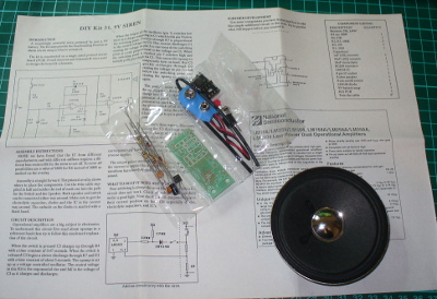
Found another kit last week, the Talking Electronics “DIY Kit #31 – 9V siren”. It’s an effective and loud siren with true rise and fall, unlike other kits of the era that alternated between two fixed tones. The packaging was quite strong and idea for mail-order at the time:

The label sells the product (and shows the age):

The kit included every part required to work, apart from a PP3 battery, and a single instruction sheet with a good explanation of how the circuit works, and some data about the LM358:

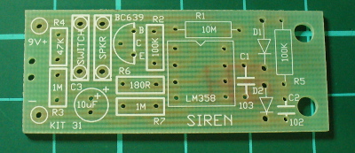
… and as usual the PCB was ahead of its’ time with full silk-screen and solder mask:

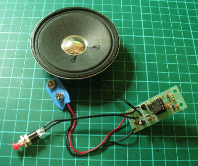
Assembly was quite straight-forward. The design is quite compact, so a lot of vertical resistor mounting was necessary due to the lack of space. However it was refreshing to not have any links to fit. After around twenty minutes of relaxed construction, it was ready to test:

It’s a 1/2 watt speaker, however much louder than originally anticipated:

Once again, another complete and well-produced kit.

Conclusion

That was a lot of fun, and I’m off to make the matching square-wave oscillator for the frequency counter. Kudos to Colin for all those years of publication and helping people learn. Lots of companies bang on about offering tutorials and information on the Internet for free, but Colin has been doing it for over ten years. Check out his Talking Electronics website for a huge variety of knowledge, an excellent electronics course you can get on CD – and go easy on him if you have any questions.

Full-sized images available on flickr. This kit was purchased without notifying the supplier.

And if you made it this far – check out my new book “Arduino Workshop” from No Starch Press.

In the meanwhile have fun and keep checking into tronixstuff.com. Why not follow things on twitterGoogle+, subscribe  for email updates or RSS using the links on the right-hand column? And join our friendly Google Group – dedicated to the projects and related items on this website. Sign up – it’s free, helpful to each other –  and we can all learn something.

The post Australian Electronics Nostalgia – Talking Electronics Kits appeared first on tronixstuff.

Tutorial – Arduino and PCF8591 ADC DAC IC

Learn how to use the NXP PCF 8591 8-bit A/D and D/A IC with Arduino in chapter fifty-two of my Arduino Tutorials. The first chapter is here, the complete series is detailed here.

Updated 17/06/2013

Introduction

Have you ever wanted more analogue input pins on your Arduino project, but not wanted to fork out for a Mega? Or would you like to generate analogue signals? Then check out the subject of our tutorial – the NXP PCF8591 IC. It solves both these problems as it has a single DAC (digital to analogue) converter as well as four ADCs (analogue to digital converters) – all accessible via the I2C bus. If the I2C bus is new to you, please familiarise yourself with the readings here before moving forward.

The PCF8591 is available in DIP form, which makes it easy to experiment with:
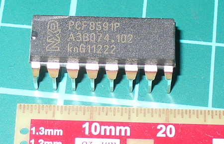
You can get them from the usual retailers. Before moving on, download the data sheet. The PCF8591 can operate on both 5V and 3.3V so if you’re using an Arduino Due, Raspberry Pi or other 3.3 V development board you’re fine. Now we’ll first explain the DAC, then the ADCs.

Using the DAC (digital-to-analogue converter)

The DAC on the PCF8591 has a resolution of 8-bits – so it can generate a theoretical signal of between zero volts and the reference voltage (Vref) in 255 steps. For demonstration purposes we’ll use a Vref of 5V, and you can use a lower Vref such as 3.3V or whatever you wish the maximum value to be … however it must be less than the supply voltage. Note that when there is a load on the analogue output (a real-world situation), the maximum output voltage will drop – the data sheet (which you downloaded) shows a 10% drop for a 10kΩ load. Now for our demonstration circuit:
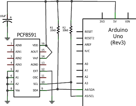
Note the use of 10kΩ pull-up resistors on the I2C bus, and the 10μF capacitor between 5V and GND. The I2C bus address is set by a combination of pins A0~A2, and with them all to GND the address is 0x90. The analogue output can be taken from pin 15 (and there’s a seperate analogue GND on pin 13. Also, connect pin 13 to GND, and circuit GND to Arduino GND.

To control the DAC we need to send two bytes of data. The first is the control byte, which simply activates the DAC and is 1000000 (or 0x40) and the next byte is the value between 0 and 255 (the output level). This is demonstrated in the following sketch:

// Example 52.1 PCF8591 DAC demo
// http://tronixstuff.com/tutorials Chapter 52
// John Boxall June 2013
#include "Wire.h"
#define PCF8591 (0x90 >> 1) // I2C bus address
void setup()
{
 Wire.begin();
}
void loop()
{
 for (int i=0; i<256; i++)
 {
 Wire.beginTransmission(PCF8591); // wake up PCF8591
 Wire.write(0x40); // control byte - turn on DAC (binary 1000000)
 Wire.write(i); // value to send to DAC
 Wire.endTransmission(); // end tranmission
 }

 for (int i=255; i>=0; --i)
 {
 Wire.beginTransmission(PCF8591); // wake up PCF8591
 Wire.write(0x40); // control byte - turn on DAC (binary 1000000)
 Wire.write(i); // value to send to DAC
 Wire.endTransmission(); // end tranmission
 }
}

Did you notice the bit shift of the bus address in the #define statement? Arduino sends 7-bit addresses but the PCF8591 wants an 8-bit, so we shift the byte over by one bit. 

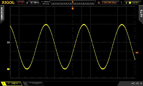
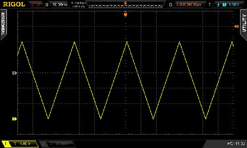
The results of the sketch are shown below, we’ve connected the Vref to 5V and the oscilloscope probe and GND to the analogue output and GND respectively:
If you like curves you can generate sine waves with the sketch below. It uses a lookup table in an array which contains the necessary pre-calculated data points:

// Example 52.2 PCF8591 DAC demo - sine wave
// http://tronixstuff.com/tutorials Chapter 52
// John Boxall June 2013

#include "Wire.h"
#define PCF8591 (0x90 >> 1) // I2C bus address

uint8_t sine_wave[256] = {
 0x80, 0x83, 0x86, 0x89, 0x8C, 0x90, 0x93, 0x96,
 0x99, 0x9C, 0x9F, 0xA2, 0xA5, 0xA8, 0xAB, 0xAE,
 0xB1, 0xB3, 0xB6, 0xB9, 0xBC, 0xBF, 0xC1, 0xC4,
 0xC7, 0xC9, 0xCC, 0xCE, 0xD1, 0xD3, 0xD5, 0xD8,
 0xDA, 0xDC, 0xDE, 0xE0, 0xE2, 0xE4, 0xE6, 0xE8,
 0xEA, 0xEB, 0xED, 0xEF, 0xF0, 0xF1, 0xF3, 0xF4,
 0xF5, 0xF6, 0xF8, 0xF9, 0xFA, 0xFA, 0xFB, 0xFC,
 0xFD, 0xFD, 0xFE, 0xFE, 0xFE, 0xFF, 0xFF, 0xFF,
 0xFF, 0xFF, 0xFF, 0xFF, 0xFE, 0xFE, 0xFE, 0xFD,
 0xFD, 0xFC, 0xFB, 0xFA, 0xFA, 0xF9, 0xF8, 0xF6,
 0xF5, 0xF4, 0xF3, 0xF1, 0xF0, 0xEF, 0xED, 0xEB,
 0xEA, 0xE8, 0xE6, 0xE4, 0xE2, 0xE0, 0xDE, 0xDC,
 0xDA, 0xD8, 0xD5, 0xD3, 0xD1, 0xCE, 0xCC, 0xC9,
 0xC7, 0xC4, 0xC1, 0xBF, 0xBC, 0xB9, 0xB6, 0xB3,
 0xB1, 0xAE, 0xAB, 0xA8, 0xA5, 0xA2, 0x9F, 0x9C,
 0x99, 0x96, 0x93, 0x90, 0x8C, 0x89, 0x86, 0x83,
 0x80, 0x7D, 0x7A, 0x77, 0x74, 0x70, 0x6D, 0x6A,
 0x67, 0x64, 0x61, 0x5E, 0x5B, 0x58, 0x55, 0x52,
 0x4F, 0x4D, 0x4A, 0x47, 0x44, 0x41, 0x3F, 0x3C,
 0x39, 0x37, 0x34, 0x32, 0x2F, 0x2D, 0x2B, 0x28,
 0x26, 0x24, 0x22, 0x20, 0x1E, 0x1C, 0x1A, 0x18,
 0x16, 0x15, 0x13, 0x11, 0x10, 0x0F, 0x0D, 0x0C,
 0x0B, 0x0A, 0x08, 0x07, 0x06, 0x06, 0x05, 0x04,
 0x03, 0x03, 0x02, 0x02, 0x02, 0x01, 0x01, 0x01,
 0x01, 0x01, 0x01, 0x01, 0x02, 0x02, 0x02, 0x03,
 0x03, 0x04, 0x05, 0x06, 0x06, 0x07, 0x08, 0x0A,
 0x0B, 0x0C, 0x0D, 0x0F, 0x10, 0x11, 0x13, 0x15,
 0x16, 0x18, 0x1A, 0x1C, 0x1E, 0x20, 0x22, 0x24,
 0x26, 0x28, 0x2B, 0x2D, 0x2F, 0x32, 0x34, 0x37,
 0x39, 0x3C, 0x3F, 0x41, 0x44, 0x47, 0x4A, 0x4D,
 0x4F, 0x52, 0x55, 0x58, 0x5B, 0x5E, 0x61, 0x64,
 0x67, 0x6A, 0x6D, 0x70, 0x74, 0x77, 0x7A, 0x7D
};
void setup()
{
 Wire.begin();
}
void loop()
{
 for (int i=0; i<256; i++)
 {
 Wire.beginTransmission(PCF8591); // wake up PCF8591
 Wire.write(0x40); // control byte - turn on DAC (binary 1000000)
 Wire.write(sine_wave[i]); // value to send to DAC
 Wire.endTransmission(); // end tranmission
 }
}

And the results:

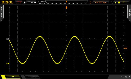
For the following DSO image dump, we changed the Vref to 3.3V – note the change in the maxima on the sine wave:
Now you can experiment with the DAC to make sound effects, signals or control other analogue circuits.

Using the ADCs (analogue-to-digital converters)

If you’ve used the analogRead() function on your Arduino (way back in Chapter One) then you’re already familiar with an ADC. With out PCF8591 we can read a voltage between zero and the Vref and it will return a value of between zero and 255 which is directly proportional to zero and the Vref. For example, measuring 3.3V should return 168. The resolution (8-bit) of the ADC is lower than the onboard Arduino (10-bit) however the PCF8591 can do something the Arduino’s ADC cannot. But we’ll get to that in a moment.

First, to simply read the values of each ADC pin we send a control byte to tell the PCF8591 which ADC we want to read. For ADCs zero to three the control byte is 0x00, 0x01, ox02 and 0x03 respectively. Then we ask for two bytes of data back from the ADC, and store the second byte for use. Why two bytes? The PCF8591 returns the previously measured value first – then the current byte. (See Figure 8 in the data sheet). Finally, if you’re not using all the ADC pins, connect the unused ones to GND.

The following example sketch simply retrieves values from each ADC pin one at a time, then displays them in the serial monitor:

// Example 52.3 PCF8591 ADC demo
// http://tronixstuff.com/tutorials Chapter 52
// John Boxall June 2013
#include "Wire.h"
#define PCF8591 (0x90 >> 1) // I2C bus address
#define ADC0 0x00 // control bytes for reading individual ADCs
#define ADC1 0x01
#define ADC2 0x02
#define ADC3 0x03
byte value0, value1, value2, value3;
void setup()
{
 Wire.begin();
 Serial.begin(9600);
}
void loop()
{
 Wire.beginTransmission(PCF8591); // wake up PCF8591
 Wire.write(ADC0); // control byte - read ADC0
 Wire.endTransmission(); // end tranmission
 Wire.requestFrom(PCF8591, 2);
 value0=Wire.read();
 value0=Wire.read();
 Wire.beginTransmission(PCF8591); // wake up PCF8591
 Wire.write(ADC1); // control byte - read ADC1
 Wire.endTransmission(); // end tranmission
 Wire.requestFrom(PCF8591, 2);
 value1=Wire.read();
 value1=Wire.read();
 Wire.beginTransmission(PCF8591); // wake up PCF8591
 Wire.write(ADC2); // control byte - read ADC2
 Wire.endTransmission(); // end tranmission
 Wire.requestFrom(PCF8591, 2);
 value2=Wire.read();
 value2=Wire.read();
 Wire.beginTransmission(PCF8591); // wake up PCF8591
 Wire.write(ADC3); // control byte - read ADC3
 Wire.endTransmission(); // end tranmission
 Wire.requestFrom(PCF8591, 2);
 value3=Wire.read();
 value3=Wire.read();
 Serial.print(value0); Serial.print(" ");
 Serial.print(value1); Serial.print(" ");
 Serial.print(value2); Serial.print(" ");
 Serial.print(value3); Serial.print(" ");
 Serial.println();
}

Upon running the sketch you’ll be presented with the values of each ADC in the serial monitor. Although it was a simple demonstration to show you how to individually read each ADC, it is a cumbersome method of getting more than one byte at a time from a particular ADC.

To do this, change the control byte to request auto-increment, which is done by setting bit 2 of the control byte to 1. So to start from ADC0 we use a new control byte of binary 00000100 or hexadecimal 0x04. Then request five bytes of data (once again we ignore the first byte) which will cause the PCF8591 to return all values in one chain of bytes. This process is demonstrated in the following sketch:

// Example 52.4 PCF8591 ADC demo
// http://tronixstuff.com/tutorials Chapter 52
// John Boxall June 2013
#include "Wire.h"
#define PCF8591 (0x90 >> 1) // I2C bus address
byte value0, value1, value2, value3;
void setup()
{
 Wire.begin();
 Serial.begin(9600);
}
void loop()
{
 Wire.beginTransmission(PCF8591); // wake up PCF8591
 Wire.write(0x04); // control byte - read ADC0 then auto-increment
 Wire.endTransmission(); // end tranmission
 Wire.requestFrom(PCF8591, 5);
 value0=Wire.read();
 value0=Wire.read();
 value1=Wire.read();
 value2=Wire.read();
 value3=Wire.read();
 Serial.print(value0); Serial.print(" ");
 Serial.print(value1); Serial.print(" ");
 Serial.print(value2); Serial.print(" ");
 Serial.print(value3); Serial.print(" ");
 Serial.println();
}

Previously we mentioned that the PCF8591 can do something that the Arduino’s ADC cannot, and this is offer a differential ADC. As opposed to the Arduino’s single-ended (i.e. it returns the difference between the positive signal voltage and GND, the differential ADC accepts two signals (that don’t necessarily have to be referenced to ground), and returns the difference between the two signals. This can be convenient for measuring small changes in voltages for load cells and so on.

Setting up the PCF8591 for differential ADC is a simple matter of changing the control byte. If you turn to page seven of the data sheet, then consider the different types of analogue input programming. Previously we used mode ’00’ for four inputs, however you can select the others which are clearly illustrated, for example:
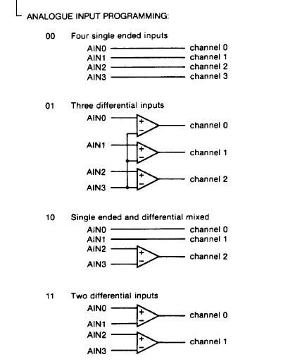
So to set the control byte for two differential inputs, use binary 00110000 or 0x30. Then it’s a simple matter of requesting the bytes of data and working with them. As you can see there’s also combination single/differential and a complex three-differential input. However we’ll leave them for the time being.

Conclusion

Hopefully you found this of interest, whether adding a DAC to your experiments or learning a bit more about ADCs. We’ll have some more analogue to digital articles coming up soon, so stay tuned. And if you enjoy my tutorials, or want to introduce someone else to the interesting world of Arduino – check out my new book “Arduino Workshop” from No Starch Press.

In the meanwhile have fun and keep checking into tronixstuff.com. Why not follow things on twitterGoogle+, subscribe  for email updates or RSS using the links on the right-hand column? And join our friendly Google Group – dedicated to the projects and related items on this website. Sign up – it’s free, helpful to each other –  and we can all learn something.

The post Tutorial – Arduino and PCF8591 ADC DAC IC appeared first on tronixstuff.

Recap of #hackPHX: Arduino Hackathon @HeatSyncLabs

Friday night kicked off the #hackPHX Arduino hackathon at HeatSync Labs, the Phoenix area hackerspace. Everyone gathered to form 10 teams that included one Arduino newbie, one veteran, and one entrant with "hackerspace" skills (3D printing lasering welding sewing, whatever). They would have use of the entire hackerspace, an on-site designer from sponsor Cynergy, and whatever they could find at local hardware stores. Oh, and one more thing, they had to use our secret ingredient: The Shieldbot from SeeedStudios, developed by Colin Ho is a shield robot for Arduino that has five reflectance sensors, two DC motors and a 3.7V lion battery.