Posts with «stereo» label

Binaural Hearing Modeled with an Arduino

You don’t have two ears by accident. [Stoppi] has a great post about this, along with a video you can see below. (The text is in German, but that’s what translation is for.) The point to having two ears is that you receive audio information from slightly different angles and distances in each ear and your amazing brain can deduce a lot of spatial information from that data.

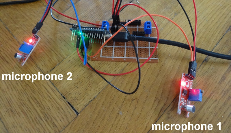
For the Arduino demonstration, cheap microphone boards take the place of your ears. A servo motor points to the direction of sound. This would be a good gimmick for a Halloween prop or a noise-sensitive security camera.

Math-wise, if you know the speed of sound, the distance between the sensors, and a few other pieces of data, you wind up with a fairly simple trigonometry problem. In non-math terms, it is easy to get a feel for why this works. If the sound hits both microphones at once, it must be coming from straight ahead. If it hits the left microphone first, it must be closer to that microphone and vice versa. If the sound were right in line with both microphones but closer to the left, the time delay would be exactly due to the speed of sound over the distance between the sensors. If the time is less than that, the sound must be somewhere in between.

The microphone modules have both analog outputs and digital outputs. The digital output triggers if the sound level exceeds a limit set by a potentiometer. By using these modules, the circuit is trivial. Just an Arudino, the two modules, and the servo motor.

Now imagine that you wanted all this spatial detail to come through your headphones. Recording binaural audio is a thing. You can 3D print a virtual head if you are interested. We’ve seen projects for this several times.

ATtiny Does 170×240 VGA With 8 Colors

The Arduino is a popular microcontroller platform for getting stuff done quickly: it’s widely available, there’s a wealth of online resources, and it’s a ready-to-use prototyping platform. On the opposite end of the spectrum, if you want to enjoy programming every bit of the microcontroller’s flash ROM, you can start with an arbitrarily tight resource constraint and see how far you can push it. [lucas]’s demo that can output VGA and stereo audio on an eight-pin DIP microcontroller is a little bit more amazing than just blinking an LED.

[lucas] is using an ATtiny85, the larger of the ATtiny series of microcontrollers. After connecting the required clock signal to the microcontroller to get the 25.175 Mhz signal required by VGA, he was left with only four pins to handle the four-colors and stereo audio. This is accomplished essentially by sending audio out at a time when the VGA monitor wouldn’t be expecting a signal (and [lucas] does a great job explaining this process on his project page). He programmed the video core in assembly which helps to optimize the program, and only used passive components aside from the clock and the microcontroller.

Be sure to check out the video after the break to see how a processor with only 512 bytes of RAM can output an image that would require over 40 KB. It’s a true testament to how far you can push these processors if you’re determined. We’ve also seen these chips do over-the-air NTSC, bluetooth, and even Ethernet.


Filed under: ATtiny Hacks

Old Kit Review – Silicon Chip Mini Stereo Amplifier

Introduction

In this review of an older kit we examine the aptly-named “Mini Stereo Amplifier” from Dick Smith Electronics (catalogue number K5008), based on the article published in the October 1992 issue of Silicon Chip magazine.

The purpose of the kit is to offer a stereo 1W+1W RMS amplifier for use with portable audio devices that only used headphones, such as the typical portable tape players or newly available portable CD players. I feel old just writing that. At the time it would have been quite a useful kit, paired with some inexpensive speakers the end user would have a neat and portable sound solution. So let’s get started.

Assembly

Larger kits like this one that couldn’t be retailed on hanger cards shipped in corrugated cardboard boxes that were glued shut. They looked good but as soon as a sneaky customer tore one open “to have a look” it was ruined and hard to sell:

The amplifier kit was from the time when DSE still cared about kits, so you received the sixteen page “Guide to Kit Construction” plus the kit instructions, nasty red disclaimer sheet, feedback card, plus all the required components and the obligatory coil of solder that was usually rubbish:

However the completeness of the kit is outstanding, everything is included for completion including an enclosure and handy front panel sticker:

… all the sockets, plenty of jumper wire and even the rubber feet:

The PCB is from the old-school of design – without any silk-screening or solder mask:

However the instructions are quite clear so you can figure out the component placement easily. Which brings us to that point – all the components went in with ease:

… then it was a matter of wiring in the sockets, volume potentiometer and power switch:

Instead of using a 3.5mm phono socket for power input, I used a 9V battery snap instead. The amplifier can run on voltages down to 1.8V so it will do for the limited use I have in mind for the amplifier. However in the excitement of assembly I forgot the power switch:

However it wasn’t any effort to rectify that. You will also notice three links on the PCB, which I fitted instead of making coils (more on this later). So at that point the soldering work is finished:

Now to drill out the holes on the faceplate. Instead of tapering out the slots on the side of the housing, I just drilled all the holes on the front panel:

Turns out the adhesive on the front panel sticker had lost its mojo, so I might head off and get some white-on-black tape for the label maker. However in the meanwhile we have one finished mini stereo amplifier, which reminds me of an old grade seven electronics project:

How it works

The amplifier is based on the STMicro TDA2822M (data sheet .pdf) dual low-voltage amplifier IC. In fact the circuit is a slight modification of the stereo example in the data sheet. As mentioned earlier, the benefit of this IC is that it can operate on voltates down to 1.8V, however to reach the maximum power output of 1W per channel into 8Ω loads you need a 9V supply. The output will drop to around 300 mW at 6V.

Finally the Silicon Chip design calls for a triplet of coils, one each on the stereo input wires – used to prevent the RF signal being “shunted away” from the amplifier inputs. The idea behind that was some portable radios used the headphones as an antenna, however we’ll use it with the audio out from a mobile phone so it was easier to skip hand-winding the coils and just put links in the PCB.

Using the Amplifier

The purpose of this kit was to have some sound while working in the garage, so I’ve fitted a pair of cheap 1W 8Ω speakers each to a length of wire and a 3.5mm plug as shown in the image above. And for that purpose, it works very well. In hindsight it turns out the speakers were rated at 1W peak not RMS, however they still sound great.

Conclusion

Another kit review over. This is a genuinely useful kit and a real shame you can’t buy one today. And again – to those who have been asking me privately, no I don’t have a secret line to some underground warehouse of old kits – just keep an eye out on ebay as they pop up now and again. Full-sized images and much more information about the kit are available on flickr.

And while you’re here – are you interested in Arduino? Check out my new book “Arduino Workshop” from No Starch Press.

In the meanwhile have fun and keep checking into tronixstuff.com. Why not follow things on twitterGoogle+, subscribe  for email updates or RSS using the links on the right-hand column? And join our friendly Google Group – dedicated to the projects and related items on this website. Sign up – it’s free, helpful to each other –  and we can all learn something.

The post Old Kit Review – Silicon Chip Mini Stereo Amplifier appeared first on tronixstuff.
Tronixstuff 21 Nov 23:33

**********Stereo Audio VU meter on Arduino**********

This blog is a sequel of “Tears of Rainbow”.  Using the same hardware set-up of Gigantic RGB LED display, I decided to re-work software a little bit, in order to display the true RMS amplitude of musical content. Video clip on youtube:                       VU_Meter   640×480                                      VU_Meter_HD

Objective:

  • Stereo input, process both channel;
  • Full audio band, 40 Hz – 20 kHz;
  • Fast update rate of visual output.
  • Precision Full-Wave  measurements. 

To process stereo input, this time arduino is switching ADC multiplexer every time when it finish sampling input data array (size=128). Two channels “interleaved” with frame rate 78 Hz, so during each frame only one channel sampled / processed, and update rate per channel is equals to 78 / 2 = 39 Hz, which is more than enough for most audio applications.

 I’m using FFT Radix-4  to extract RMS magnitude of audio waveform, and this is why:

1.  Sampling rate in this application is 10 kHz. How I achieved  20 kHz stated in objective section, doing sampling only 10 ksps?  >>>Aliasing!<<<   What is considered to be nightmare when we need spectral information from FFT output, aliasing in this project is really helpful, reflecting all spectral components around  axis – 10 kHz back “to the field”. As all bins going to be sum-up there is no issue, only benefits. Due aliasing, I’m able to use low sampling rate, and reduce CPU workload down to 52%.

2.  In order to get accurate magnitude calculation of RMS,  which is defined as square root of the sum of squares divided by number of samples per specified period of time:    V(rms) = √ ( ∑ Vi ^2 ) / N) DC offset  must be subtracted from the input raw data of each sample    Vi = Vac + Vdc   (if you remember, AtMega328 ADC needs DC offset to read AC negative half-wave).  The problem here, DC offset value is never known with high accuracy due bunch of reason, like voltage stability of PSU,  thermal effects, resistors tolerance (+/- 1 or 5 %), ADC internal non-linearity etc. Cure for this, which works quite well for monitoring electrical grid power, high pass filter (HPF). Only instead of single 50/60 Hz frequency of power line,  I have a wide frequency range, starting from 20 Hz and ending at 20 kHz. When I feed specification of the HPF:

  • Sample Rate (Hz) ? [0 to 20000]                     ? 10000
  • Desired stop-band attenuation (dB) [10 to 200] ? 40
  • Stop-band edge frequency Fa [0 to 5000]         ? 0
  • Pass-band edge frequency Fp [0 to 5000]        ? 40

to  Parks-McClellan FIR filter design algorithm (one of the most popular, and probably, the best) it provides the result:

  • …filter length: 551 …beta: 3.395321

551 coefficient to be multiplied and sum up (MAC-ed) every 100 usec! No way. I’m not sure, if it could be done on 32-bits 100 MHz platform with build-in MAC hardware, but there is no way for 8-bit 16 MHz Arduino.

IIR filter wouldn’t make much difference here. It has lower quantity of multiplications, but more sensitive for truncation and rounding error, so I’d have to use longer (32-bits?) variables, which is not desirable on 8-bit microprocessor at all.

And here comes FFT Radix-4, which easily fulfill this extra-tough requirements in the most efficient and elegant way. All I have to do, is just NOT include bin[0] in final sum, and all DONE!. TOP-FLAT  linear frequency response  40 Hz – 20 kHz  ( -3 dB ), with complete suppression of DC, and low frequency rumble below 20 Hz attenuation.  Linearity is better than +-1 dB between 80 – 9960 Hz.

Last things, audio front-end. As VU meter was designed in stereo version, I’ve build another “line-in”  pre-amplifier based on this kit: Super Ear Amplifier Kit

Link to Download a sketch:  Stereo_VU_Meter.


Modified Stereo VU meter, Logarithmic scale, 8 bars per channel, spacing 6 dB.

Dynamic range: 8 x 6 = 48 dB.  Stereo_VU_Meter(Log10).
 Next blog:   Extending dynamic range to 72 dB!